EP4563371A1 - Pneu de véhicule à deux roues pour roulage sur terrain accidenté - Google Patents
Pneu de véhicule à deux roues pour roulage sur terrain accidenté Download PDFInfo
- Publication number
- EP4563371A1 EP4563371A1 EP24214162.0A EP24214162A EP4563371A1 EP 4563371 A1 EP4563371 A1 EP 4563371A1 EP 24214162 A EP24214162 A EP 24214162A EP 4563371 A1 EP4563371 A1 EP 4563371A1
- Authority
- EP
- European Patent Office
- Prior art keywords
- blocks
- crown
- tire
- tread
- ground contacting
- Prior art date
- Legal status (The legal status is an assumption and is not a legal conclusion. Google has not performed a legal analysis and makes no representation as to the accuracy of the status listed.)
- Pending
Links
Images




Classifications
-
- B—PERFORMING OPERATIONS; TRANSPORTING
- B60—VEHICLES IN GENERAL
- B60C—VEHICLE TYRES; TYRE INFLATION; TYRE CHANGING; CONNECTING VALVES TO INFLATABLE ELASTIC BODIES IN GENERAL; DEVICES OR ARRANGEMENTS RELATED TO TYRES
- B60C11/00—Tyre tread bands; Tread patterns; Anti-skid inserts
- B60C11/03—Tread patterns
- B60C11/11—Tread patterns in which the raised area of the pattern consists only of isolated elements, e.g. blocks
-
- B—PERFORMING OPERATIONS; TRANSPORTING
- B60—VEHICLES IN GENERAL
- B60C—VEHICLE TYRES; TYRE INFLATION; TYRE CHANGING; CONNECTING VALVES TO INFLATABLE ELASTIC BODIES IN GENERAL; DEVICES OR ARRANGEMENTS RELATED TO TYRES
- B60C11/00—Tyre tread bands; Tread patterns; Anti-skid inserts
- B60C11/03—Tread patterns
- B60C11/0302—Tread patterns directional pattern, i.e. with main rolling direction
-
- B—PERFORMING OPERATIONS; TRANSPORTING
- B60—VEHICLES IN GENERAL
- B60C—VEHICLE TYRES; TYRE INFLATION; TYRE CHANGING; CONNECTING VALVES TO INFLATABLE ELASTIC BODIES IN GENERAL; DEVICES OR ARRANGEMENTS RELATED TO TYRES
- B60C11/00—Tyre tread bands; Tread patterns; Anti-skid inserts
- B60C11/03—Tread patterns
- B60C11/0306—Patterns comprising block rows or discontinuous ribs
-
- B—PERFORMING OPERATIONS; TRANSPORTING
- B60—VEHICLES IN GENERAL
- B60C—VEHICLE TYRES; TYRE INFLATION; TYRE CHANGING; CONNECTING VALVES TO INFLATABLE ELASTIC BODIES IN GENERAL; DEVICES OR ARRANGEMENTS RELATED TO TYRES
- B60C11/00—Tyre tread bands; Tread patterns; Anti-skid inserts
- B60C11/03—Tread patterns
- B60C11/032—Patterns comprising isolated recesses
-
- B—PERFORMING OPERATIONS; TRANSPORTING
- B60—VEHICLES IN GENERAL
- B60C—VEHICLE TYRES; TYRE INFLATION; TYRE CHANGING; CONNECTING VALVES TO INFLATABLE ELASTIC BODIES IN GENERAL; DEVICES OR ARRANGEMENTS RELATED TO TYRES
- B60C11/00—Tyre tread bands; Tread patterns; Anti-skid inserts
- B60C11/03—Tread patterns
- B60C11/12—Tread patterns characterised by the use of narrow slits or incisions, e.g. sipes
-
- B—PERFORMING OPERATIONS; TRANSPORTING
- B60—VEHICLES IN GENERAL
- B60C—VEHICLE TYRES; TYRE INFLATION; TYRE CHANGING; CONNECTING VALVES TO INFLATABLE ELASTIC BODIES IN GENERAL; DEVICES OR ARRANGEMENTS RELATED TO TYRES
- B60C11/00—Tyre tread bands; Tread patterns; Anti-skid inserts
- B60C11/03—Tread patterns
- B60C11/13—Tread patterns characterised by the groove cross-section, e.g. for buttressing or preventing stone-trapping
- B60C11/1369—Tie bars for linking block elements and bridging the groove
-
- B—PERFORMING OPERATIONS; TRANSPORTING
- B60—VEHICLES IN GENERAL
- B60C—VEHICLE TYRES; TYRE INFLATION; TYRE CHANGING; CONNECTING VALVES TO INFLATABLE ELASTIC BODIES IN GENERAL; DEVICES OR ARRANGEMENTS RELATED TO TYRES
- B60C11/00—Tyre tread bands; Tread patterns; Anti-skid inserts
- B60C11/03—Tread patterns
- B60C11/0311—Patterns comprising tread lugs arranged parallel or oblique to the axis of rotation
- B60C2011/0313—Patterns comprising tread lugs arranged parallel or oblique to the axis of rotation directional type
-
- B—PERFORMING OPERATIONS; TRANSPORTING
- B60—VEHICLES IN GENERAL
- B60C—VEHICLE TYRES; TYRE INFLATION; TYRE CHANGING; CONNECTING VALVES TO INFLATABLE ELASTIC BODIES IN GENERAL; DEVICES OR ARRANGEMENTS RELATED TO TYRES
- B60C2200/00—Tyres specially adapted for particular applications
- B60C2200/10—Tyres specially adapted for particular applications for motorcycles, scooters or the like
-
- B—PERFORMING OPERATIONS; TRANSPORTING
- B60—VEHICLES IN GENERAL
- B60C—VEHICLE TYRES; TYRE INFLATION; TYRE CHANGING; CONNECTING VALVES TO INFLATABLE ELASTIC BODIES IN GENERAL; DEVICES OR ARRANGEMENTS RELATED TO TYRES
- B60C2200/00—Tyres specially adapted for particular applications
- B60C2200/12—Tyres specially adapted for particular applications for bicycles
-
- B—PERFORMING OPERATIONS; TRANSPORTING
- B60—VEHICLES IN GENERAL
- B60C—VEHICLE TYRES; TYRE INFLATION; TYRE CHANGING; CONNECTING VALVES TO INFLATABLE ELASTIC BODIES IN GENERAL; DEVICES OR ARRANGEMENTS RELATED TO TYRES
- B60C2200/00—Tyres specially adapted for particular applications
- B60C2200/14—Tyres specially adapted for particular applications for off-road use
Definitions
- the present invention relates to a two-wheeled vehicle tire for running on rough terrain.
- Patent Document 1 Japanese unexamined patent application publication No. 2020-179744 has proposed a motorcycle tire for running on rough terrain which has a tread portion provided with a plurality of first blocks.
- Each of the first blocks includes a ground contacting surface, a pair of sipes extending to divide the ground contacting surface without intersecting each other, a first portion formed between the pair of sipes, and a pair of second portions formed on both outer sides of the pair of the sipes. Further, the first portion has a block height different from a block height of each of the second portions.
- the Patent Document 1 discloses a detailed embodiment in which middle blocks are configured as the first blocks described above.
- the blocks are configured to have ground contacting surfaces with narrow grooves or stepped surfaces, as in the tire described above, edge components of the blocks are increased, therefore, it is possible that traction performance and braking performance during straight running and during cornering are improved.
- edge components may differ significantly from block to block, which may result in deterioration of the transient characteristics of grip and response perceived by the driver during rolling (hereinafter referred to as "roll characteristics").
- the blocks near the tire equator are configured to have the stepped surfaces
- the tire outer diameter increases compared to the tire without the stepped surface, which necessitates adjusting the tire outer diameter to within specifications by a component other than the blocks.
- adjustments such as reducing the block height or decreasing the gauge of the tread rubber located radially inside the blocks, for example, may impair the shock-absorbing properties of the tire.
- the present invention was made in view of the above, and a primary object thereof is to provide a two-wheeled vehicle tire for running on rough terrain capable of exerting excellent roll characteristics while maintaining the shock-absorbing properties.
- the present invention is a two-wheeled vehicle tire for running on rough terrain having a tread portion, wherein the tread portion including:
- the two-wheeled vehicle tire for running on rough terrain exerts excellent rolling characteristics while maintaining the shock-absorbing properties by adopting the above configuration.
- FIG. 1 shows a lateral cross-sectional view of a tread portion 2 of a two-wheeled vehicle tire for running on rough terrain (hereinafter, may be simply referred to as "tire") 1 according to the present embodiment in a standard state.
- FIG. 2 is a planar development of the tread portion 2 of the tire 1.
- FIG. 1 corresponds to a cross-sectional view taken along A-A line of FIG. 2 .
- the term "standard state” refers to a state in which the tire is mounted on a standard rim, inflated to a standard inner pressure, and loaded with no tire load.
- the standard state means a standard use state according to the purpose of use of the tire and being loaded with no tire load.
- the dimensions and the like of various parts are the values measured in the standard state described above.
- standard rim refers to a wheel rim specified for the concerned tire by a standard included in a standardization system on which the tire is based, for example, the "normal wheel rim” in JATMA, "Design Rim” in TRA, and “Measuring Rim” in ETRTO.
- standard inner pressure refers to air pressure specified for the concerned tire by a standard included in a standardization system on which the tire is based, for example, the maximum air pressure in JATMA, the maximum value listed in the "TIRE LOAD LIMITS AT VARIOUS COLD INFLATION PRESSURES" table in TRA, and "INFLATION PRESSURE” in ETRTO.
- the tire 1 in the present embodiment is for motorcycles and is suitable as a tire for motocross competition, for example.
- the tire 1 of the present embodiment is suitably used as a rear wheel tire for motocross vehicles, for example.
- the present invention is not limited to such a manner.
- the tread portion 2 of the tire 1 in the present embodiment has an outer surface curved in an arc shape so as to be convex outward in the tire radial direction in a lateral cross section.
- the tire 1 in the present embodiment has a carcass and a tread reinforcement layer (not shown), for example.
- the tread portion 2 includes a plurality of blocks 5 raised from a tread bottom surface 4.
- the blocks 5 sticks into the road surface and exerts high reaction force. Therefore, the tread bottom surface 4 can also contact the road surface.
- the tread portion 2 of the tire 1 of the present invention has a directional pattern bound with an intended tire rotational direction (R).
- the tire rotational direction (R) is indicated by letters or symbols on the sidewall portion 3 (shown in FIG. 1 ), for example.
- the present invention is not limited to such a manner.
- the tread portion 2 includes a first tread edge T1, a second tread edge T2, a tread development width (TWe) from the first tread edge T1 to the second tread edge T2, and the tire equator (C).
- the first tread edge T1 and the second tread edge T2 each mean the axially outer edges of the ground contacting surfaces of the blocks 5 included in the axially outermost block row among the blocks 5 arranged in the tread portion 2 in a respective axial half of the tire.
- the tread development width (TWe) corresponds to the distance in the tire axial direction from the first tread edge T1 to the second tread edge T2 when the tread portion 2 is developed on a plane.
- the tire equator (C) is a virtual line extending parallel to the tire circumferential direction on the axial center position of the tread portion.
- Tread portion 2 includes a crown region 6 and side regions 7.
- the crown region 6 has a width (Wc) of 20% of the tread development width (TWe) centered on the tire equator (C).
- the side regions 7 are the regions located on both axially outer sides, one on each side, of the crown region 6. That is, the two side regions 7 are arranged so as to sandwich the crown region 6.
- boundaries 8 between the crown region 6 and the side regions 7 are indicated by a double-dashed line.
- the tread portion 2 includes a plurality of crown blocks 10 provided in the crown region 6 and a plurality of outer blocks 20 provided in the side regions 7.
- the blocks 5 having the ground contacting surfaces with the boundaries 8 between the crown region 6 and the side regions 7 passing through correspond to the crown blocks 10.
- each of the outer blocks 20 has the entire ground contacting surface located axially outside a respective one of the boundaries 8.
- the ground contacting surface of the block means the area of the outer surface of the block that extends along the virtual tread bottom surface 4 passing through the root of the block, and more specifically, the area where the angle with respect to the tread bottom surface 4 is 30 degrees or less.
- the outer blocks 20 include a plurality of shoulder blocks 40 including the first tread edge T1 or the second tread edge T2 and a plurality of middle blocks 30 arranged between the shoulder blocks 40 and the crown region 6 in each axial half of the tread portion 2.
- FIG. 3 is an end view taken along B-B line of FIG. 2 , showing a cross-sectional view of one of the shoulder blocks 40.
- FIG. 4 is an end view taken along C-C line of FIG. 2 , showing a cross-sectional view of one of the middle blocks 30.
- each of the outer blocks 20 is provided with a narrow groove 15 or configured as a stepped surface 25 including a base surface 26 and a protruding surface 27 that protrudes locally outward in the block height direction relative to the base surface 26. It should be noted that the entire protruding surface 27 protrudes outward in the block height direction relative to the base surface 26 in the present embodiment.
- the above-mentioned narrow groove 15 means a groove having a width of 3.0 mm or less, which includes a minute incision known as so called a sipe.
- FIG. 7 shows an end view taken along D-D line of FIG. 2 as a cross-sectional view of the crown blocks 10.
- the ground contacting surface of each of the crown blocks 10 is a non-step surface 28 having the narrow groove 15 and without having the protruding surface 27 (shown in FIG. 3 and FIG. 4 ).
- the non-step surface 28 means the surface having two surface portions divided by the narrow groove 15 without forming a step since the height of one surface portion is substantially the same as the height of the other surface portion.
- surfaces that include steps of 0.5 mm or less shall be treated as non-step surfaces.
- the tire of the present invention can exert excellent roll characteristics while maintaining the shock-absorbing properties.
- the reasons for this are as follows.
- the ground contacting surface of each of the outer blocks 20 is formed with the narrow grooves 15 or formed as a stepped surface 25.
- the ground contacting surface of each of the crown blocks 10 has the narrow groove 15 formed therein and is the non-step surface 28 which does not have the protruding surface.
- the edge components of all the blocks 5 are increased by the narrow grooves 15 or the stepped surface 25, and therefore improvement in the roll characteristics can be expected.
- the tire outer diameter increases compared to the case without the stepped surface. This may result in the need to adjust the tire outer diameter to fit within the standard by reducing the block height or by reducing the gauge of the tread rubber located radially inside the blocks, and these adjustments may impair the shock-absorbing properties of the tire.
- the ground contacting surfaces of the crown blocks 10 are the non-step surfaces 28, therefore, the tire outer diameter is not increased unnecessarily, thereby, it is possible that the shock-absorbing properties are maintained.
- the outer blocks 20 arranged on the first tread edge T1 side of the tire equator (C) are shown as examples, but these configurations can also be applied to the outer blocks 20 arranged on the second tread edge T2 side of the tire equator (C).
- the number N1 of the outer blocks 20 having the protruding surfaces 27 is 75% or less of the total number Nt of the crown blocks 10 and the outer blocks 20.
- the number N1 is from 60% to 70% of the total number Nt in the present embodiment. Such an arrangement of the blocks can further improve the roll characteristics.
- the number N2 of the blocks 5 having the narrow grooves 15 is in the range from 40% to 200% of the number N1, and preferably in the range from 130% to 170%. Such an arrangement of the blocks 5 can improve the roll characteristics while maintaining anti-wear performance of the tread portion 2.
- the tread portion 2 in the present embodiment has tie bars 35 each connecting a respective pair of the blocks 5 adjacent to each other.
- FIG. 8 shows an end view taken along E-E line of FIG. 2 as an example of the tie bar 35.
- the tie bars 35 are locally raised from the tread bottom surface 4, and can increase the rigidity of the base portions of the blocks.
- a raised height (h1) of each of the tie bars 35 is less than 20% of the height of the adjacent blocks, and specifically, from 1.0 to 2.5 mm.
- the dimensions of the tie bars 35 that connect the crown blocks 10 are different from those described above and will be described later.
- each of the crown blocks 10 is connected, directly or indirectly, to a respective one of the crown blocks 10 adjacent thereto and adjacent ones of the outer blocks 20 by the tie bars 35.
- Each of the outer blocks 20 is connected to the outer blocks 20 adjacent thereto or adjacent ones of the crown blocks 10 by one or more tie bars 35.
- FIG. 9 shows the shoulder blocks 40.
- the ground contacting surface of each of the shoulder blocks 40 in the present embodiment is provided with the narrow groove 15 extending in the tire circumferential direction. This narrow groove 15 completely crosses the ground contacting surface (40s) of each of the shoulder blocks 40 in the tire circumferential direction to divide the ground contacting surface (40s) into the base surface 26 located on the first tread edge T1 side and the protruding surface 27 located on the tire equator (C) side.
- the narrow groove 15 is inclined to the tire equator (C) side as it goes toward the heel side (leading side; first side in the tire circumferential direction) in the tire rotational direction (R), for example.
- the narrow groove 15 has an angle 01 the with respect to the tire circumferential direction of 45 degrees or less, for example, and preferably in the range from 5 to 15 degrees.
- the angle ⁇ 1 refers to the average angle of the narrow groove 15 with respect to the tire circumferential direction.
- the average angle corresponds to an angle obtained by dividing the narrow groove 15 into a plurality of minute regions and dividing the sum of the angles of the minute regions relative to the tire circumferential direction by the number of the minute regions.
- the angles of various parts shall be measured in the same manner.
- the narrow groove 15 has a groove width increasing continuously, over the entire length of the narrow groove in the present embodiment, toward the heel side in the tire rotational direction (R).
- the narrow groove 15 has a maximum groove width at its end on the heel side, and a minimum groove width at its end on the toe side (trailing side; second side in the tire circumferential direction) in the tire rotational direction (R).
- the minimum groove width is in the range from 65% to 80% of the maximum groove width, for example.
- the narrow grooves 15 configured as such can provide a large reaction force during braking, therefore, it is possible that the braking performance is improved.
- each of the shoulder blocks 40 in the present embodiment has the narrow groove 15 formed therein and the ground contacting surface (40s) is configured as the stepped surfaces 25. Further, this stepped surface 25 has the base surface 26 disposed on the first tread edge T1 side and the protruding surface 27 disposed on the tire equator (C) side. An amount of step difference (t1) between the base surface 26 and the protruding surface 27 is in the range from 1.0 to 2.0 mm, for example.
- the shoulder blocks 40 configured as such help improve cornering performance.
- the area of the base surface 26 is from 55% to 65% of the total area of the ground contacting surface (40s) in each of the shoulder blocks 40.
- the total area of the ground contacting surface is the sum of the area of the base surface 26 and the area of the protruding surface 27, and the same applies hereafter.
- the area of the protruding surface 27 is from 35% to 45% of the total area of the ground contacting surface (40s) in each of the shoulder blocks 40. This allows the shoulder blocks 40 to easily dig into the road surface while maintaining the durability of the shoulder blocks 40.
- the shoulder blocks 40 include first shoulder blocks 41 and second shoulder blocks 42 with different shapes of the ground contacting surface.
- the ground contacting surface of each of the first shoulder blocks 41 has two edges (41a) extending in the tire axial direction and inclined to the same side with respect to the tire axial direction. Specifically, the two edges (41a) of each of the first shoulder blocks 41 are inclined to the toe side in the tire rotational direction (R) as it goes from the first tread edge T1 toward the tire equator (C).
- the first shoulder blocks 41 configured as such can exert excellent traction performance during cornering.
- each of the second shoulder blocks 42 has two edges (42a) extending in the tire axial direction and inclined to opposite sides to each other with respect to the tire axial direction. In a preferred embodiment, these two edges (42a) are inclined so as to approach each other toward the tire equator (C). As a result, the ground contacting surface of each of the second shoulder blocks 42 has a circumferential length that continuously decreases toward the tire equator (C).
- the second shoulder blocks 42 configured as such have a relatively high rigidity on the first tread edge T1 side, which helps to improve the roll characteristics.
- each of the first shoulder blocks 41 is connected to one of the second shoulder blocks 42 adjacent thereto by a respective one of the tie bars 35.
- these shoulder blocks 40 are also connected to a respective one of second middle blocks 32 described below by a respective one of the tie bars 35. This makes it difficult for the shoulder blocks 40 to collapse, therefore, the traction performance and the braking performance are improved. It should be noted that the tie bars 35 are omitted in FIG. 9 .
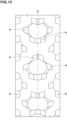
- FIG. 10 shows an enlarged view of a plurality of the middle blocks 30.
- each of the middle blocks 30 in the present embodiment has a ground contacting surface (30s) provided with the narrow groove 15.
- the ground contacting surface (30s) has outer peripheral edges including a pair of axial edges extending in the tire axial direction and a pair of circumferential edges extending in the tire circumferential direction.
- the narrow groove 15 extends in a curved or bent manner so as to connect one of the axial edges with one of the circumferential edges. As a result, the narrow groove 15 divides the ground contacting surface (30s) of each of the middle blocks 30 into the base surface 26 and the protruding surface 27.
- the narrow groove 15 extends from a toe side edge (30a) extending in the tire axial direction on the toe side in the tire rotational direction (R) to a tire equator side edge (30c) extending in the tire circumferential direction on the tire equator (C) side among the outer peripheral edges of the ground contacting surface (30s), for example.
- the narrow groove 15 of each of the middle blocks 30 includes a first groove portion 16, a second groove portion 17, and a third groove portion 18.
- the first groove portion 16 extends in the tire circumferential direction from the toe side edge (30a).
- the second groove portion 17 is continuous with the first groove portion 16 and extends at an angle with respect to the tire axial direction.
- the third groove portion 18 extends in the tire axial direction from the second groove portion 17 to the tire equator side edge (30c).
- An angle ⁇ 2 between the first groove portion 16 and the third groove portion 18 is in the range from 70 to 110 degrees, and preferably from 80 to 90 degrees, for example.
- the narrow grooves 15 configured as such provide friction in multiple directions, thereby, it is possible that the roll characteristics and the traction performance are improved in a good balance.
- the angle ⁇ 2 corresponds to the sum of the average angle of the first groove portion 16 with respect to an arbitrary reference line and the average angle of the third groove portion 18 with respect to the reference line, for example.
- the arbitrary reference line is an imaginary straight line inclined at 45 degrees with respect to the tire circumferential direction, for example.
- the method for measuring the average angle is as described above. Furthermore, the angle between two members described below can also be determined in a similar manner.
- the first groove portion 16 of the narrow groove 15 has a constant groove width along a longitudinal direction thereof in each of the middle blocks 30. Further, it is preferred that the groove width of the narrow groove 15 increases continuously from the first groove portion 16 side end of the second groove portion 17 to the tire equator side edge (30c) side end of the third groove portion 18 in each of the middle blocks 30.
- the narrow grooves 15 has a maximum groove width at the end thereof communicating with the tire equator side edge (30c), and the narrow groove 15 has a minimum groove width at the first groove portion 16 thereof in each of the middle blocks 30. Further, the minimum groove width is in the range from 20% to 40% of the maximum groove width in the narrow groove 15 of each of the middle blocks 30, for example.
- the narrow grooves 15 configured as such can further improve the roll characteristics.
- each of the middle blocks 30 in the present embodiment has the narrow groove 15 formed therein and the ground contacting surface (30s) configured as the stepped surface 25.
- Each of the middle blocks 30 has an amount of step difference (t2) between the base surface 26 and the protruding surface 27 in the range from 1.0 to 2.0 mm, for example.
- the protruding surface 27 included in the stepped surface 25 of each of the middle blocks 30 is a surface surrounded by the narrow groove 15, a part of the toe side edge (30a), and a part of the tire equator side edge (30c). Furthermore, the base surface 26 included in the stepped surface 25 of each of the middle blocks 30 is disposed so as to surround a part of the protruding surface 27.
- the base surface 26 is a surface surrounded by the narrow groove 15, the remainder of the toe side edge (30a), the remainder of the tire equator side edge (30c), a heel side edge (30b) extending in the tire axial direction on the heel side in the tire rotational direction (R), and a tread edge side edge (30d) extending in the tire circumferential direction on the respective tread edge side (the first tread edge T1 side in this case).
- the protruding surface 27 has a smaller area than an area of the base surface 26 in the ground contacting surface (30s) of each of the middle blocks 30.
- the middle blocks 30 configured as such easily stick into uneven road surfaces and thus can exert a large reaction force.
- the area of the base surface 26 is in the range from 70% to 85% of a total area of the ground contacting surface (30s) in each of the middle blocks 30. Further, the area of the protruding surface 27 is in the range from 15% to 30% of the total area of the ground contacting surface (30s) in each of the middle blocks 30. Thereby, it is possible that the roll characteristics are improved while the durability of the middle blocks 30 is maintained.
- the heel side edge (30b) and the toe side edge (30a) are inclined to the same side with respect to the tire axial direction in each of the middle blocks 30. These edges have an angle ⁇ 3 in the range from 5 to 30 degrees with respect to the tire axial direction, for example.
- the middle blocks 30 in the present embodiment include blocks with these edges inclined to one side and blocks with these edges inclined to the other side with respect to the tire axial direction.
- the middle blocks 30 there are two types of the middle blocks 30 with regard to the edge inclination, and they are the middle blocks 30 with the heel side edge (30b) and the toe side edge (30a) inclined to the toe side in the tire rotational direction (R) as they go toward the first tread edge T1 and the middle blocks 30 with these edges inclined to heel side in the tire rotational direction (R) as they go toward the first tread edge T1.
- These two types of the middle blocks 30 are arranged in the tire circumferential direction in a mixed manner. Such an arrangement of the middle blocks 30 can provide stable reaction force on a variety of road surface conditions and thus can further improve the roll characteristics.
- the middle blocks 30 include first middle blocks 31 and the second middle blocks 32 arranged alternately, one by one in each axial half of the tread portion 2 in the present embodiment, in the tire circumferential direction, for example.
- the first middle blocks 31 are connected to the crown blocks 10 by the tie bars 35.
- the second middle blocks 32 are connected to the shoulder blocks 40 by the tie bars 35.
- the tie bars 35 connecting the first middle blocks 31 and the crown blocks 10 have the same raised height (h1) (shown in FIG. 8 ) as the aforementioned tie bars 35. Due to the arrangement of the tie bars 35 described above, the first middle blocks 31 and the second middle blocks 32 have different directions in which the blocks tend to collapse (or lean or fall).
- one first middle block 31 is connected by two tie bars 35 with two crown blocks 10 that are one crown block 10 adjacent on one side in the tire circumferential direction and another crown block 10 on the other side in the tire circumferential direction.
- the tie bars 35 connecting the first middle blocks 31 and the crown blocks 10 include those in which the widths increase continuously from the crown blocks 10 to the first middle blocks 31, those in which the widths decrease continuously from the crown blocks 10 to the first middle blocks 31, and those in which the widths are constant.
- these three types of the tie bars 35 are arranged in the tire circumferential direction in a mixed manner.
- the second middle blocks 32 are connected with both the first shoulder blocks 41 and the second shoulder blocks 42. Specifically, one second middle block 32, one first shoulder block 41 and one second shoulder block 42 are connected by one tie bar 35 which is formed by the entirely raised area surrounded by these blocks. This arrangement of the blocks and the tie bars provides excellent roll characteristics and excellent cornering performance.
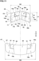
- FIG. 11 shows an enlarged view of a plurality of the crown blocks 10. It should be noted that the tie bars 35 (shown in FIG. 2 ) connecting the first middle blocks 31 and the crown blocks 10 are omitted in FIG. 11 . As shown in FIG. 11 , in each of the crown blocks 10, the narrow groove 15 provided in a ground contacting surface (10s) has both ends communicating with the outer peripheral edges of the ground contacting surface (10s).
- each of the crown blocks 10 the narrow groove 15 extends from a toe side edge (10a) to a tire equator side edge (10c), for example.
- the toe side edge (10a) is an edge extending in the tire axial direction on the toe side in the tire rotational direction (R)
- the tire equator side edge (10c) is an edge extending in the tire circumferential direction on the tire equator (C) side.
- each of the narrow grooves 15 of the crown blocks 10 includes a circumferential portion 23 extending in the tire circumferential direction and an axial portion 24 extending in the tire axial direction.
- the circumferential portion 23 extends in the tire circumferential direction from the toe side edge (10a).
- the axial portion 24 extends from the circumferential portion 23 to the tire equator side edge (10c).
- An angle ⁇ 4 between the circumferential portion 23 and the axial portion 24 is in the range from 70 to 90 degrees, for example.
- the narrow grooves 15 configured as such of the crown blocks 10 provide friction in multiple directions and thus can exert excellent roll characteristics and excellent traction performance.
- the narrow groove 15 extends with a constant groove width from the toe side edge (10a) side end to the tire equator side edge (10c) side end, in a preferred embodiment.
- the average groove width of the narrow grooves 15 provided in the crown blocks 10 is smaller than the average groove width of the narrow grooves 15 provided in the outer blocks 20. Therefore, the roll characteristics are further improved.
- the average groove width corresponds to the opening area of the narrow groove 15 divided by the length of the narrow groove 15 (so-called periphery length) for each of the narrow grooves 15.
- Each of the ground contacting surfaces (10s) of the crown blocks 10 includes a first surface 36 and a second surface 37 separated by the narrow groove 15.
- the first surface 36 is surrounded by the narrow groove 15, a portion of the toe side edge (10a), and a portion of the tire equator side edge (10c).
- the second surface 37 is disposed so as to partially surround the first surface 36. As a result, the second surface 37 is surrounded by the narrow groove 15, the remainder of the toe side edge (10a), the remainder of the tire equator side edge (10c), a heel side edge (10b), and a tread edge side edge (10d).
- the heel side edge (10b) is an edge of the ground contacting surface (10s) extending in the tire axial direction on the heel side in the tire rotational direction (R), and the tread edge side edge (10d) is an edge of the ground contacting surface (10s) extending in the tire circumferential direction on the first tread edge T1 side or the second tread edge T2 side (shown in FIG. 2 ).
- the second surface 37 has a larger area than the first surface 36 in each of the crown blocks 10.
- the area of the first surface 36 is in the range from 10% to 30% of the total area of the ground contacting surface (10s) of the crown block 10 (the sum of the area of the first surface 36 and the area of the second surface 37).
- the area of the second surface 37 is in the range from 70% to 90% of the total area of the ground contacting surface (10s) for each of the crown blocks 10. Therefore, it is possible that the traction performance and the braking performance are improved while the durability of the crown blocks 10 are maintained.
- a distance L2 in the tire circumferential direction from a centroid (38c) of a virtual ground contacting surface 38 consisting of the first surface 36, the narrow groove 15, and the second surface 37 to a centroid (36c) of the first surface 36 is preferably 20% or more, more preferably from 30% to 40%, of a length L1 in the tire circumferential direction of the virtual ground contacting surface 38 on the centroid (38c) of the virtual ground contacting surface 38. Therefore, the amount of deformation in the area including the first surface 36 is increased, thereby, it is possible that the traction performance and the braking performance are further improved.
- the sum of the areas of the first surfaces 36 of the crown blocks 10 and the areas of the protruding surfaces 27 of the outer blocks 20 is preferably in the range from 20% to 60% of the sum of the areas of the ground contacting surfaces of the blocks 5.
- the heel side edge (10b) and the toe side edge (10a) are inclined to the same side with respect to the tire axial direction in each of the crown blocks 10. These edges have an angle ⁇ 5 in the range from 10 to 20 degrees with respect to the tire axial direction, for example.
- there are two types of the crown blocks 10 with these edges inclined to opposite sides that is, the first-type crown blocks 10 with the heel side edges (10b) and the toe side edges (10a) inclined to the toe side in the tire rotational direction (R) as they go toward the tire equator (C), and the second-type crown blocks 10 with these edges inclined to the heel side in the tire rotational direction (R) as they go toward the tire equator (C).
- These two types of the crown blocks 10 are arranged in the tire circumferential direction in a mixed manner. As a result, the crown blocks 10 generate frictional force in multiple directions, therefore, the traction performance is further improved.
- an angle ⁇ 6 between the heel side edge (10b) and the axial portion 24 is 20 degrees or less, more preferably from 5 to 15 degrees, for example. Thereby, these edges work together to provide greater frictional force, therefore, the traction performance and the braking performance are improved.
- the crown blocks 10 include first crown blocks 11 and second crown blocks 12.
- Each of the first crown blocks 11 is connected by a respective one of the tie bars 35 with one of the first middle blocks 31 adjacent on the heel side in the tire rotational direction (R).
- Each of the second crown blocks 12 is connected by a respective one of the tie bars 35 with one of the first middle blocks 31 adjacent on the toe side in the tire rotational direction (R).
- the crown blocks 10 in the present embodiment consist of the first crown blocks 11 and the second crown blocks 12.
- first crown blocks 11 arranged so as to sandwich the tire equator (C) are connected by one of the tie bars 35 to form one first crown block pair 46.
- second crown blocks 12 arranged so as to sandwich the tire equator (C) are connected by one of the tie bars 35 to form one second crown block pair 47.
- the first crown block pairs 46 and the second crown block pairs 47 are arranged alternately, one by one in the present embodiment, in the tire circumferential direction. Thereby, excellent traction performance and excellent braking performance can be obtained under various road surface conditions.
- one first crown block pair 46 and one second crown block pair 47 are connected with a common one of the first middle blocks 31 by the tie bars 35 in the present embodiment.
- multiple virtual annular bodies 45 are arranged in the tire circumferential direction.
- Each of the virtual annular bodies 45 is formed by one first crown block pair 46, one second crown block pair 47, and two first middle blocks 31 connected by the tie bars 35 so as to have a ring shape in a tread plan view.
- the second crown block pair 47 is located on the heel side in the tire rotational direction (R) relative to the first crown block pair 46 in each of the virtual annular bodies 45.
- each of the tie bars 35 that connects two crown blocks 10 adjacent to each other in the tire axial direction has a raised height (h2) greater than that of the tie bar 35 shown in FIG.8 .
- the raised height (h2) of this type of the tie bars 35 is in the range from 20% to 50% of a height (h3) of the crown blocks 10, for example.
- the maximum width W2 (measured on the ground contacting surface, and the same applies hereinafter) in the tire axial direction of each of the second crown block pairs 47 is larger than the maximum width W1 in the tire axial direction of each of the first crown block pairs 46.
- the maximum width W2 of each of the second crown block pairs 47 is in the range from 130% to 160% of the maximum width W1 of each of the first crown block pairs 46.
- each of the tie bars 35 included in the second crown block pairs 47 has an axial width larger than an axial width of each of the tie bars 35 included in the first crown block pairs 46. Therefore, the virtual annular bodies 45 can grip more mud during running on muddy road surfaces, thereby, the traction performance and the braking performance are further improved.
- FIG. 12 is a development view of the tread portion 2 according to yet another embodiment of the present invention.
- the outer blocks 20 in this embodiment have ground contacting surfaces (20s) that are not provided with the narrow grooves.
- the ground contacting surfaces (20s) of the outer blocks 20 in this embodiment are configured as the stepped surfaces 25, and a boundary 34 between the base surface 26 and the protruding surface 27 in each of the ground contacting surfaces (20s) is shown by a solid line.
- the protruding surfaces 27 can provide sufficient edge components and can exert excellent roll characteristics.
- the gauge of the tread rubber (not shown) is slightly reduced on the radially inner side of the crown blocks (b) in order to adjust the tire outer diameter to stay within the standard.
- the tires in the References 1 and 2 are substantially the same as the tires in the Examples, except for the above points. These test tires were tested for the roll characteristics, the shock-absorbing properties, the traction performance, and the braking performance. The common specifications of the test tires and the test methods were as follows:
- a two-wheeled vehicle tire for running on rough terrain having a tread portion, wherein the tread portion including:
Landscapes
- Engineering & Computer Science (AREA)
- Mechanical Engineering (AREA)
- Tires In General (AREA)
Applications Claiming Priority (1)
| Application Number | Priority Date | Filing Date | Title |
|---|---|---|---|
| JP2023202793A JP2025088226A (ja) | 2023-11-30 | 2023-11-30 | 不整地走行用の二輪車用タイヤ |
Publications (1)
| Publication Number | Publication Date |
|---|---|
| EP4563371A1 true EP4563371A1 (fr) | 2025-06-04 |
Family
ID=93607897
Family Applications (1)
| Application Number | Title | Priority Date | Filing Date |
|---|---|---|---|
| EP24214162.0A Pending EP4563371A1 (fr) | 2023-11-30 | 2024-11-20 | Pneu de véhicule à deux roues pour roulage sur terrain accidenté |
Country Status (4)
| Country | Link |
|---|---|
| US (1) | US20250178379A1 (fr) |
| EP (1) | EP4563371A1 (fr) |
| JP (1) | JP2025088226A (fr) |
| CN (1) | CN120056654A (fr) |
Families Citing this family (1)
| Publication number | Priority date | Publication date | Assignee | Title |
|---|---|---|---|---|
| US12600425B2 (en) * | 2024-05-15 | 2026-04-14 | Shimano Inc. | Detection system, detection method, and computer-readable storage medium |
Citations (6)
| Publication number | Priority date | Publication date | Assignee | Title |
|---|---|---|---|---|
| EP3056357B1 (fr) * | 2013-10-28 | 2018-01-10 | Sumitomo Rubber Industries, Ltd. | Pneu pour motocycle convenant à un déplacement sur un sol irrégulier |
| EP3501854B1 (fr) * | 2017-12-19 | 2020-05-27 | Sumitomo Rubber Industries, Ltd. | Pneumatique de motocyclette pour conduite sur terrain accidenté |
| JP2020179744A (ja) | 2019-04-24 | 2020-11-05 | 住友ゴム工業株式会社 | タイヤ |
| EP3677442B1 (fr) * | 2018-12-28 | 2021-04-07 | Sumitomo Rubber Industries, Ltd. | Pneu hors route |
| JP2022020427A (ja) * | 2020-07-20 | 2022-02-01 | 住友ゴム工業株式会社 | 不整地走行用の二輪車用タイヤ |
| EP3795383B1 (fr) * | 2018-05-15 | 2023-06-28 | Bridgestone Corporation | Pneu de bicyclette |
Family Cites Families (7)
| Publication number | Priority date | Publication date | Assignee | Title |
|---|---|---|---|---|
| JPS5920706A (ja) * | 1982-07-27 | 1984-02-02 | Sumitomo Rubber Ind Ltd | 荒地走行車輛用タイヤ |
| JP5337199B2 (ja) * | 2011-05-30 | 2013-11-06 | 住友ゴム工業株式会社 | 不整地走行用の自動二輪車用タイヤ |
| JP5616924B2 (ja) * | 2012-04-27 | 2014-10-29 | 住友ゴム工業株式会社 | 不整地走行用の空気入りタイヤ |
| JP6915524B2 (ja) * | 2017-12-19 | 2021-08-04 | 住友ゴム工業株式会社 | 不整地用の自動二輪車用タイヤ |
| USD978067S1 (en) * | 2020-03-19 | 2023-02-14 | Sumitomo Rubber Industries, Ltd. | Tire for motorcycle |
| JP7505249B2 (ja) * | 2020-05-11 | 2024-06-25 | 住友ゴム工業株式会社 | 不整地走行用モーターサイクルタイヤ |
| CN215621205U (zh) * | 2021-02-03 | 2022-01-25 | 建大橡胶(中国)有限公司 | 一种轻量化越野摩托车轮胎 |
-
2023
- 2023-11-30 JP JP2023202793A patent/JP2025088226A/ja active Pending
-
2024
- 2024-09-30 US US18/901,911 patent/US20250178379A1/en active Pending
- 2024-11-05 CN CN202411566399.XA patent/CN120056654A/zh active Pending
- 2024-11-20 EP EP24214162.0A patent/EP4563371A1/fr active Pending
Patent Citations (6)
| Publication number | Priority date | Publication date | Assignee | Title |
|---|---|---|---|---|
| EP3056357B1 (fr) * | 2013-10-28 | 2018-01-10 | Sumitomo Rubber Industries, Ltd. | Pneu pour motocycle convenant à un déplacement sur un sol irrégulier |
| EP3501854B1 (fr) * | 2017-12-19 | 2020-05-27 | Sumitomo Rubber Industries, Ltd. | Pneumatique de motocyclette pour conduite sur terrain accidenté |
| EP3795383B1 (fr) * | 2018-05-15 | 2023-06-28 | Bridgestone Corporation | Pneu de bicyclette |
| EP3677442B1 (fr) * | 2018-12-28 | 2021-04-07 | Sumitomo Rubber Industries, Ltd. | Pneu hors route |
| JP2020179744A (ja) | 2019-04-24 | 2020-11-05 | 住友ゴム工業株式会社 | タイヤ |
| JP2022020427A (ja) * | 2020-07-20 | 2022-02-01 | 住友ゴム工業株式会社 | 不整地走行用の二輪車用タイヤ |
Also Published As
| Publication number | Publication date |
|---|---|
| CN120056654A (zh) | 2025-05-30 |
| US20250178379A1 (en) | 2025-06-05 |
| JP2025088226A (ja) | 2025-06-11 |
Similar Documents
| Publication | Publication Date | Title |
|---|---|---|
| EP1992504B1 (fr) | Pneu de motocyclette pour déplacements hors-route | |
| EP3118022B1 (fr) | Pneumatique | |
| US20210170799A1 (en) | Tire for running on rough terrain | |
| EP3647078B1 (fr) | Pneumatique | |
| EP3603992B1 (fr) | Pneu pour terrain accidenté | |
| EP3885164B1 (fr) | Pneu de motocyclette pour terrains accidentés | |
| EP4563371A1 (fr) | Pneu de véhicule à deux roues pour roulage sur terrain accidenté | |
| EP3521068B1 (fr) | Pneu de véhicule à deux roues | |
| US11325425B2 (en) | Tyre for a motorcycle for rough terrain | |
| EP3611037B1 (fr) | Pneu pour terrain accidenté | |
| EP3616945B1 (fr) | Pneumatique de motocyclette pour tout-terrain | |
| EP3597451B1 (fr) | Pneumatique | |
| EP3524442B1 (fr) | Pneu de véhicule à deux roues | |
| EP4091843B1 (fr) | Pneu pour terrain accidenté | |
| EP3318419B1 (fr) | Pneumatique et véhicule à trois roues le comprenant | |
| EP3885165B1 (fr) | Pneu de motocyclette pour terrains accidentés | |
| EP3666552B1 (fr) | Pneumatique | |
| EP3904122B1 (fr) | Pneumatique | |
| US12370840B2 (en) | Two-wheel vehicle tire | |
| JP7655064B2 (ja) | 自動二輪車用タイヤ |
Legal Events
| Date | Code | Title | Description |
|---|---|---|---|
| PUAI | Public reference made under article 153(3) epc to a published international application that has entered the european phase |
Free format text: ORIGINAL CODE: 0009012 |
|
| STAA | Information on the status of an ep patent application or granted ep patent |
Free format text: STATUS: THE APPLICATION HAS BEEN PUBLISHED |
|
| AK | Designated contracting states |
Kind code of ref document: A1 Designated state(s): AL AT BE BG CH CY CZ DE DK EE ES FI FR GB GR HR HU IE IS IT LI LT LU LV MC ME MK MT NL NO PL PT RO RS SE SI SK SM TR |
|
| STAA | Information on the status of an ep patent application or granted ep patent |
Free format text: STATUS: REQUEST FOR EXAMINATION WAS MADE |
|
| 17P | Request for examination filed |
Effective date: 20250730 |
|
| P01 | Opt-out of the competence of the unified patent court (upc) registered |
Free format text: CASE NUMBER: UPC_APP_0005161_4563371/2026 Effective date: 20260212 |