EP4563387A1 - Strategien zur handhabung der systemdynamik in einer batterielosen niederspannungsarchitektur eines elektrofahrzeugs - Google Patents
Strategien zur handhabung der systemdynamik in einer batterielosen niederspannungsarchitektur eines elektrofahrzeugs Download PDFInfo
- Publication number
- EP4563387A1 EP4563387A1 EP23213044.3A EP23213044A EP4563387A1 EP 4563387 A1 EP4563387 A1 EP 4563387A1 EP 23213044 A EP23213044 A EP 23213044A EP 4563387 A1 EP4563387 A1 EP 4563387A1
- Authority
- EP
- European Patent Office
- Prior art keywords
- circuit
- switch
- indication
- voltage
- threshold
- Prior art date
- Legal status (The legal status is an assumption and is not a legal conclusion. Google has not performed a legal analysis and makes no representation as to the accuracy of the status listed.)
- Pending
Links
Images


Classifications
-
- B—PERFORMING OPERATIONS; TRANSPORTING
- B60—VEHICLES IN GENERAL
- B60L—PROPULSION OF ELECTRICALLY-PROPELLED VEHICLES; SUPPLYING ELECTRIC POWER FOR AUXILIARY EQUIPMENT OF ELECTRICALLY-PROPELLED VEHICLES; ELECTRODYNAMIC BRAKE SYSTEMS FOR VEHICLES IN GENERAL; MAGNETIC SUSPENSION OR LEVITATION FOR VEHICLES; MONITORING OPERATING VARIABLES OF ELECTRICALLY-PROPELLED VEHICLES; ELECTRIC SAFETY DEVICES FOR ELECTRICALLY-PROPELLED VEHICLES
- B60L1/00—Supplying electric power to auxiliary equipment of vehicles
- B60L1/20—Energy regeneration from auxiliary equipment
-
- B—PERFORMING OPERATIONS; TRANSPORTING
- B60—VEHICLES IN GENERAL
- B60L—PROPULSION OF ELECTRICALLY-PROPELLED VEHICLES; SUPPLYING ELECTRIC POWER FOR AUXILIARY EQUIPMENT OF ELECTRICALLY-PROPELLED VEHICLES; ELECTRODYNAMIC BRAKE SYSTEMS FOR VEHICLES IN GENERAL; MAGNETIC SUSPENSION OR LEVITATION FOR VEHICLES; MONITORING OPERATING VARIABLES OF ELECTRICALLY-PROPELLED VEHICLES; ELECTRIC SAFETY DEVICES FOR ELECTRICALLY-PROPELLED VEHICLES
- B60L1/00—Supplying electric power to auxiliary equipment of vehicles
-
- B—PERFORMING OPERATIONS; TRANSPORTING
- B62—LAND VEHICLES FOR TRAVELLING OTHERWISE THAN ON RAILS
- B62D—MOTOR VEHICLES; TRAILERS
- B62D5/00—Power-assisted or power-driven steering
- B62D5/04—Power-assisted or power-driven steering electrical, e.g. using an electric servo-motor connected to, or forming part of, the steering gear
- B62D5/0457—Power-assisted or power-driven steering electrical, e.g. using an electric servo-motor connected to, or forming part of, the steering gear characterised by control features of the drive means as such
- B62D5/0481—Power-assisted or power-driven steering electrical, e.g. using an electric servo-motor connected to, or forming part of, the steering gear characterised by control features of the drive means as such monitoring the steering system, e.g. failures
Definitions
- the invention relates to a low voltage circuit for an electric vehicle.
- the weight of an electric vehicle is reduced by reducing the size of the low voltage (LV) battery in the LV system of the electric vehicle.
- LV low voltage
- Loads can be categorized in two types: key-off loads and key-on loads.
- a key-off load refers to electric devices that draws current even when the engine of the vehicle is off, for example a radio, windows, and the like.
- a key-on load refers to electric devices that draw current when the engine is on, for example airbags, Electric Power Assisted Steering (EPAS), and the like. Due to the efficient power electronic topologies with improved loop dynamic responses, the absorption of key-off loads can be achieved.
- an objective of the invention is to develop a LV circuit that properly handles a regenerative energy of an EPAS motor.
- a first aspect of the invention provides a low voltage (LV) circuit for mitigating voltage fluctuations caused by energy regeneration of electric vehicles.
- the LV circuit comprises a control unit configured to receive at least one indication of a regenerative energy from an electric power assisted steering, EPAS, motor and send at least one control signal to control at least one switch such that the regenerative energy is absorbed by a load when the at least one indication is larger than a threshold.
- EPAS electric power assisted steering
- typical configurations require a LV battery for mitigating voltage fluctuations and handling the regenerative energy of an EPAS motor.
- the present circuit provides a regenerative energy handling circuit for an electric vehicle that, due to the control of switches between different parts of the LV circuit, is able to not exceed an over voltage (OV) limit of the LV circuit.
- This specific circuit and switch control provide this regenerative energy handling without a LV battery, thereby providing a lighter LV circuit for an electric vehicle.
- the at least one indication comprises a first indication and a second indication; wherein the first indication comprises a current (I) or a rate of voltage change over time (dV/dt) and the second indication comprises a voltage (V).
- the LV circuit further comprises two subcircuits connected though a first switch among the at least one switch, wherein each subcircuit comprises a DC-DC converter and an EPAS motor which receives power from the DC-DC converter.
- each subcircuit comprises a DC-DC converter and an EPAS motor which receives power from the DC-DC converter.
- a DC-DC converter is an electronic circuit or electromechanical device that converts a source of direct current (DC) from one voltage level to another.
- the DC-DC converter of each subcircuit can be a high voltage to low voltage DC-DC converter.
- HV high voltage
- the first switch comprises two back-to-back (B2B) metal-oxide-semiconductor field-effect transistors (MOSFETs) arranged in series.
- B2B back-to-back
- MOSFETs metal-oxide-semiconductor field-effect transistors
- each subcircuit comprises a load and a second switch connected in series, wherein the at least one switch comprises the second switch.
- the control unit When the first indication is higher than a first threshold, the control unit is configured to send a first control signal to switch on the first switch and the second switches.
- the control unit When the second indication is higher than a second threshold, the control unit is configured to send a second control signal to switch on at least one of the second switches.
- the control unit is configured to send a third control signal to switch on only the first switch.
- the LV circuit further comprises a supercapacitor connected to one of the two subcircuits.
- the control unit is configured to send a fourth control signal to switch on the first switch.
- the load includes at least one of a capacitor.
- the first DC-DC converter or second DC-DC converter is a bidirectional DC-DC converter.
- a bidirectional DC-DC converter is a converter that steps up or steps down DC voltage from either side of the converter to the other, offering a great flexibility in power distribution.
- the control unit is configured to send a fifth control signal to switch on the first switch and to activate a reverse power flow of the bidirectional DC-DC converter.
- the bidirectional DC-DC converter the regenerative energy of an EPAS motor can be absorbed by an energy storage element (like a capacitor and a battery) present in a high voltage (HV) circuit of the electric vehicle.
- HV high voltage
- control unit includes at least one of a high pass filter for detecting whether the rate of voltage change over time is higher than a corresponding threshold and a comparator for detecting whether a current or voltage is higher than a corresponding threshold.
- a second aspect of the invention provides a method performed by a control unit, the method comprising: receiving at least one indication of a regenerative energy from an electric power assisted steering (EPAS) motor; and sending at least one control signal to control at least one switch such that the regenerative energy is absorbed by a load when at least one indication is larger than a threshold.
- EPAS electric power assisted steering
- first and second may modify various elements regardless of an order and/or importance of the corresponding elements, and do not limit the corresponding elements. These terms may be used for the purpose of distinguishing one element from another element. For example, a first element may be referred to as a second element without departing from the scope the present invention, and similarly, a second element may be referred to as a first element.
- Fig. 1 shows a block diagram of a LV circuit according to the invention.
- the illustrated LV circuit 100 includes a control unit 110, a first subcircuit 120 and a second subcircuit 130.
- the first subcircuit 120 and the second subcircuit 130 are connected though a first switch 140.
- Each subcircuit comprises a DC-DC converter connected to an EPAS circuit.
- the DC-DC converter provides power to the EPAS circuit, for example, from a high voltage circuit of the electric vehicle.
- the first subcircuit 120 includes a first DC-DC converter 124 and a first EPAS circuit 122
- the second subcircuit 130 includes a second DC-DC converter 134 and a second EPAS circuit 132.
- the EPAS circuit may comprise an EPAS motor, an inverter for converting a DC current supplied thought the DC-DC converter into a three-phase AC current for driving the EPAS motor, and a capacitor for providing a stable DC voltage to the inverter.
- FIG. 2 , 5 , 6 and 7 shows this exemplary EPAS circuit, it should be noted that any other known EPAS circuit can be used.
- control unit 110 is configured to receive at least one indication of a regenerative energy from the first EPAS circuit 122 and the second EPAS circuit 132 and send a control signal to control the first switch 140, or to control the first switch 140 and the second switch of the first/second element 150,160 such that the regenerative energy of at least one EPAS motor is absorbed by a load or a capacitor when the regenerative energy is larger than an energy threshold.
- the first subcircuit 120 can include a first element 150 and the second subcircuit 130 can include a second element 160, both elements 150,160 are configured to absorb the regenerative energy.
- the first element 150 and the second element 160 both comprise a load and a second switch connected in series.
- only one of the first element 150 and the second element 160 can be included in the LV circuit for absorbing the regenerative energy.
- the first or second element may comprise a supercapacitor.
- none of the first element 150 and the second element 160 are present in the LV circuit. In this case, the regenerative energy is transferred to a HV circuit by at least one of the DC-DC converters.
- FIG. 2 shows a first example of the LV circuit according to the invention.
- the LV circuit 100 includes a first subcircuit 120 and a second subcircuit 130 connected though two back-to back (B2B) MOSFETs.
- B2B MOSFET 141 and a second B2B MOSFET 142.
- the first subcircuit 120 includes a first DC-DC converter 124, a first EPAS circuit 122 and a first element 150.
- the first EPAS circuit 122 comprises a capacitor, an inverter and a first EPAS motor.
- the first element 150 comprises a first load 152 and a first load switch 154.
- the second subcircuit 130 includes a second DC-DC converter 134, a second EPAS circuit 132 and a second element 160.
- the second EPAS circuit 132 comprises a capacitor, an inverter and a second EPAS motor.
- the second element 160 comprises a second load 162 and a second load switch 164.
- the first load 152 and/or the second load 162 can each comprise one of more loads.
- Each DC-DC converter is connected to corresponding EPAS circuit and element through a driving switch circuit 171,172 which comprises a switch and a diode.
- the diode is configured such that current is allowed to flow from the first EPAS circuit 122 to the first B2B MOSFET 141.
- the switch is always ON when the electric vehicle is in a driving mode, otherwise it is in OFF. While in driving mode, this ON configuration allows power to flow from the DC-DC converter to the corresponding EPAS circuit and allows regenerative current flows from the corresponding EPAS circuit to the other subcircuit, and vice versa. In the OFF configuration, any regenerative current flows from the corresponding EPAS circuit to the other subcircuit, and vice versa, while no power is provided from the DC-DC converter.
- the LV circuit 100 further includes a control unit 110.
- the control unit 110 is connected to the first B2B MOSFET 141, the second B2B MOSFET 142, the first load switch 154 and the second load switch 164, as well as to each subcircuit 120,130.
- the control unit 110 is configured to receive at least one indication of a regenerative energy from the first EPAS circuit 122 and the second EPAS circuit 132.
- the control unit 110 is configured to send a control signal to control the first B2B MOSFET 141, the second B2B MOSFET 142, the first load switch 154 and the second load switch 164 such that the regenerative energy of at least one EPAS motor is absorbed by at least one of the first load 152 and second load 162 when the regenerative energy is larger than an energy threshold.
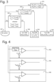
- FIG. 3 shows a flowchart of a process of the control unit 110 of the LV circuit of FIG. 2 .
- the control unit 110 is configured to receive at least one indication of a regenerative energy from the first EPAS circuit 122 and the second EPAS circuit 132.
- This indication comprises a rate of voltage change over time (dV/dt) and a voltage (V). That is, the control unit receives, from the first subcircuit 120, an indication of a first rate of voltage change over time (dV 1 /dt) and a first voltage (V 1 ), and from the second subcircuit 130, an indication of a second rate of voltage change over time (dV 2 /dt) and a second voltage (V 2 ).
- the control unit 110 is configured to check whether the first rate (dV 1 /dt) is larger than a first rate threshold (m 1 ) and the second rate (dV 2 /dt) is larger than a second rate threshold (m 2 ).
- the process continues at step 307.
- the first rate threshold (m 1 ) and the second rate threshold (m 2 ) are set to be lower than a rate limit of corresponding subcircuit.
- the control unit 110 is configured to send corresponding control signals to switch ON the first B2B MOSFET 141, the second B2B MOSFET 142, the first load switch 154 and the second load switch 164.
- the control unit 110 By turning ON the first B2B MOSFET 141, the second B2B MOSFET 142, the first load switch 154 and the second load switch 164, the regenerative energy of the at least one EPAS motor is absorbed by the first load 152 and second load 162.
- the control unit 110 is configured to check whether the first voltage (V 1 ) is larger than a first reference threshold for V 1 (V 1ref1 ) and the second voltage (V 2 ) is larger than a first reference threshold for V 2 (V 2ref1 ).
- the control unit 110 is configured to send corresponding control signals to switch ON at least one of the first load switch 154 and the second load switch 164.
- the control unit 110 is configured to send a control signal to switch ON the first load switch 154.
- the control unit 110 is configured to send a control signal to switch ON the second load switch 164.
- the control unit 110 is configured to check whether the first voltage (V 1 ) is larger than a second reference threshold for V 1 (V 1ref2 ) and the second voltage (V 2 ) is larger than a second reference threshold for V 2 (V 2ref2 ).
- the first reference threshold for V 1 (V 1ref1 ) is larger than the second reference threshold for V 1 (V 1ref2 ), that is V 1ref2 ⁇ V 1ref1 ; and the first reference threshold for V 2 (V 2ref1 ) is larger than the second reference threshold for V 2 (V 2ref2 ), that is, V 2ref2 ⁇ V 2ref1 .
- V 1ref1 and V 2ref1 should both be lower than the over voltage (OV) limit of corresponding subcircuit.
- the control unit 110 is configured to send corresponding control signals to switch ON the first B2B MOSFET 141 and the second B2B MOSFET 142.
- the control unit 110 By turning ON the first B2B MOSFET 141 and the second B2B MOSFET 142, the regenerative energy of the at least one EPAS motor is absorbed by the capacitor of the at least one of EPAS circuit.
- steps 301, 303 and 305 can be simultaneously performed.
- control unit 110 is configured to not send control signals for switching ON any of the first B2B MOSFET 141, the second B2B MOSFET 142, the first load switch 154 and the second load switch 164.
- the three conditions are:
- FIG. 4 shows a diagram circuit of a control unit according to the invention, for example the control unit 110 of FIG. 2 .
- the control unit 110 comprises a slope detection circuit 402, a first comparator 404 and a second comparator 406.
- the slope detection circuit 402 comprises a high pass filter and a comparator.
- the high pass filter allows for detecting a high rate of voltage change over time.
- the comparator is configured to compare the detected high rate of a corresponding subcircuit and corresponding rate threshold, and output a binary signal indicating which one is larger.
- the first comparator circuit 404 comprises a comparator configured to compare the indicated voltage (V) of a corresponding subcircuit and corresponding first reference threshold, and output a binary signal indicating which one is larger. In case the indicated voltage (V) is larger than the first reference threshold, the binary signal is "1", and in case the indicated voltage (V) is lower than the first reference threshold, the binary signal is "0".
- the second comparator circuit 406 comprises a comparator configured to compare the indicated voltage (V) of the corresponding subcircuit and corresponding second reference threshold, and output a binary signal indicating which one is larger. in case the indicated voltage (V) is larger than the second reference threshold, the binary signal is "1", and in case the indicated voltage (V) is lower than the second reference threshold, the binary signal is "0".
- any of the first comparator circuit 404 and the second comparator circuit 406 may further comprise more electronic elements.
- FIG. 5 shows a second example of a LV circuit.
- the LV circuit 100 includes a first subcircuit 120 and a second subcircuit 130 connected though two back-to back (B2B) MOSFETs.
- each subcircuit includes a DC-DC converter, a EPAS circuit and an element which includes a load and a load switch.
- each EPAS circuit further includes an amperemeter. The amperemeter is configured to detect a regenerative current (I) of the EPAS motor.
- the control unit 110 is configured to receive an indication of a voltage (V) of each EPAS circuit. However, instead of receiving an indication of a rate of voltage change over time (dV/dt) of each circuit as in the first example (see FIG.2 ), the control unit 110 of the second example, as shown in FIG. 5 , is configured to receive an indication of the current (I) of the EPAS circuit. That is, the control unit 110 is configured to receive, from the first subcircuit 120, an indication of a first current (I 1 ) and a first voltage (V 1 ), and from the second subcircuit 130, an indication of a current (I 2 ) and a second voltage (V 2 ).
- each DC-DC converter is connected to a corresponding EPAS circuit and element through a driving switch circuit 171,172 which comprises a switch and a diode, wherein the switch is always ON when the electric vehicle is in a driving mode, otherwise it is in OFF.
- FIG. 6 shows a flowchart of a process of the control unit 110 of the LV circuit of FIG. 5 .
- a process of the control unit 110 of the LV circuit of FIG. 5 is similar to the process in FIG. 3 .
- the control unit 110 is configured to check whether the first current (I 1 ) is larger than a first current threshold (I ref1 ) and the second current (I 2 ) is larger than a second current threshold (I ref2 ).
- the process continues at step 607.
- the first current threshold (I ref1 ) and the second current threshold (I ref2 ) are set to be lower than a current limit of corresponding subcircuit.
- the control unit 110 is configured to send corresponding control signals to switch ON the first B2B MOSFET 141, the second B2B MOSFET 142, the first load switch 154 and the second load switch 164.
- the control unit 110 By turning ON the first B2B MOSFET 141, the second B2B MOSFET 142, the first load switch 154 and the second load switch 164, the regenerative energy of the at least one EPAS motor is absorbed by the first load 152 and second load 162.
- the control unit 110 is configured to perform a check on whether the first voltage (V 1 ) is larger than a first reference threshold for V 1 (V 1ref1 ) and the second voltage (V 2 ) is larger than a first reference threshold for V 2 (V 2ref1 ).
- the control unit 110 is configured to send corresponding control to switch ON at least one of the first load switch 154 and the second load switch 164.
- the control unit 110 is configured to send a control signal to switch ON the first load switch 154.
- the control unit 110 is configured to send a control signal to switch ON the second load switch 164.
- the control unit 110 is configured to check whether the first voltage (V 1 ) is larger than a second reference threshold for V 1 (V 1ref2 ) and the second voltage (V 2 ) is larger than a second reference threshold for V 2 (V 2ref2 ).
- the first reference threshold for V 1 (V 1ref1 ) is larger than the second reference threshold for V 1 (V 1ref2 ), that is V 1ref2 ⁇ V 1ref1 ; and the first reference threshold for V 2 (V 2ref1 ) is larger than the second reference threshold for V 2 (V 2ref2 ), that is, V 2ref2 ⁇ V 2ref1 .
- V 1ref1 and V 2ref1 should be both lower than the over voltage (OV) limit of the corresponding subcircuit.
- control unit 110 is configured to send corresponding control signals to switch ON only the first B2B MOSFET 141 and the second B2B MOSFET 142.
- the control unit 110 By turning ON only the first B2B MOSFET 141 and the second B2B MOSFET 142, the regenerative energy of the at least one EPAS motor is absorbed by the capacitor of the at least one of EPAS circuits.
- control unit 110 is configured to not send control signals for switching ON any of the first B2B MOSFET 141, the second B2B MOSFET 142, the first load switch 154 and the second load switch 164.
- the three conditions are:
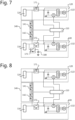
- FIG. 7 shows a third example of a LV circuit.
- the LV circuit 100 includes a first subcircuit 120 and a second subcircuit 130 connected though two back-to back (B2B) MOSFETs.
- each subcircuit includes a DC-DC converter and a EPAS circuit with an amperemeter.
- the first subcircuit 120 and second subcircuit 130 includes a load and a load switch.
- the second subcircuit 130 includes a supercapacitor 180.
- a further driving switch circuit 173 is connected in series with the supercapacitor. This further driving switch circuit 173 is always ON when the electric vehicle is in the driving mode.
- the control unit 110 is configured to receive an indication of a current (I) through the amperemeter or a voltage (V) of each EPAS circuit. That is, the control unit 110 is configured to receive, from the first subcircuit 120, an indication of a first current (I 1 ) or a first voltage (V 1 ), and from the second subcircuit 130, an indication of a current (I 2 ) or a second voltage (V 2 ).
- the control unit 110 is configured to check whether the first current (I 1 ) is larger than a first current threshold (I ref1 ) and the second current (I 2 ) is larger than a second current threshold (I ref2 ).
- the control unit 110 When at least one of the first current (I 1 ) and the second current (I 2 ) is larger than the first current threshold (I ref1 ) and the second current threshold (I ref2 ), respectively, the control unit 110 is configured to send corresponding control signals to switch ON the first B2B MOSFET 141 and the second B2B MOSFET 142. By turning ON the first B2B MOSFET 141 and the second B2B MOSFET 142, the regenerative energy of the at least one EPAS motor is absorbed by the supercapacitor 180.
- the control unit 110 is configured to check whether the first voltage (V 1 ) is larger than a reference threshold for V 1 (V 1ref ) and the second voltage (V 2 ) is larger than a reference threshold for V 2 (V 2ref ).
- the control unit 110 When at least one of the first voltage (V 1 ) and the second voltage (V 2 ) is larger than the reference threshold for V 1 (V 1ref ) and the reference threshold for V 2 (V 2ref ), respectively, the control unit 110 is configured to send corresponding control signals to switch ON the first B2B MOSFET 141 and the second B2B MOSFET 142. By turning ON only the first B2B MOSFET 141 and the second B2B MOSFET 142, the regenerative energy of the at least one EPAS motor is absorbed by the supercapacitor 180.
- the EPAS circuit may include an amperemeter for detecting the regenerative current of the EPAS motor
- an EPAS circuit without the amperemeter is also disclosed.
- the control unit 110 instead of being configured to receive a current (I) or a voltage (V), can be configured to receive a rate of voltage change over time (dV/dt) of each EPAS circuit.
- FIG.8 shows a fourth example of a LV circuit.
- the LV circuit 100 includes a first subcircuit 120 and a second subcircuit 130 connected though two back-to back (B2B) MOSFETs.
- each subcircuit includes a DC-DC converter and a EPAS circuit with an amperemeter.
- none of the first subcircuit 120 and second subcircuit 130 includes a load and a load switch.
- the first DC-DC converter or second DC-DC converter is a bidirectional DC-DC converter.
- the control unit 110 is configured to receive an indication of a current (I) through the amperemeter or an indication of a voltage (V) of each EPAS circuit. That is, the control unit 110 is configured to receive, from the first subcircuit 120, an indication of a first current (I 1 ) or a first voltage (V 1 ), and from the second subcircuit 130, an indication of a current (I 2 ) or a second voltage (V 2 ).
- the control unit 110 is configured to check whether the first current (I 1 ) is larger than a first current threshold (I ref1 ) and the second current (I 2 ) is larger than a second current threshold (I ref2 ).
- the control unit 110 is configured to send corresponding control signals to switch ON the first B2B MOSFET 141 and the second B2B MOSFET 142.
- the control unit 110 is configured to check whether the first voltage (V 1 ) is larger than a reference threshold for V 1 (V 1ref ) and the second voltage (V 2 ) is larger than a reference threshold for V 2 (V 2ref ).
- the control unit 110 is configured to send corresponding control signals to switch ON the first B2B MOSFET 141 and the second B2B MOSFET 142.
- the bidirectional DC-DC converter By turning ON the first B2B MOSFET 141 and the second B2B MOSFET 142, the regenerative energy of the at least one EPAS motor reaches the bidirectional DC-DC converter. Then, based on the voltage sensed by the bidirectional DC-DC converter and the set point of the bidirectional DC-DC converter, the bidirectional DC-DC converter activates the reverse power flow. That is, if the voltage sensed is larger than the set point, then the bidirectional DC-DC converter activates its reverse power flow, allowing the bidirectional DC-DC converter to transfer DC voltage from the LV circuit to a HV circuit (not shown). This transferred voltage is then absorbed by a capacitor of the HV circuit of the electric vehicle.
- the EPAS circuit may include an amperemeter for detecting the regenerative current of the EPAS motor
- an EPAS circuit without the amperemeter is also disclosed.
- the control unit 110 instead of being configured to receive a current (I) or a voltage (V), can be configured to receive a rate of voltage change over time (dV/dt) of each EPAS circuit.
Landscapes
- Engineering & Computer Science (AREA)
- Power Engineering (AREA)
- Transportation (AREA)
- Mechanical Engineering (AREA)
- Dc-Dc Converters (AREA)
Priority Applications (1)
| Application Number | Priority Date | Filing Date | Title |
|---|---|---|---|
| EP23213044.3A EP4563387A1 (de) | 2023-11-29 | 2023-11-29 | Strategien zur handhabung der systemdynamik in einer batterielosen niederspannungsarchitektur eines elektrofahrzeugs |
Applications Claiming Priority (1)
| Application Number | Priority Date | Filing Date | Title |
|---|---|---|---|
| EP23213044.3A EP4563387A1 (de) | 2023-11-29 | 2023-11-29 | Strategien zur handhabung der systemdynamik in einer batterielosen niederspannungsarchitektur eines elektrofahrzeugs |
Publications (1)
| Publication Number | Publication Date |
|---|---|
| EP4563387A1 true EP4563387A1 (de) | 2025-06-04 |
Family
ID=89029820
Family Applications (1)
| Application Number | Title | Priority Date | Filing Date |
|---|---|---|---|
| EP23213044.3A Pending EP4563387A1 (de) | 2023-11-29 | 2023-11-29 | Strategien zur handhabung der systemdynamik in einer batterielosen niederspannungsarchitektur eines elektrofahrzeugs |
Country Status (1)
| Country | Link |
|---|---|
| EP (1) | EP4563387A1 (de) |
Citations (4)
| Publication number | Priority date | Publication date | Assignee | Title |
|---|---|---|---|---|
| JP2004166441A (ja) * | 2002-11-15 | 2004-06-10 | Toyoda Mach Works Ltd | 電動パワーステアリング装置 |
| JP2007015428A (ja) * | 2005-07-05 | 2007-01-25 | Toyota Motor Corp | バッテリ劣化検出装置 |
| EP1095453B1 (de) * | 1998-07-03 | 2010-04-28 | Infineon Technologies AG | Schaltungsanordnung zum ansteuern einer schaltvorrichtung zum schalten eines elektrischen verbrauchers |
| JP2018113814A (ja) * | 2017-01-13 | 2018-07-19 | トヨタ自動車株式会社 | 車両用電源システム |
-
2023
- 2023-11-29 EP EP23213044.3A patent/EP4563387A1/de active Pending
Patent Citations (4)
| Publication number | Priority date | Publication date | Assignee | Title |
|---|---|---|---|---|
| EP1095453B1 (de) * | 1998-07-03 | 2010-04-28 | Infineon Technologies AG | Schaltungsanordnung zum ansteuern einer schaltvorrichtung zum schalten eines elektrischen verbrauchers |
| JP2004166441A (ja) * | 2002-11-15 | 2004-06-10 | Toyoda Mach Works Ltd | 電動パワーステアリング装置 |
| JP2007015428A (ja) * | 2005-07-05 | 2007-01-25 | Toyota Motor Corp | バッテリ劣化検出装置 |
| JP2018113814A (ja) * | 2017-01-13 | 2018-07-19 | トヨタ自動車株式会社 | 車両用電源システム |
Similar Documents
| Publication | Publication Date | Title |
|---|---|---|
| JP6107836B2 (ja) | 電池監視装置 | |
| US8174241B2 (en) | Method of protecting electricity storage device in hybrid DC power supply system | |
| US7269535B2 (en) | Fault diagnosing apparatus for vehicle and fault diagnosing method for vehicle | |
| US8878476B2 (en) | Method for discharging charges remaining in capacitor in apparatus | |
| CN101596871B (zh) | 进行间歇受电的车辆用控制装置 | |
| US8884627B2 (en) | Apparatus for detecting short-circuit of output diode in converter | |
| US20090002903A1 (en) | Power Supply Device, Electrically-Driven Vehicle Incorporating Power Supply Device, and Method of Controlling Power Supply Device | |
| US20120039100A1 (en) | Power conversion device, method of controlling power conversion device, and vehicle with the same mounted thereon | |
| US20100289452A1 (en) | Power supply apparatus for vehicles | |
| US8148934B2 (en) | Voltage step-up/down converter | |
| US10668815B2 (en) | Brake energy recovery module | |
| US20030234634A1 (en) | Method and system for diagnosing an arm-short of a bi-directional DC/DC converter | |
| JP2013074733A (ja) | 充電制御装置 | |
| CN113824087B (zh) | 一种车载电源的过压保护电路、方法、控制器及汽车 | |
| US11949260B2 (en) | Power supply system | |
| CN111824044A (zh) | 电源系统 | |
| CN214450304U (zh) | 电动汽车的电机控制器电源装置及电动汽车 | |
| US20180029546A1 (en) | On-board vehicle electrical system having a converter and high-load consumer | |
| JP4225122B2 (ja) | 負荷駆動回路における異常監視装置 | |
| JP6187180B2 (ja) | 電力変換システム | |
| US7557555B2 (en) | Method to determine an operating characteristic of a vehicle power converter | |
| JP2008289313A (ja) | 車両制御装置 | |
| EP4563387A1 (de) | Strategien zur handhabung der systemdynamik in einer batterielosen niederspannungsarchitektur eines elektrofahrzeugs | |
| JP2008054484A (ja) | 車両用電源装置 | |
| JP2004289903A (ja) | インバータ装置 |
Legal Events
| Date | Code | Title | Description |
|---|---|---|---|
| PUAI | Public reference made under article 153(3) epc to a published international application that has entered the european phase |
Free format text: ORIGINAL CODE: 0009012 |
|
| STAA | Information on the status of an ep patent application or granted ep patent |
Free format text: STATUS: THE APPLICATION HAS BEEN PUBLISHED |
|
| AK | Designated contracting states |
Kind code of ref document: A1 Designated state(s): AL AT BE BG CH CY CZ DE DK EE ES FI FR GB GR HR HU IE IS IT LI LT LU LV MC ME MK MT NL NO PL PT RO RS SE SI SK SM TR |
|
| STAA | Information on the status of an ep patent application or granted ep patent |
Free format text: STATUS: REQUEST FOR EXAMINATION WAS MADE |
|
| 17P | Request for examination filed |
Effective date: 20251204 |