EP4563406A1 - Dispositif de réglage longitudinal et siège de véhicule - Google Patents
Dispositif de réglage longitudinal et siège de véhicule Download PDFInfo
- Publication number
- EP4563406A1 EP4563406A1 EP23213734.9A EP23213734A EP4563406A1 EP 4563406 A1 EP4563406 A1 EP 4563406A1 EP 23213734 A EP23213734 A EP 23213734A EP 4563406 A1 EP4563406 A1 EP 4563406A1
- Authority
- EP
- European Patent Office
- Prior art keywords
- decoupling
- motor
- shaft
- rail
- adjustment device
- Prior art date
- Legal status (The legal status is an assumption and is not a legal conclusion. Google has not performed a legal analysis and makes no representation as to the accuracy of the status listed.)
- Pending
Links
Images




Classifications
-
- B—PERFORMING OPERATIONS; TRANSPORTING
- B60—VEHICLES IN GENERAL
- B60N—SEATS SPECIALLY ADAPTED FOR VEHICLES; VEHICLE PASSENGER ACCOMMODATION NOT OTHERWISE PROVIDED FOR
- B60N2/00—Seats specially adapted for vehicles; Arrangement or mounting of seats in vehicles
- B60N2/02—Seats specially adapted for vehicles; Arrangement or mounting of seats in vehicles the seat or part thereof being movable, e.g. adjustable
- B60N2/0224—Non-manual adjustments, e.g. with electrical operation
- B60N2/02246—Electric motors therefor
- B60N2/02253—Electric motors therefor characterised by the transmission between the electric motor and the seat or seat parts
-
- B—PERFORMING OPERATIONS; TRANSPORTING
- B60—VEHICLES IN GENERAL
- B60N—SEATS SPECIALLY ADAPTED FOR VEHICLES; VEHICLE PASSENGER ACCOMMODATION NOT OTHERWISE PROVIDED FOR
- B60N2/00—Seats specially adapted for vehicles; Arrangement or mounting of seats in vehicles
- B60N2/02—Seats specially adapted for vehicles; Arrangement or mounting of seats in vehicles the seat or part thereof being movable, e.g. adjustable
- B60N2/0224—Non-manual adjustments, e.g. with electrical operation
- B60N2/02246—Electric motors therefor
- B60N2/02258—Electric motors therefor characterised by the mounting of the electric motor for adjusting the seat
-
- B—PERFORMING OPERATIONS; TRANSPORTING
- B60—VEHICLES IN GENERAL
- B60N—SEATS SPECIALLY ADAPTED FOR VEHICLES; VEHICLE PASSENGER ACCOMMODATION NOT OTHERWISE PROVIDED FOR
- B60N2/00—Seats specially adapted for vehicles; Arrangement or mounting of seats in vehicles
- B60N2/02—Seats specially adapted for vehicles; Arrangement or mounting of seats in vehicles the seat or part thereof being movable, e.g. adjustable
- B60N2/04—Seats specially adapted for vehicles; Arrangement or mounting of seats in vehicles the seat or part thereof being movable, e.g. adjustable the whole seat being movable
- B60N2/06—Seats specially adapted for vehicles; Arrangement or mounting of seats in vehicles the seat or part thereof being movable, e.g. adjustable the whole seat being movable slidable
- B60N2/067—Seats specially adapted for vehicles; Arrangement or mounting of seats in vehicles the seat or part thereof being movable, e.g. adjustable the whole seat being movable slidable by linear actuators, e.g. linear screw mechanisms
-
- B—PERFORMING OPERATIONS; TRANSPORTING
- B60—VEHICLES IN GENERAL
- B60N—SEATS SPECIALLY ADAPTED FOR VEHICLES; VEHICLE PASSENGER ACCOMMODATION NOT OTHERWISE PROVIDED FOR
- B60N2/00—Seats specially adapted for vehicles; Arrangement or mounting of seats in vehicles
- B60N2/02—Seats specially adapted for vehicles; Arrangement or mounting of seats in vehicles the seat or part thereof being movable, e.g. adjustable
- B60N2/04—Seats specially adapted for vehicles; Arrangement or mounting of seats in vehicles the seat or part thereof being movable, e.g. adjustable the whole seat being movable
- B60N2/06—Seats specially adapted for vehicles; Arrangement or mounting of seats in vehicles the seat or part thereof being movable, e.g. adjustable the whole seat being movable slidable
- B60N2/07—Slide construction
-
- B—PERFORMING OPERATIONS; TRANSPORTING
- B60—VEHICLES IN GENERAL
- B60N—SEATS SPECIALLY ADAPTED FOR VEHICLES; VEHICLE PASSENGER ACCOMMODATION NOT OTHERWISE PROVIDED FOR
- B60N2/00—Seats specially adapted for vehicles; Arrangement or mounting of seats in vehicles
- B60N2/02—Seats specially adapted for vehicles; Arrangement or mounting of seats in vehicles the seat or part thereof being movable, e.g. adjustable
- B60N2/04—Seats specially adapted for vehicles; Arrangement or mounting of seats in vehicles the seat or part thereof being movable, e.g. adjustable the whole seat being movable
- B60N2/06—Seats specially adapted for vehicles; Arrangement or mounting of seats in vehicles the seat or part thereof being movable, e.g. adjustable the whole seat being movable slidable
- B60N2/07—Slide construction
- B60N2/0722—Constructive details
-
- B—PERFORMING OPERATIONS; TRANSPORTING
- B60—VEHICLES IN GENERAL
- B60N—SEATS SPECIALLY ADAPTED FOR VEHICLES; VEHICLE PASSENGER ACCOMMODATION NOT OTHERWISE PROVIDED FOR
- B60N2205/00—General mechanical or structural details
- B60N2205/20—Measures for elimination or compensation of play or backlash
Definitions
- the invention relates to a longitudinal adjustment device and a vehicle seat with such a longitudinal adjustment device.
- the longitudinal adjustment device usually comprises a motor unit as a drive unit, which is held on the vehicle seat by means of a bracket.
- the motor unit is in turn movement-coupled to the rail arrangement.
- the bracket can be fastened, for example, to a movable rail of the rail arrangement, in particular to an upper rail, and thus enables the position of the drive unit and/or a shaft extending from it, in particular a drive shaft, to be secured, so that it is/are reliably connected to the rail arrangement of the longitudinal adjustment device.
- the first-mentioned object is achieved according to the invention by a longitudinal adjustment device having the features of claim 1.
- the second-mentioned object is achieved according to the invention by a vehicle seat having the features of claim 10.
- the longitudinal adjustment device comprises at least one rail arrangement with two pairs of rails, wherein each pair of rails has a first rail element and a second rail element, which are movable relative to one another.
- the longitudinal adjustment device further comprises a motor unit for driving the rail arrangement and a motor mount with a motor receiving section for the motor unit and at least one shaft receiving section for at least one shaft extending from the motor unit, in particular a drive shaft, wherein at least one decoupling element is provided between the motor mount and the motor unit, between the motor mount and the shaft, and/or between the motor mount and a movable rail element.
- the decoupling element(s) ensures that the motor unit is decoupled as a noise source.
- the invention is also based on the idea of reducing vibrations emanating from moving parts, such as the motor unit, the shaft, and/or the movable rail element of the longitudinal adjustment device, and in particular reducing or preventing the transmission or transmission of these vibrations to adjacent or neighboring components or parts of the longitudinal adjustment device. This ensures that these vibrations do not hit parts with a natural frequency in the range of an excitation frequency, so that disturbing noises can be or are suppressed.
- At least one of the decoupling elements is/are designed as a motor decoupling element, at least one of the decoupling elements as a shaft decoupling element, and/or at least one of the decoupling elements as a rail decoupling element.
- the shaft decoupling element can, for example, be designed as an indirect decoupling element for the shaft.
- the shaft decoupling element is designed as a pipe decoupling element that acoustically decouples a cladding tube or guide tube arranged around the shaft.
- the motor decoupling element, the shaft decoupling element, and the rail decoupling element can be decoupled from one another.
- the decoupling elements of the various components are not connected at their ends.
- the shaft decoupling element is not connected to the motor decoupling element or the rail decoupling element.
- the motor decoupling element is not connected to the shaft decoupling element.
- the rail decoupling element is also not connected to the shaft decoupling element.
- the number of decoupling elements can vary.
- the number of decoupling elements can vary depending on the shaft length and/or the motor length.
- a curved shaft receiving section may also require additional decoupling elements.
- the invention provides a longitudinal adjustment device in which the noise source, the motor, can be acoustically decoupled. Furthermore, all vibrations emanating from other moving parts, such as the shaft and the movable rail element, can be reduced by integrating decoupling elements, such as the shaft decoupling elements and/or the rail decoupling elements.
- decoupling elements such as the shaft decoupling elements and/or the rail decoupling elements.
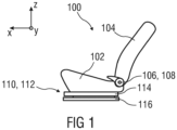
- a vehicle seat 100 schematically illustrated in the prior art is described below using three spatial directions running perpendicular to one another.
- a longitudinal direction x runs largely horizontally and preferably parallel to a vehicle longitudinal direction that corresponds to the usual direction of travel of the vehicle.
- a transverse direction y running perpendicular to the longitudinal direction x is also oriented horizontally in the vehicle and runs parallel to a vehicle transverse direction.
- a vertical direction z runs perpendicular to the longitudinal direction x and perpendicular to the transverse direction y.
- the vertical direction z preferably runs parallel to a vehicle vertical axis.
- the position and direction information used refer to a viewing direction of an occupant sitting in the vehicle seat 100 in a normal seating position, wherein the vehicle seat 100 is installed in the vehicle, in a position of use suitable for passenger transport with the backrest 104 upright and oriented in the direction of travel as usual.
- the vehicle seat 100 can also be installed or moved in a different orientation, for example, transversely to the direction of travel.
- the vehicle seat 100 is constructed mirror-symmetrically to a plane running perpendicular to the transverse direction y.
- the backrest 104 can be pivotably mounted on a seat part 102 of the vehicle seat 100.
- the vehicle seat 100 can optionally comprise a fitting 106, in particular an adjustment fitting, rotary fitting, locking fitting, or wobble fitting.
- the position and direction specifications used such as radial, axial, and circumferential, refer to a rotational axis 108 of the fitting 106.
- Radial means perpendicular to the rotational axis 108.
- Axial means in the direction of or parallel to the rotational axis 108.
- the vehicle seat 100 can optionally include a longitudinal adjustment device 110.
- the longitudinal adjustment device 110 includes, for example, a rail arrangement 112 with a first rail element 114 and a second rail element 116.
- the first rail element 114 is adjustable in the longitudinal direction x relative to the second rail element 116.
- the first rail element 114 is attached to the seat part 102.
- the second rail element 116 is attached to a structural element of a vehicle, for example, a vehicle floor.
- first rail element 114 is referred to as the upper rail 114 in the following description.
- This upper rail 114 also called a running rail or carriage
- the second rail element 116 is referred to below as the lower rail 116.
- the lower rail 116 is fixed and connected, for example, to the floor of a vehicle.
- Figure 2 shows a perspective view of the longitudinal adjustment device 110 according to the invention.
- the longitudinal adjustment device 110 comprises at least the rail arrangement 112 with two pairs of rails 112.1, 112.2.
- the respective pair of rails 112.1, 112.2 comprises the upper rail 114 as the first rail element 114 and as the second rail element 116, the lower rail 116.
- the respective upper rail 114 is movable longitudinally relative to the lower rail 116.
- the longitudinal adjustment device 110 further comprises a motor unit 120, in particular an electric motor, and a motor mount 122 for the motor unit 120 for the electromotive adjustment of the upper rail 114.
- a gear unit 124 is provided for each pair of rails 112.1, 112.2, which gear unit couples the motor unit 120 and the movable upper rail 114 of at least one of the pairs of rails 112.1, 112.2.
- the motor mount 122 has at least one motor receiving section 122.1 for the motor unit 120 and at least one shaft receiving section 122.2 for at least one shaft 126 extending from the motor unit 120, in particular a drive shaft (shown in Figure 5 ).
- the shaft 126 is in particular a flexible shaft which is guided in a sheath tube 127 (also called a guide tube).
- the motor mount 122 is attached to the upper rail 114 at attachment points 128 by means of fastening elements 128.1, for example screws.
- At least one decoupling element 130 is arranged between the motor mount 122 and the motor unit 120, between the motor mount 122 and the shaft 126, in particular the cladding tube 127, and/or between the motor mount 122 and the movable upper rail 114.
- the longitudinal adjustment device 110 comprises a combination of several decoupling elements 130.
- the respective decoupling element 130 can be designed, at least in sections, as a flexible, in particular elastic, bearing element 130.1.
- the at least one decoupling element 130 can be designed, at least in sections, as a damping, in particular vibration-damping, element 130.2.
- the decoupling elements 130 in particular the flexible bearing elements 130.1 and/or the damping elements 130.2, the transmission of structure-borne sound between the aforementioned components, in particular between the motor mount 122 and the motor unit 120, between the motor mount 122 and the shaft 126 and/or between the motor mount 122 and the movable upper rail 114, is inhibited.
- the motor mount 122 is designed, for example, as an elongated motor bridge or a motor support profile.
- the motor mount 122 extends, for example, between the two pairs of rails 112.1, 112.2 and connects them.
- the longitudinal adjustment device 110 is attached to the vehicle seat 100 (shown in Figure 1 ) attached.
- the motor receiving section 122.1 can, for example, be formed as a semi-cylindrical recess 122.11 that is open on one side.
- the recess 122.11 is formed to correspond to the contour and outer shape of the motor unit 120.
- the recess 122.11 can be rectangular.
- the motor unit 120 in particular an electric motor, can be inserted into the recess 122.11.
- the recess 122.11 is designed such that the motor unit 120 is releasably held in this recess 122.11 in a form-fitting and/or force-fitting manner.
- the shaft receiving section 122.2 borders on one or both sides of the motor receiving section 122.1 and extends to the rail pair 112.1, 112.2.
- the shaft receiving section 122.2 can, for example, be channel-shaped to receive the shaft 126 (shown in Figure 5 ) which is guided in the cladding tube 127.
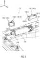
- Figure 3 shows an enlarged section in the area of the motor mounting section 122.1 of the motor mount 122 of the longitudinal adjustment device 110 according to Figure 2 and in exploded view two decoupling elements 130.
- the respective decoupling element 130 can, for example, have at least one guide section 130.3 and one decoupling section 130.4.
- the guide section 130.3 can be designed, for example, as a guide profile or a guide tube, cladding tube, or the like.
- the guide section 130.3 is designed, for example, to guide a motor end 134 or the shaft 126 extending from the motor unit 120 (shown in Figure 6 ).
- the guide section 130.3 can be designed as a through opening.
- the decoupling elements 130 are provided at each longitudinal end of the motor unit 120 and are designed as motor decoupling elements 130.5.
- the respective motor decoupling element 130.5 can, for example, be configured to decouple, in particular acoustically, the motor unit 120 radially and/or axially, in particular in the transverse direction y, from the motor mount 122, in particular the motor bridge.
- At least the decoupling section 130.4 designed as a flange 130.41, can be formed from an elastic material, in particular an elastic plastic, for example, an elastomer or rubber.
- the respective decoupling element 130 also as described below, is formed entirely from an elastic material that is sufficiently strong and stable to accommodate and guide the component to be accommodated, in particular the motor unit 120, the shaft 126, and/or the movable upper rail 114.
- Figure 4 shows the representation according to Figure 3 with built-in decoupling elements 130 designed as motor decoupling elements 130.5.
- the motor unit 120 is arranged in the motor receiving section 122.1 in a form-fitting and/or force-fitting manner and is held releasably.
- One of the motor decoupling elements 130.5 is arranged in each transition section 122.3.
- the decoupling section 130.4 of the respective motor decoupling element 130.5 is designed, for example, as a flange 130.41.
- the decoupling section 130.4 is designed, in particular, as a flexible flange 130.41.
- the flange 130.41 can, for example, be formed as an edge protruding at a right angle from the guide section 130.3.
- the guide section 130.3 can have an outer shape adapted to the motor mount 122, in particular a round or square outer shape, or a partially round and partially straight outer shape.
- the flexible flange 130.41 can be configured both for connection to the motor unit 120 and for acoustic decoupling of the motor unit 120 from the motor mount 122.
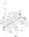
- Figure 5 shows an enlarged section in the area of the shaft receiving section 122.2 of the motor mount 122 of the longitudinal adjustment device 110 according to Figure 2 .
- the shaft 126 is designed as a flexible shaft and is coupled to an output element of the motor unit 120 (not shown in detail) via the motor decoupling element 130.5.
- a plurality of decoupling elements 130 configured as shaft decoupling elements 130.6 can be provided.
- the plurality of shaft decoupling elements 130.6 can, for example, be configured to be axially connected to one another in a form-fitting and/or force-fitting and detachable manner.
- the plurality of shaft decoupling elements 130.6 are identical or identically configured.
- the shaft decoupling elements 130.6 in particular their decoupling sections 130.4 configured as a flexible flange 130.41, decouple the shaft 126 radially and/or axially from the motor mount 122, in particular acoustically.
- the plurality of similar shaft decoupling elements 130.6 can be axially connected to one another via the flexible flanges 130.41.
- the respective flange 130.41 of one decoupling element 130 abuts against a front end of the guide section 130.3 of an adjacent decoupling element. 130 are flush with each other and/or they are partially inserted into each other.
- the shaft receiving section 122.2 has flange receptacles 122.21 that correspond to the flanges 130.41.
- the flanges 130.41 are arranged in the flange receptacles 122.21 in a form-fitting and/or force-fitting manner and are releasably held.
- the guide section(s) 130.3 of the shaft decoupling elements 130.6 can form the cladding tube 127 for the shaft 126, for example, as a single-piece or multi-piece guide tube.
- the decoupling sections 130.4 can be arranged as separate, particularly annular, damping elements on the cladding tube 127 at regular intervals.
- the cladding tube 127 and/or the end guide sections 130.3 are decoupled from the motor bridge or motor mount 122 by means of the decoupling sections 130.4, which are designed as flanges 130.41.
- Figure 6 shows the shaft receiving section 122.2 according to Figure 2 in a side view and obliquely from above.
- the shaft decoupling elements 130.6 are each designed, for example, as a sleeve 127 (also called a guide tube or guide sleeve) for receiving, guiding, and supporting the shaft 126.
- the shaft 126 can, in particular, be a so-called flexible shaft.
- the motor mount 122 is designed as a profiled body, in particular an engine bridge.
- the motor mount 122 is designed, for example, as a U-shaped profile with stiffening elements 136, for example, ribs.
- the shaft receiving section 122.2 is designed as a semi-open channel in which the shaft decoupling elements 130.6 are arranged, in which the shaft 126 is guided and rotatably mounted.
- the shaft 126 is acoustically decoupled from the motor mount 122 by means of the flanges 130.41.
- a fastening flange 138 for fastening to the motor unit 120 is provided at the end of the shaft decoupling element 130.6 facing the motor unit 120.
- Figure 7 shows an enlarged section of the fastening flange 138.
- the fastening flange 138 has an outer shape that corresponds to the shape of the channel-shaped shaft receiving section 122.2.
- Figure 8 shows an enlarged section in the area of the shaft decoupling element 130.6.
- the flange 130.41 is held in the flange receptacle 122.21 of the shaft receiving section 122.2 in a form-fitting and/or force-fitting manner.
- the guide section 130.3 is channel-shaped.
- the guide section 130.3 has, in particular, internal dimensions that correspond to the external dimensions of the shaft 126.
- Figure 9 shows a perspective sectional view of one of the rail pairs 112.1 in the area of a decoupling element 130 designed as a rail decoupling element 130.7, which acoustically decouples the movable upper rail 114 from the motor mount 122 at the fastening point 128.
- Figure 10 shows an enlarged perspective sectional view of the rail decoupling element 130.7 according to Figure 9 .
- the motor mount 122 is connected to the movable upper rail 114 by means of a fastening element 128.1, in particular a screw.
- the rail decoupling element 130.7 is designed as a flexible or elastic bearing element 130.1, for example, made of an elastic plastic material or rubber or the like.
- the rail decoupling element 130.7 is arranged in a fastening opening 114.1 of the upper rail 114 for the fastening element 128.1 and has the guide section 130.3 and decoupling sections 130.4.
- Each of the decoupling elements 130 presented here for example the motor decoupling elements 130.5, the shaft decoupling elements 130.6, the rail decoupling elements 130.7, reduces the loudness in the respective vehicle seat 100 by approximately 0.5 sone compared to seat longitudinal adjusters of conventional design.
- the various decoupling elements 130 in particular the motor decoupling elements 130.5 from the shaft decoupling elements 130.6, and these shaft decoupling elements 130.6 from the rail decoupling elements 130.7, are decoupled from one another.
- the shaft decoupling elements 130.6 of the flexible shaft 126 also called a flex shaft
- the shaft decoupling elements 130.6 are thus also completely decoupled from the motor mount 122 and the other adjacent components/assemblies via the flexible flanges 130.41.
- the structure-borne noise excitation of the motor unit 120 is reduced by mounting the motor of the motor unit 120 in the decoupling elements 130, designed as flexible bearing elements 130.1, for example, rubber elements.
- the choice of Shore hardness and the thickness of the material of the decoupling elements 130, for example, an elastomer, are tailored to reduce incoming frequencies, particularly incoming structure-borne noise due to moving parts.
- Both the decoupling elements 130 in particular those for the motor unit 120 and the other decoupling elements 130 for the shaft 126 and the upper rail 114, combine spring properties and damping properties that are or can be optimally matched to the occurring vibration frequencies.
- the number of decoupling elements 130 can be selected depending on the size, in particular the dimensions, of the longitudinal adjustment device 110, in particular the Shaft 126 and its length (also called flexible shaft length or sheath length) may vary. A curved shape of the shaft 126 or a surrounding sheath may also require additional support via these flexible flanges 130.41.
- decoupling elements 130 designed as motor decoupling elements 130.5, shaft decoupling elements 130.6 and/or rail decoupling elements 130.7, it is possible to reduce the loudness of the longitudinal adjustment device 110 to less than 1.8 sone on the vehicle seat 100, in particular an upholstered seat with measurement of the acoustics at the head.
Landscapes
- Engineering & Computer Science (AREA)
- Aviation & Aerospace Engineering (AREA)
- Transportation (AREA)
- Mechanical Engineering (AREA)
- Seats For Vehicles (AREA)
Priority Applications (3)
| Application Number | Priority Date | Filing Date | Title |
|---|---|---|---|
| EP23213734.9A EP4563406A1 (fr) | 2023-12-01 | 2023-12-01 | Dispositif de réglage longitudinal et siège de véhicule |
| CN202411711885.6A CN120080776A (zh) | 2023-12-01 | 2024-11-27 | 纵向调节装置及车辆座椅 |
| US18/961,583 US20250178487A1 (en) | 2023-12-01 | 2024-11-27 | Longitudinal adjustment device and vehicle seat |
Applications Claiming Priority (1)
| Application Number | Priority Date | Filing Date | Title |
|---|---|---|---|
| EP23213734.9A EP4563406A1 (fr) | 2023-12-01 | 2023-12-01 | Dispositif de réglage longitudinal et siège de véhicule |
Publications (1)
| Publication Number | Publication Date |
|---|---|
| EP4563406A1 true EP4563406A1 (fr) | 2025-06-04 |
Family
ID=89073365
Family Applications (1)
| Application Number | Title | Priority Date | Filing Date |
|---|---|---|---|
| EP23213734.9A Pending EP4563406A1 (fr) | 2023-12-01 | 2023-12-01 | Dispositif de réglage longitudinal et siège de véhicule |
Country Status (3)
| Country | Link |
|---|---|
| US (1) | US20250178487A1 (fr) |
| EP (1) | EP4563406A1 (fr) |
| CN (1) | CN120080776A (fr) |
Citations (5)
| Publication number | Priority date | Publication date | Assignee | Title |
|---|---|---|---|---|
| FR2808484A1 (fr) * | 2000-05-05 | 2001-11-09 | Faure Bertrand Equipements Sa | Dispositif de reglage motorise pour siege de vehicule |
| FR2883810A1 (fr) * | 2005-04-04 | 2006-10-06 | Faurecia Sieges Automobile | Ensemble de glissieres et siege comportant un tel ensemble de glissieres |
| DE102009004365A1 (de) * | 2008-01-08 | 2009-07-09 | C. Rob. Hammerstein Gmbh & Co. Kg | Motorische Längsverstellvorrichtung eines Kraftfahrzeugsitzes |
| DE102014219206A1 (de) * | 2013-09-30 | 2015-04-02 | Toyota Boshoku Kabushiki Kaisha | Verkehrsmittelsitz |
| DE102017213881A1 (de) * | 2016-08-09 | 2018-02-15 | Adient Luxembourg Holding S.à.r.l. | Antrieb für eine Längsverstellung eines Fahrzeugsitzes und Fahrzeugsitz |
Family Cites Families (23)
| Publication number | Priority date | Publication date | Assignee | Title |
|---|---|---|---|---|
| DE19844524C1 (de) * | 1998-09-29 | 2000-02-17 | Daimler Chrysler Ag | Fahrzeugsitz |
| FR2803802B1 (fr) * | 2000-01-18 | 2002-03-29 | Faure Bertrand Equipements Sa | Embase pour siege de vehicule et siege comportant une telle embase |
| US7070155B2 (en) * | 2002-11-15 | 2006-07-04 | Dura Global Technologies, Inc. | Power seat drive motor mounting arrangement and assembly method |
| US20080197654A1 (en) * | 2006-12-04 | 2008-08-21 | Johnson Controls Technology Company | Forward mounted power drive assembly |
| FR2924646B1 (fr) * | 2007-12-11 | 2010-09-24 | Faurecia Sieges Automobile | Ensemble de glissieres, siege comportant un tel ensemble de glissieres et organe support pour un tel ensemble de glissieres |
| US8245994B2 (en) * | 2009-01-29 | 2012-08-21 | Aisin Seiki Kabushiki Kaisha | Seat apparatus for vehicle |
| JP5332903B2 (ja) * | 2009-05-26 | 2013-11-06 | アイシン精機株式会社 | パワーシートの減速装置 |
| JP5471132B2 (ja) * | 2009-08-04 | 2014-04-16 | アイシン精機株式会社 | 車両用シートスライド装置 |
| WO2011027716A1 (fr) * | 2009-09-04 | 2011-03-10 | アイシン精機 株式会社 | Appareil de coulissement de siège pour véhicule |
| US8540203B2 (en) * | 2009-12-16 | 2013-09-24 | Keiper Gmbh & Co. Kg | Longitudinal adjuster for a vehicle seat with spindle and spindle holder |
| WO2011143173A1 (fr) * | 2010-05-11 | 2011-11-17 | Creative Seating Technologies, LLC | Ensemble glissière de siège de véhicule possédant un mécanisme d'entraînement à une seule courroie crantée |
| DE102012100715B4 (de) * | 2011-07-16 | 2014-12-11 | Brose Fahrzeugteile Gmbh & Co. Kommanditgesellschaft, Coburg | Verstellsystem für einen mit zwei Schienen verbundenen und mit beiden Schienen verschiebbaren Kraftfahrzeugsitz |
| JP6140545B2 (ja) * | 2013-06-20 | 2017-05-31 | トヨタ紡織株式会社 | 乗物用シートのパワースライド装置 |
| JP6250349B2 (ja) * | 2013-09-30 | 2017-12-20 | トヨタ紡織株式会社 | 乗物用シート |
| JP6282560B2 (ja) * | 2014-08-28 | 2018-02-21 | トヨタ紡織株式会社 | 乗物用シートのスライドレール |
| JP6529753B2 (ja) * | 2014-08-30 | 2019-06-12 | 株式会社デルタツーリング | パワーシートスライド装置及び乗物用シート |
| JP6614028B2 (ja) * | 2016-05-20 | 2019-12-04 | トヨタ紡織株式会社 | シートクッション調整装置 |
| DE102016225835A1 (de) * | 2016-09-21 | 2018-03-22 | Adient Luxembourg Holding S.a.r.l. | Einstellvorrichtung für einen fahrzeugsitz, sowie verfahren zur montage einer einstellvorrichtung |
| JP6756948B2 (ja) * | 2016-09-26 | 2020-09-16 | デルタ工業株式会社 | パワーシートスライド装置 |
| DE102017101996A1 (de) * | 2017-02-01 | 2018-08-02 | Ims Gear Se & Co. Kgaa | Verstellvorrichtung zum Verstellen eines Fahrzeugsitzes entlang einer Verschiebeachse |
| JP7079403B2 (ja) * | 2017-10-20 | 2022-06-02 | テイ・エス テック株式会社 | 車両用シート |
| US11332046B2 (en) * | 2019-08-22 | 2022-05-17 | Ford Global Technologies, Llc | Rail assembly having a carriage assembly |
| DE102020110442A1 (de) * | 2020-02-04 | 2021-08-05 | Adient Engineering and IP GmbH | Längseinsteller und fahrzeugsitz |
-
2023
- 2023-12-01 EP EP23213734.9A patent/EP4563406A1/fr active Pending
-
2024
- 2024-11-27 US US18/961,583 patent/US20250178487A1/en active Pending
- 2024-11-27 CN CN202411711885.6A patent/CN120080776A/zh active Pending
Patent Citations (5)
| Publication number | Priority date | Publication date | Assignee | Title |
|---|---|---|---|---|
| FR2808484A1 (fr) * | 2000-05-05 | 2001-11-09 | Faure Bertrand Equipements Sa | Dispositif de reglage motorise pour siege de vehicule |
| FR2883810A1 (fr) * | 2005-04-04 | 2006-10-06 | Faurecia Sieges Automobile | Ensemble de glissieres et siege comportant un tel ensemble de glissieres |
| DE102009004365A1 (de) * | 2008-01-08 | 2009-07-09 | C. Rob. Hammerstein Gmbh & Co. Kg | Motorische Längsverstellvorrichtung eines Kraftfahrzeugsitzes |
| DE102014219206A1 (de) * | 2013-09-30 | 2015-04-02 | Toyota Boshoku Kabushiki Kaisha | Verkehrsmittelsitz |
| DE102017213881A1 (de) * | 2016-08-09 | 2018-02-15 | Adient Luxembourg Holding S.à.r.l. | Antrieb für eine Längsverstellung eines Fahrzeugsitzes und Fahrzeugsitz |
Also Published As
| Publication number | Publication date |
|---|---|
| CN120080776A (zh) | 2025-06-03 |
| US20250178487A1 (en) | 2025-06-05 |
Similar Documents
| Publication | Publication Date | Title |
|---|---|---|
| EP3515754B1 (fr) | Dispositif de réglage pour un siège de véhicule, ainsi que procédé pour le montage d'un dispositif de réglage | |
| DE102019111242A1 (de) | Linearaktuator für einen Kraftfahrzeugsitz | |
| EP2655918B1 (fr) | Dispositif de logement amortissant les vibrations | |
| DE4325996C2 (de) | Verstellvorrichtung für eine motorisch einstellbare Kopfstütze eines Kraftfahrzeugs | |
| EP2133233A2 (fr) | Agencement de palier de broche pour un mécanisme de réglage de longueur de siège | |
| DE2731675A1 (de) | Hubschrauberrotor | |
| DE102015212408A1 (de) | Halterung mit mehreren Dämpfungselementen | |
| DE10115243B4 (de) | Fahrzeugsitz mit Lagervorrichtung | |
| DE102020102867B4 (de) | Längseinsteller für einen fahrzeugsitz und fahrzeugsitz | |
| EP4103428B1 (fr) | Dispositif de réglage avant-arrière de siège pour un siège, en particulier pour un siège de véhicule et siège de véhicule | |
| DE102004048228B4 (de) | Einstellvorrichtung mit Spindelantrieb, Schiene, umfassend eine derartige Einstellvorrichtung und Sitz, umfassend eine solche Schiene | |
| DE102022211556A1 (de) | Längseinsteller für einen Fahrzeugsitz sowie Fahrzeugsitz | |
| DE102020202523A1 (de) | Verstelleinrichtung für einen Fahrzeugsitz | |
| DE102018100425A1 (de) | Fahrzeugsitz | |
| DE102010002159B4 (de) | Vorrichtung zum Verbinden einer Antriebseinheit für eine Verstelleinrichtung eines Kraftfahrzeugsitzes mit der Festigkeitsstruktur des Kraftfahrzeugsitzes | |
| DE102006006994A1 (de) | Fahrzeugsitz | |
| DE102014225822A1 (de) | Schwingungsdämpfungseinrichtung | |
| DE10200985A1 (de) | Flexible Welle für eine Verstellvorrichtung eines Kraftfahrzeugs, insbesondere für eine Sitzverstellvorrichtung | |
| DE102011013563A1 (de) | Fahrzeugsitz, insbesondere Kraftfahrzeugsitz | |
| DE102020128521B4 (de) | Spindelgetriebe, längseinsteller, fahrzeugsitz | |
| DE102008027404B4 (de) | Schwingungstilger für eine Welle | |
| WO2006125568A1 (fr) | Dispositif pour monter une unite supplementaire dans le compartiment moteur d'une automobile | |
| DE102024209960A1 (de) | Motoradapter und einstellvorrichtung | |
| DE102023200134A1 (de) | Sitzlängsverstellung für einen Fahrzeugsitz | |
| US20250178487A1 (en) | Longitudinal adjustment device and vehicle seat |
Legal Events
| Date | Code | Title | Description |
|---|---|---|---|
| PUAI | Public reference made under article 153(3) epc to a published international application that has entered the european phase |
Free format text: ORIGINAL CODE: 0009012 |
|
| STAA | Information on the status of an ep patent application or granted ep patent |
Free format text: STATUS: THE APPLICATION HAS BEEN PUBLISHED |
|
| AK | Designated contracting states |
Kind code of ref document: A1 Designated state(s): AL AT BE BG CH CY CZ DE DK EE ES FI FR GB GR HR HU IE IS IT LI LT LU LV MC ME MK MT NL NO PL PT RO RS SE SI SK SM TR |
|
| STAA | Information on the status of an ep patent application or granted ep patent |
Free format text: STATUS: REQUEST FOR EXAMINATION WAS MADE |
|
| 17P | Request for examination filed |
Effective date: 20251204 |