EP4563424A1 - Kombinierter betriebsbrems- und feststellbremszylinder sowie pneumatische oder elektropneumatische fahrzeugbremse - Google Patents
Kombinierter betriebsbrems- und feststellbremszylinder sowie pneumatische oder elektropneumatische fahrzeugbremse Download PDFInfo
- Publication number
- EP4563424A1 EP4563424A1 EP23213483.3A EP23213483A EP4563424A1 EP 4563424 A1 EP4563424 A1 EP 4563424A1 EP 23213483 A EP23213483 A EP 23213483A EP 4563424 A1 EP4563424 A1 EP 4563424A1
- Authority
- EP
- European Patent Office
- Prior art keywords
- parking brake
- brake
- brake cylinder
- service brake
- piston
- Prior art date
- Legal status (The legal status is an assumption and is not a legal conclusion. Google has not performed a legal analysis and makes no representation as to the accuracy of the status listed.)
- Pending
Links
Images





Classifications
-
- B—PERFORMING OPERATIONS; TRANSPORTING
- B60—VEHICLES IN GENERAL
- B60T—VEHICLE BRAKE CONTROL SYSTEMS OR PARTS THEREOF; BRAKE CONTROL SYSTEMS OR PARTS THEREOF, IN GENERAL; ARRANGEMENT OF BRAKING ELEMENTS ON VEHICLES IN GENERAL; PORTABLE DEVICES FOR PREVENTING UNWANTED MOVEMENT OF VEHICLES; VEHICLE MODIFICATIONS TO FACILITATE COOLING OF BRAKES
- B60T17/00—Component parts, details, or accessories of power brake systems not covered by groups B60T8/00, B60T13/00 or B60T15/00, or presenting other characteristic features
- B60T17/08—Brake cylinders other than ultimate actuators
- B60T17/085—Spring loaded brake actuators
- B60T17/086—Spring loaded brake actuators with emergency release device
-
- B—PERFORMING OPERATIONS; TRANSPORTING
- B60—VEHICLES IN GENERAL
- B60T—VEHICLE BRAKE CONTROL SYSTEMS OR PARTS THEREOF; BRAKE CONTROL SYSTEMS OR PARTS THEREOF, IN GENERAL; ARRANGEMENT OF BRAKING ELEMENTS ON VEHICLES IN GENERAL; PORTABLE DEVICES FOR PREVENTING UNWANTED MOVEMENT OF VEHICLES; VEHICLE MODIFICATIONS TO FACILITATE COOLING OF BRAKES
- B60T13/00—Transmitting braking action from initiating means to ultimate brake actuator with power assistance or drive; Brake systems incorporating such transmitting means, e.g. air-pressure brake systems
- B60T13/10—Transmitting braking action from initiating means to ultimate brake actuator with power assistance or drive; Brake systems incorporating such transmitting means, e.g. air-pressure brake systems with fluid assistance, drive, or release
- B60T13/24—Transmitting braking action from initiating means to ultimate brake actuator with power assistance or drive; Brake systems incorporating such transmitting means, e.g. air-pressure brake systems with fluid assistance, drive, or release the fluid being gaseous
- B60T13/26—Compressed-air systems
- B60T13/261—Compressed-air systems systems with both indirect application and application by springs or weights and released by compressed air
-
- B—PERFORMING OPERATIONS; TRANSPORTING
- B60—VEHICLES IN GENERAL
- B60T—VEHICLE BRAKE CONTROL SYSTEMS OR PARTS THEREOF; BRAKE CONTROL SYSTEMS OR PARTS THEREOF, IN GENERAL; ARRANGEMENT OF BRAKING ELEMENTS ON VEHICLES IN GENERAL; PORTABLE DEVICES FOR PREVENTING UNWANTED MOVEMENT OF VEHICLES; VEHICLE MODIFICATIONS TO FACILITATE COOLING OF BRAKES
- B60T17/00—Component parts, details, or accessories of power brake systems not covered by groups B60T8/00, B60T13/00 or B60T15/00, or presenting other characteristic features
- B60T17/08—Brake cylinders other than ultimate actuators
- B60T17/083—Combination of service brake actuators with spring loaded brake actuators
-
- B—PERFORMING OPERATIONS; TRANSPORTING
- B60—VEHICLES IN GENERAL
- B60T—VEHICLE BRAKE CONTROL SYSTEMS OR PARTS THEREOF; BRAKE CONTROL SYSTEMS OR PARTS THEREOF, IN GENERAL; ARRANGEMENT OF BRAKING ELEMENTS ON VEHICLES IN GENERAL; PORTABLE DEVICES FOR PREVENTING UNWANTED MOVEMENT OF VEHICLES; VEHICLE MODIFICATIONS TO FACILITATE COOLING OF BRAKES
- B60T17/00—Component parts, details, or accessories of power brake systems not covered by groups B60T8/00, B60T13/00 or B60T15/00, or presenting other characteristic features
- B60T17/08—Brake cylinders other than ultimate actuators
- B60T17/088—Mounting arrangements
Definitions
- the present invention relates to a combined service brake and parking brake cylinder according to the preamble of claim 1, and to a pneumatic or electro-pneumatic vehicle brake comprising at least one combined service brake and parking brake cylinder according to claim 14.
- Combined pneumatic service brake and parking brake cylinders with a service brake function and a parking brake function are usually arranged on rear axles of commercial vehicles and usually have two compressed air ports.
- One compressed air port controls the parking brake function and is under a parking brake release pressure for compressing an accumulator spring of the parking brake cylinder when the commercial vehicles are in a driving state.
- the other compressed air port controls the service brake function and is vented in the driving condition to brake the commercial vehicle via the service brake.
- the parking brake function is controlled by means of a usually in the form of a diaphragm cylinder. If the commercial vehicle is to be parked, the parking brake cylinder is released and the parking brake is applied via the spring tension of the accumulator spring.
- a combined service brake and parking brake cylinder is known, for example, from DE 10 2014 002 112 A1 .
- the parking brake cylinder and the service brake cylinder are arranged coaxially one behind the other and connected to each other by an intermediate flange.
- an arrangement requires a relatively long installation space within the wheel arches of the commercial vehicles, which can cause space problems.
- a combined service brake and parking brake cylinder is proposed in DE 10 2014 002 112 A1 , in which the service brake cylinder and the parking brake cylinder are placed laterally next to one another, the accumulator spring being arranged there around the service brake cylinder.
- the service brake piston is guided within the parking brake piston and axially thereon, which has a radially inwardly extending circumferential edge which abuts against an end-face annular surface of the service brake piston in order to drive the service brake piston together with the service brake piston rod into the applied position when the parking brake is applied.
- the radially inwardly extending peripheral edge of the parking brake piston is loaded by the service brake pressure in the service brake chamber, so that during service braking a force is generated at the parking brake piston directed against the parking brake release pressure in the parking brake chamber, which loads the parking brake piston in the application direction of the parking brake.
- the effective area of the parking brake piston on which the parking brake release pressure can act to hold the parking brake released is relatively small, resulting in a high required parking brake release pressure or a low spring stiffness of the accumulator spring, but with disadvantages in terms of compressed air consumption or parking brake force.
- a further problem can arise due to a leakage of compressed air from the compressed air chamber of the parking brake through the opening through which the piston rod protrudes from the brake cylinder into the brake caliper, since any excess pressure inside the brake caliper, in particular of more than 0.3 bar of overpressure, can lead to problems in the function of the disc brake.
- An object of the present invention is to provide a combined service brake and parking brake cylinder in such a way that the entry of compressed air from the parking brake chamber into the area of the brake caliper is reliably prevented.
- a combined service brake and parking brake cylinder for actuating a service brake and a parking brake has a spring loaded parking brake cylinder with an at least partially cylindrical housing, a spring loaded parking brake piston and at least one accumulator spring loading the parking brake piston in an actuating direction of the parking brake.
- the parking brake piston is displaceably guided on a radially inner circumferential surface of the parking brake cylinder.
- the parking brake piston and the housing delimit a parking brake chamber that can be ventilated by a parking brake pressure.
- the combined service brake and parking brake cylinder also has a service brake cylinder and a service brake piston, wherein the service brake cylinder and the service brake piston delimit a service brake chamber which can be acted upon and vented by a service brake pressure.
- the combined service brake and parking brake cylinder has a piston rod coupled to the service brake piston and the parking brake piston.
- the service brake cylinder is arranged radially inside the parking brake cylinder.
- the housing of the parking brake cylinder is closed at a first end face by a cover provided with an opening, into which a first end section of the piston rod protrudes.
- An annular seal is arranged between an outer circumference of the piston rod and an inner circumference of the opening in the cover.
- the seal has a first sealing segment which is designed as an annular lip that rests on an outer end face of the cover, preferably on an outer end face of a sleeve of the cover, and functions as a pressure relief valve to allow pressurized air to escape into the environment.
- the first sealing segment is designed in such a way that the annular lip prevents air from the environment from entering the interior of the brake caliper or the parking brake chamber, but is permeable to the compressed air from the parking brake chamber when excess pressure is present at the sealing lip, thus effectively preventing excessive excess pressure from entering the interior of the brake caliper.
- the seal seals the opening of the cover, which opening is open to the parking brake chamber.
- the seal has a bulbous second sealing segment adjoining the first sealing segment which, in the assembled state, bears against the outer circumference of the piston rod with a first bearing surface facing away from the first sealing segment and bears against an inner circumference of a sleeve of the cover provided at the opening of the cover and extending into the spring accumulator chamber with a second bearing surface opposite thereto.
- the through holes are aligned radially to the longitudinal axis of the piston rod.
- the seal has a bulbous third sealing segment and a cylindrical ring-shaped fourth sealing segment adjoining it, wherein the third sealing segment has an end face facing the spring storage chamber and bears with two opposing contact surfaces against the outer circumference of the piston rod on the one hand and against the inner circumference of the sleeve on the other hand, and the fourth sealing segment bears with two opposing contact surfaces against the outer circumference of the piston rod on the one hand and against the inner circumference of the sleeve on the other hand.
- the seal is formed in one piece.
- the seal is formed in several parts.
- the first and second sealing segments are combined into one component, as are the third and fourth sealing segments.
- the sleeve of the cover is made of a different material than the housing of the parking brake cylinder.
- a recess is formed in the outer end face of the cover, in which the first sealing segment of the seal lies. Such recess provides space for a deflection movement of the sealing lip as a result of compressed air impact.
- the service brake cylinder is arranged radially inside an accumulator spring chamber.
- the parking brake piston includes a central opening having a bearing allowing the piston rod and the parking brake piston to move axially relative to each other.
- a separate bottom to support the accumulator spring is therefore not necessary, which enables additional shortening of the axial length of the parking brake cylinder.
- the piston rod has the same outer diameter throughout its axial length, which avoid pressure loads on piston rod.
- a first actuating element provided to actuate a brake caliper is pivotally received in a recess at the first end of the piston rod, which enables the first actuating element to better follow the movement of a lever of a brake caliper.
- the pneumatic or electropneumatic vehicle brake according to the invention is characterized by at least one combined service brake and parking brake cylinder as described above.
- the pneumatic or electropneumatic vehicle brake comprises a brake caliper with a flange, on which the combined service brake and parking brake cylinder is mounted, wherein the outer end face of the cover of the parking brake cylinder delimiting the parking brake chamber faces the flange of the brake caliper, wherein the first sealing segment of the seal rests between the outer end face of the cover and the flange of the brake caliper and functions as a pressure relief valve to allow pressurized air to escape from the parking brake chamber or from an inner space delimited at least partially by the brake caliper into the environment.
- top, bottom, left, right, front, rear, etc. refer exclusively to the exemplary representation and position of the spring-applied parking brake cylinder, service brake cylinder, piston rod, housing, seal, cover and the like selected in the respective figures. These terms are not to be understood restrictively, i.e. these references may change due to different working positions or the mirror-symmetrical design or the like.
- a combined pneumatic service brake and parking brake cylinder 1 having a service function and a parking brake function as described hereinafter is usually arranged on a wheel of a rear axle of commercial vehicles and usually has two compressed air ports.
- a first compressed air port 24 controls the parking brake function and, in the driving state of commercial vehicles, is under a parking brake release pressure for compressing an accumulator spring 22 of a parking brake cylinder 2.
- a second compressed air port controls the service brake function and, particularly in the driving state, can be pressurized to brake the commercial vehicle via the service brake.
- the service brake function is carried out by means of a service brake cylinder 3 designed as a diaphragm cylinder or brake piston cylinder.
- the parking brake cylinder 2 is vented and the parking brake is applied via the spring tension of the accumulator spring 22.
- the pressure for the two compressed air ports 24 is generated by a solenoid valve device not shown here, which is supplied with compressed air under supply pressure from at least one compressed air supply.
- the solenoid valve device is controlled by an electronic control system.
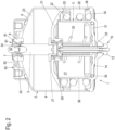
- Fig. 1 shows a perspective view of a preferred embodiment of a combined service brake and parking brake cylinder 1 of an electro-pneumatic brake system of a commercial vehicle according to the invention, looking at one end face from which a first actuating element 52 protrudes, for example for actuating a brake caliper 10 of a disc brake, can be seen.
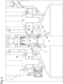
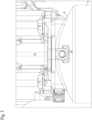
- Fig. 2 , Fig. 3 and Fig. 5 represent a cross-sectional view of the combined service brake and parking brake cylinder 1 of Fig. 1 , in a situation in which the service brake and the parking brake are released, in particular during a driving condition of the commercial vehicle, the combined service brake and parking brake cylinder 1 comprises the parking brake cylinder 2, a parking brake piston 21 axially slidably guided therein, and the accumulator spring 22 loading the parking brake piston 21 in an applied position of the parking brake.
- the parking brake cylinder 2 comprises a substantially cylindrical parking brake cylinder housing 4 with here, for example, two covers 6, 14 attached to the end faces, wherein the first actuating element 52 for the disc brake projects from a central through-opening of a first cover 6 and the second actuating element 13 of the emergency release device projects from a central through-opening of a second cover 14.
- the parking brake cylinder housing 4 could also be pot-shaped and then have, for example, only one cover.
- the parking brake cylinder housing 4 forms a closed housing of the parking brake cylinder 2, in which the service brake cylinder 3 is completely included here, for example.
- the first actuating element 52 is preferably designed as a pusher which is pivotally received in a recess 54 at the first end 53 of the piston rod 5.
- the first actuating element 52 is pivotally received in the recess 54 enabling the first actuating element 52 to follow the movement of a lever 11 of a brake caliper 10 (shown in Fig. 4 ) through deflection movement.
- the first actuating element 52 can be springloaded in a center position.
- the parking brake piston 21 is axially displaceably guided on a radially inner circumferential surface of the parking brake cylinder 2 or of the parking brake cylinder housing 4, wherein a first movement seal 25 is arranged between a radially outer edge of the parking brake piston 21 and the radially inner circumferential surface of the parking brake cylinder 2 or of the parking brake cylinder housing 4 and which, in addition to a sealing function, also performs a guide function for the parking brake piston 21.
- the parking brake piston 21 delimits a parking brake chamber 23 which can be pressurized and vented by a parking brake pressure via the first compressed air connection 24.
- the parking brake chamber 23 is filled with pressurized air in a driving state of the vehicle and vented in a parking state of the vehicle.
- the accumulator spring 22 is then supported with its one end on the other side of the parking brake piston 21, the other end of which is supported on the parking brake cylinder housing 4 in an accumulator spring chamber 26.
- the accumulator spring chamber 26 is sealed from the parking brake chamber 23 above by the first movement seal 25 and a bearing 28, which will be described in more detail further below and is therefore not pressurized and vented by the parking brake pressure.
- the first air pressure port 24 is formed, for example, in the first cover 6. However, it could also be formed in a bottom of the parking brake cylinder 2 or the parking brake cylinder housing 4 if the parking brake cylinder housing 4 is pot-shaped, for example.
- the accumulator spring 22 is accommodated in an accumulator spring chamber 26 which is formed here as an annular chamber and is radially outer with respect to the service brake cylinder 3, and which is limited or bounded radially inwardly by a radially outer circumferential surface of a service brake cylinder housing 34 of the service brake cylinder 3 and radially outwardly by the radially inner circumferential surface of the parking brake cylinder housing 4.
- the accumulator spring chamber 26 is limited or bounded by the parking brake piston 21 and the service brake cylinder housing 34.
- the service brake cylinder 3 or the service brake cylinder housing 34 directly guides an axially displaceable service brake piston 31, the service brake cylinder 3 and the service brake piston 31 delimiting a service brake chamber 33 which can be pressurized and vented with a service brake pressure via the second compressed air port (not shown).
- the service brake cylinder 3 or the service brake cylinder housing 34 of the service brake cylinder 3 is arranged radially (i.e. radially to the piston rod 5) and here, for example, also axially (i.e. axially to the piston rod 5), preferably completely within the parking brake cylinder 2 or within the parking brake cylinder housing 4 of the parking brake cylinder 2. More preferably the service brake cylinder 3 is arranged radially inside the accumulator spring chamber 26.
- the service brake piston 31 is axially slidably guided directly on the radially inner peripheral surface of the service brake cylinder 3 or the service brake cylinder housing 34.
- This direct guidance includes that a third movement seal 35 is arranged therebetween, which here is connected to the radially outer edge of the service brake piston 31 in addition to a sealing function also performs a guiding function for the service brake piston 31.
- the service brake piston 31 is connected to a piston rod 5, which is made hollow here, for example, to receive the emergency release device 15 in its interior.
- the piston rod 5 then actuates the parking brake via the first actuating element 52 when the service brake chamber 33 is pressurized with a service brake application pressure, and which releases the service brake when the service brake chamber 33 is vented.
- the end of the piston rod 5 facing the caliper 10 can then project radially outwardly away from the parking brake chamber 23 in a mushroom-like manner.
- the service brake cylinder 3 or the service brake cylinder housing 34 is here, for example, of pot-shaped design and has a cylindrical wall 36 extending in parallel into the parking brake cylinder 2 or into the parking brake cylinder housing 4, and a bottom.
- the bottom is provided, for example, with a central opening through which the parking brake piston rod 5 then projects into the parking brake cylinder 2 or into the parking brake chamber 23.
- the piston rod 5 penetrates the parking brake chamber 23 centrally and then receives the first actuating element 52 for the disc brake in a recess at its end facing the disc brake and projecting out of the parking brake cylinder housing 4 through the through-opening 61 of the first cover 6.
- a return spring chamber 37 is formed here between the service brake piston 31 and the bottom of the service brake cylinder 3, with a return spring 32 which loads the service brake piston 31 into the service brake release position. Also, the return spring chamber 37 is penetrated axially and centrally by the piston rod 5.
- the return spring chamber 37 is sealed from the service brake chamber 33 by the third movement seal 35 as described above and therefore not pressurized and vented by the service brake pressure.
- the here for example pot-shaped service brake cylinder 3 has the free edge 38 which is preferably fixed to the parking brake cylinder 2 on the inside, in particular in the region of the fixing of the end-face second cover 14 to the parking brake cylinder 2, whereby this second cover 14 also delimits or closes the service brake chamber 33.
- the service brake chamber 33 which can be ventilated and exhausted is delimited by the cylindrical wall 36 of the service brake cylinder housing 34, the second cover 14 of the parking brake cylinder 2 and the service brake piston 31 or, alternatively, by the above-mentioned diaphragm in the case a the above-mentioned diaphragm cylinder used as the service brake cylinder 3.
- the service brake cylinder 3 is arranged radially within the parking brake cylinder 2.
- the housing 4 of the parking brake cylinder 2 is closed at a first end face by a cover 6 provided with an opening 61, into which a first end section 53 of the piston rod 5 projects.
- An actuator 52 is accommodated in this first end section 53 of the piston rod 5, the free end of which, as shown in Figure 4 , engages in a dome-shaped recess of a brake lever 11 of a brake caliper 10 of a vehicle brake.
- the service brake and parking brake cylinder 1 is preferably fixed to a flange area of the brake caliper 10 with the aid of screws 12, as shown in Figure 7 as an example.
- the parking brake piston 21 further includes a central opening having a bearing 28 through which the parking brake piston 21 is axially guided on the piston rod 5.
- the bearing 28 therefore allows the piston rod 5 and the parking brake piston 21 to move axially relative to each other.
- the bearing 28 is designed, for example, as a sealing bearing.
- the parking brake piston 21 then extends, viewed radially, from the bearing 28 or from the central opening of the parking brake piston 21 beyond a radially outer circumferential surface of the service brake cylinder 3 or of the service brake cylinder housing 36 to the radially inner circumferential surface of the parking brake cylinder 2 or of the parking brake cylinder housing 4.
- the effective surface of the parking brake piston 21 on which the parking brake pressure or the parking brake release pressure acts is located on the side of the parking brake piston 21 facing the parking brake chamber 23 and then also extends from the bearing 28 to the radially inner circumferential surface of the parking brake cylinder 2 or of the parking brake cylinder housing 4.
- the first movement seal 25 arranged at the radially outer edge of the parking brake piston 21 and the bearing 28 are arranged so as to move substantially together and in parallel to the axis of the cylinder 1
- the piston rod 5 has, in particular at its radially outer periphery, a radial protrusion 27 which forms an axial stop for the bearing 28 or for the central opening of the parking brake piston 21.
- This radial protrusion 27 is arranged on the piston rod 5, for example, in such a way that the parking brake piston 21 brings the piston rod 5 into the parking brake application position by abutting against the radial protrusion 27 when the parking brake chamber 23 is vented to apply the parking brake.
- the piston rod 5 preferably has the same outer diameter throughout its axial length in order to avoid any pressure forces acting on the piston rod 5.
- the piston rod 5 can be formed in one piece with its first end section 53 and an opposite end abutting a return spring chamber 37 side of the service brake piston 31.
- the piston rod 5 can be formed in basically two pieces with a first parking brake section including the first end section 53 and ending below the radial protrusion 27, and a second service brake section having a first end mounted on an outer circumference of the protrusion 27 or the first parking brake section of piston rod 5 and an opposite end abutting the return spring chamber 37 side of the service brake piston 31.
- the parking brake section has the same outer diameter as the service brake section.
- annular seal 7 is arranged between an outer circumference 51 of the piston rod 5 and an inner circumference of the opening 61 of the cover 6.
- This seal 7 has a first sealing segment 71, which is designed as an annular lip resting on an outer end face 62 of the cover 6 and functioning as a pressure relief valve to allow pressurized air to escape from the parking brake chamber 23 into the environment.
- FIG 8 A single perspective view of a section of such a seal 7 is shown in Figure 8 .
- the seal 7 here has a bulbous second sealing segment 72 adjoining the first sealing segment 71, which in the assembled state rests against the outer circumference 51 of the piston rod 5.
- the second sealing segment 72 has a first contact surface 721 facing away from the first sealing segment 71, as can be seen in Figures 2 to 6 .
- a second abutment surface 722 opposite the first contact surface 721 abuts an inner circumference 81 of a sleeve 8 of the cover 6, provided at the opening 61 of the cover 6 and extending into the parking brake chamber 23.
- bulbous is to be understood in particular as reinforced in its material thickness relative to the web-like first sealing segment 71.
- the second sealing segment 72 protrudes into a recess in the sleeve 8 of the cover 6, with the recess extending from the surface facing the brake caliper 10 to the surface facing the piston rod 5.
- a bead 76 provided with perforations 761 is formed on a surface of the first sealing segment 71 facing the brake caliper 10, which bead protrudes from the surface facing the brake caliper 10.
- a web projects preferably at an obtuse angle from the end of the surface facing the brake caliper 10, which in the installed state rests against a counter surface of the brake caliper 10.
- the sleeve 8 as part of the cover 6 serves in particular to increase the possible contact surface of the seal 7 between the outer circumference 51 of the piston rod 5 and the cover 6.
- the sleeve 8 can be formed in one piece with the cover 6.
- the sleeve 8 of the cover 6 is designed as a separate component fixed to the remaining part of the cover 6. This enables in particular the selection of a different material for the sleeve 8 compared to the remaining part of the cover 6 as well as other manufacturing options for the sleeve 8, for example manufacturing by cold forming, hot forming or the like.
- the seal 7 preferably has a bulbous third sealing segment 73 and a cylindrical ring-shaped fourth sealing segment 74 adjoining it.
- the third sealing segment 73 has an end face 731 facing the parking brake chamber 23 and rests with two opposing contact surfaces 732, 733 on the outer circumference 51 of the piston rod 5 on the one hand and on the inner circumference 81 of the sleeve 8 on the other.
- the fourth sealing segment 74 lies with two opposing contact surfaces 741, 742 on the outer circumference 51 of the piston rod 5 on the one hand and on the inner circumference 81 of the sleeve 8 on the other.
- the four sealing segments 71, 72, 73 and 74 are shown as a one-piece component.
- sealing segments 71, 72, 73 and 74 are made up of several parts, in particular for the seal 7 to be divided into two parts, in which the first and second sealing segments 71, 72 are combined to form a one-piece segment and the third and fourth sealing segments 73, 74 are combined to form a second component.
- These through-holes 75 are preferably aligned radially to the longitudinal axis of the piston rod 5. However, it is also conceivable for the through holes 75 to be aligned at an angle to a radial axis.
- the seal 7 in particular its rigidity, is designed in such a way that it allows compressed air above a pressure of preferably 0.3 bar overpressure (i.e. 0,3 bar more than ambient air pressure) to escape into the environment.
- the compressed air can flow along the piston rod 5 and then further along the first sealing segment 71.
- the design of the first sealing segment 71 as a sealing lip enables the sealing lip to be deformed in such a way that the air can easily pass through a gap between the first sealing segment 71 and a contact surface or flange of the brake caliper 10 opposite it to the outside and into the environment, thereby preventing compressed air from entering the interior of the brake caliper 10.
- the leakage compressed air flowing along the piston rod 5 can pass through the through-holes 75 into an intermediate space created by the compressed air between the sleeve 8 and the first sealing segment 71 before reaching an end of the second sealing segment 72 close to the brake caliper 10 and from there be guided laterally into the surroundings by evasion of the first sealing segment 71, which is designed as a sealing lip.
- a recess 63 is formed in the outer end face 62 of the cover 6, in which the first sealing segment 71 of the seal 7 lies, in order to increase the possibility of the first sealing segment 71 deflecting.
Landscapes
- Engineering & Computer Science (AREA)
- Transportation (AREA)
- Mechanical Engineering (AREA)
- Braking Arrangements (AREA)
Priority Applications (2)
| Application Number | Priority Date | Filing Date | Title |
|---|---|---|---|
| EP23213483.3A EP4563424A1 (de) | 2023-11-30 | 2023-11-30 | Kombinierter betriebsbrems- und feststellbremszylinder sowie pneumatische oder elektropneumatische fahrzeugbremse |
| PCT/EP2024/079627 WO2025113884A1 (en) | 2023-11-30 | 2024-10-21 | Combined service brake and parking brake cylinder and pneumatic or electro-pneumatic vehicle brake |
Applications Claiming Priority (1)
| Application Number | Priority Date | Filing Date | Title |
|---|---|---|---|
| EP23213483.3A EP4563424A1 (de) | 2023-11-30 | 2023-11-30 | Kombinierter betriebsbrems- und feststellbremszylinder sowie pneumatische oder elektropneumatische fahrzeugbremse |
Publications (1)
| Publication Number | Publication Date |
|---|---|
| EP4563424A1 true EP4563424A1 (de) | 2025-06-04 |
Family
ID=89029770
Family Applications (1)
| Application Number | Title | Priority Date | Filing Date |
|---|---|---|---|
| EP23213483.3A Pending EP4563424A1 (de) | 2023-11-30 | 2023-11-30 | Kombinierter betriebsbrems- und feststellbremszylinder sowie pneumatische oder elektropneumatische fahrzeugbremse |
Country Status (2)
| Country | Link |
|---|---|
| EP (1) | EP4563424A1 (de) |
| WO (1) | WO2025113884A1 (de) |
Citations (6)
| Publication number | Priority date | Publication date | Assignee | Title |
|---|---|---|---|---|
| GB1508171A (en) * | 1974-03-18 | 1978-04-19 | Aeroquip Ag | Brake actuating apparatus |
| EP0490841A1 (de) * | 1990-12-13 | 1992-06-17 | Knorr-Bremse Sistemi Per Autoveicoli Commerciali S.P.A. | Doppelbremselement für Druckluftbremsanlage |
| US6588314B1 (en) * | 2000-03-15 | 2003-07-08 | Haldex Brake Corporation | Sealed brake actuator |
| US20100320039A1 (en) * | 2008-02-22 | 2010-12-23 | Knorr-Bremse Systeme Fuer Nutzfahrzeuge Gmbh | Brake Cylinder for Compressed Air Operated Vehicle Disc Brakes |
| CN103946088A (zh) * | 2011-10-07 | 2014-07-23 | 克诺尔商用车制动系统有限公司 | 带有卡口式连接机构的组合式常用制动及弹簧储能制动缸 |
| DE102014002112A1 (de) | 2014-02-15 | 2015-08-20 | Man Truck & Bus Ag | Bremszylinder für Kraftfahrzeug-Bremse |
Family Cites Families (1)
| Publication number | Priority date | Publication date | Assignee | Title |
|---|---|---|---|---|
| DE502005006340D1 (de) * | 2004-09-21 | 2009-02-05 | Knorr Bremse Systeme | Bremszylinder für fahrzeugbremsen |
-
2023
- 2023-11-30 EP EP23213483.3A patent/EP4563424A1/de active Pending
-
2024
- 2024-10-21 WO PCT/EP2024/079627 patent/WO2025113884A1/en active Pending
Patent Citations (6)
| Publication number | Priority date | Publication date | Assignee | Title |
|---|---|---|---|---|
| GB1508171A (en) * | 1974-03-18 | 1978-04-19 | Aeroquip Ag | Brake actuating apparatus |
| EP0490841A1 (de) * | 1990-12-13 | 1992-06-17 | Knorr-Bremse Sistemi Per Autoveicoli Commerciali S.P.A. | Doppelbremselement für Druckluftbremsanlage |
| US6588314B1 (en) * | 2000-03-15 | 2003-07-08 | Haldex Brake Corporation | Sealed brake actuator |
| US20100320039A1 (en) * | 2008-02-22 | 2010-12-23 | Knorr-Bremse Systeme Fuer Nutzfahrzeuge Gmbh | Brake Cylinder for Compressed Air Operated Vehicle Disc Brakes |
| CN103946088A (zh) * | 2011-10-07 | 2014-07-23 | 克诺尔商用车制动系统有限公司 | 带有卡口式连接机构的组合式常用制动及弹簧储能制动缸 |
| DE102014002112A1 (de) | 2014-02-15 | 2015-08-20 | Man Truck & Bus Ag | Bremszylinder für Kraftfahrzeug-Bremse |
Also Published As
| Publication number | Publication date |
|---|---|
| WO2025113884A1 (en) | 2025-06-05 |
Similar Documents
| Publication | Publication Date | Title |
|---|---|---|
| US4024936A (en) | Combination vehicle service and parking brake | |
| CA2373384C (en) | Sealed brake actuator | |
| US4667527A (en) | Spring-loaded brake with pressure-medium-operable lifting set | |
| JP2007062729A (ja) | 制御バルブを備えた空気式ブレーキアクチュエータ | |
| US3896706A (en) | Brake actuator units | |
| JPH0536267B2 (de) | ||
| US8196718B2 (en) | Combined service brake and stored-energy brake cylinder with internal ventilation | |
| US10626939B2 (en) | Adhesive attachment of the disc brake pushrod plate to the diaphragm | |
| US4030576A (en) | Disc brake assembly including a self-contained actuator with wear take-up and anti-drag device | |
| CN101001773A (zh) | 制动执行器 | |
| JP2009509866A (ja) | 内部空気逃し手段を備えた常用ブレーキシリンダとばね付勢ブレーキシリンダとの複合体 | |
| JPH07500070A (ja) | 車両のブレーキシステム用液圧切換弁 | |
| EP4563424A1 (de) | Kombinierter betriebsbrems- und feststellbremszylinder sowie pneumatische oder elektropneumatische fahrzeugbremse | |
| KR20130023197A (ko) | 제동력 증폭기 | |
| JPH04331828A (ja) | ディスクブレーキ | |
| US7451689B2 (en) | Combined service brake and spring brake cylinder assembly | |
| US3974897A (en) | Brake actuator assembly | |
| CN102245452B (zh) | 带有外部排气装置的弹簧储能制动缸 | |
| EP4282722B1 (de) | Kolbenmanschette für eine bremsbetätigungsvorrichtung, bremsbetätigungsvorrichtung, die eine jeweilige kolbenmanschette umfasst und eine bremsscheibe | |
| EP4286232A1 (de) | Kombinierter betriebsbrems- und federspeicherbremszylinder mit im federspeicherbremszylinder angeordnetem betriebsbremszylinder | |
| JPH0215422B2 (de) | ||
| CN112888872A (zh) | 用于汽车制动缸的改进的柔性防尘罩 | |
| US5685399A (en) | Hydraulic brake slack adjuster | |
| KR20010015676A (ko) | 자동차용 공압식 제동력 부스터 | |
| JP7727002B2 (ja) | シミュレータユニットを有する制動装置 |
Legal Events
| Date | Code | Title | Description |
|---|---|---|---|
| PUAI | Public reference made under article 153(3) epc to a published international application that has entered the european phase |
Free format text: ORIGINAL CODE: 0009012 |
|
| STAA | Information on the status of an ep patent application or granted ep patent |
Free format text: STATUS: THE APPLICATION HAS BEEN PUBLISHED |
|
| AK | Designated contracting states |
Kind code of ref document: A1 Designated state(s): AL AT BE BG CH CY CZ DE DK EE ES FI FR GB GR HR HU IE IS IT LI LT LU LV MC ME MK MT NL NO PL PT RO RS SE SI SK SM TR |
|
| STAA | Information on the status of an ep patent application or granted ep patent |
Free format text: STATUS: REQUEST FOR EXAMINATION WAS MADE |
|
| 17P | Request for examination filed |
Effective date: 20250909 |
|
| GRAP | Despatch of communication of intention to grant a patent |
Free format text: ORIGINAL CODE: EPIDOSNIGR1 |
|
| STAA | Information on the status of an ep patent application or granted ep patent |
Free format text: STATUS: GRANT OF PATENT IS INTENDED |
|
| RIC1 | Information provided on ipc code assigned before grant |
Ipc: B60T 17/08 20060101AFI20260112BHEP |
|
| INTG | Intention to grant announced |
Effective date: 20260127 |
|
| GRAS | Grant fee paid |
Free format text: ORIGINAL CODE: EPIDOSNIGR3 |
|
| GRAA | (expected) grant |
Free format text: ORIGINAL CODE: 0009210 |
|
| STAA | Information on the status of an ep patent application or granted ep patent |
Free format text: STATUS: THE PATENT HAS BEEN GRANTED |