EP4563543A1 - Verfahren und glasbehälter zur lagerung einer pharmazeutischen zusammensetzung bei einer temperatur von -80 °c oder darunter - Google Patents
Verfahren und glasbehälter zur lagerung einer pharmazeutischen zusammensetzung bei einer temperatur von -80 °c oder darunter Download PDFInfo
- Publication number
- EP4563543A1 EP4563543A1 EP23213401.5A EP23213401A EP4563543A1 EP 4563543 A1 EP4563543 A1 EP 4563543A1 EP 23213401 A EP23213401 A EP 23213401A EP 4563543 A1 EP4563543 A1 EP 4563543A1
- Authority
- EP
- European Patent Office
- Prior art keywords
- less
- coating
- stopper
- cross
- container
- Prior art date
- Legal status (The legal status is an assumption and is not a legal conclusion. Google has not performed a legal analysis and makes no representation as to the accuracy of the status listed.)
- Pending
Links
Images


Classifications
-
- A—HUMAN NECESSITIES
- A61—MEDICAL OR VETERINARY SCIENCE; HYGIENE
- A61J—CONTAINERS SPECIALLY ADAPTED FOR MEDICAL OR PHARMACEUTICAL PURPOSES; DEVICES OR METHODS SPECIALLY ADAPTED FOR BRINGING PHARMACEUTICAL PRODUCTS INTO PARTICULAR PHYSICAL OR ADMINISTERING FORMS; DEVICES FOR ADMINISTERING FOOD OR MEDICINES ORALLY; BABY COMFORTERS; DEVICES FOR RECEIVING SPITTLE
- A61J1/00—Containers specially adapted for medical or pharmaceutical purposes
- A61J1/14—Details; Accessories therefor
- A61J1/1468—Containers characterised by specific material properties
-
- C—CHEMISTRY; METALLURGY
- C03—GLASS; MINERAL OR SLAG WOOL
- C03C—CHEMICAL COMPOSITION OF GLASSES, GLAZES OR VITREOUS ENAMELS; SURFACE TREATMENT OF GLASS; SURFACE TREATMENT OF FIBRES OR FILAMENTS MADE FROM GLASS, MINERALS OR SLAGS; JOINING GLASS TO GLASS OR OTHER MATERIALS
- C03C17/00—Surface treatment of glass, not in the form of fibres or filaments, by coating
- C03C17/001—General methods for coating; Devices therefor
- C03C17/003—General methods for coating; Devices therefor for hollow ware, e.g. containers
- C03C17/004—Coating the inside
-
- B—PERFORMING OPERATIONS; TRANSPORTING
- B65—CONVEYING; PACKING; STORING; HANDLING THIN OR FILAMENTARY MATERIAL
- B65D—CONTAINERS FOR STORAGE OR TRANSPORT OF ARTICLES OR MATERIALS, e.g. BAGS, BARRELS, BOTTLES, BOXES, CANS, CARTONS, CRATES, DRUMS, JARS, TANKS, HOPPERS, FORWARDING CONTAINERS; ACCESSORIES, CLOSURES, OR FITTINGS THEREFOR; PACKAGING ELEMENTS; PACKAGES
- B65D13/00—Containers having bodies formed by interconnecting two or more rigid, or substantially rigid, components made wholly or mainly of the same material, other than metal, plastics, wood or substitutes therefor
- B65D13/02—Containers having bodies formed by interconnecting two or more rigid, or substantially rigid, components made wholly or mainly of the same material, other than metal, plastics, wood or substitutes therefor of glass, pottery, or other ceramic material
-
- A—HUMAN NECESSITIES
- A61—MEDICAL OR VETERINARY SCIENCE; HYGIENE
- A61J—CONTAINERS SPECIALLY ADAPTED FOR MEDICAL OR PHARMACEUTICAL PURPOSES; DEVICES OR METHODS SPECIALLY ADAPTED FOR BRINGING PHARMACEUTICAL PRODUCTS INTO PARTICULAR PHYSICAL OR ADMINISTERING FORMS; DEVICES FOR ADMINISTERING FOOD OR MEDICINES ORALLY; BABY COMFORTERS; DEVICES FOR RECEIVING SPITTLE
- A61J1/00—Containers specially adapted for medical or pharmaceutical purposes
- A61J1/05—Containers specially adapted for medical or pharmaceutical purposes for collecting, storing or administering blood, plasma or medical fluids ; Infusion or perfusion containers
- A61J1/06—Ampoules or carpules
- A61J1/065—Rigid ampoules, e.g. glass ampoules
-
- A—HUMAN NECESSITIES
- A61—MEDICAL OR VETERINARY SCIENCE; HYGIENE
- A61J—CONTAINERS SPECIALLY ADAPTED FOR MEDICAL OR PHARMACEUTICAL PURPOSES; DEVICES OR METHODS SPECIALLY ADAPTED FOR BRINGING PHARMACEUTICAL PRODUCTS INTO PARTICULAR PHYSICAL OR ADMINISTERING FORMS; DEVICES FOR ADMINISTERING FOOD OR MEDICINES ORALLY; BABY COMFORTERS; DEVICES FOR RECEIVING SPITTLE
- A61J1/00—Containers specially adapted for medical or pharmaceutical purposes
- A61J1/14—Details; Accessories therefor
- A61J1/1412—Containers with closing means, e.g. caps
-
- A—HUMAN NECESSITIES
- A61—MEDICAL OR VETERINARY SCIENCE; HYGIENE
- A61L—METHODS OR APPARATUS FOR STERILISING MATERIALS OR OBJECTS IN GENERAL; DISINFECTION, STERILISATION OR DEODORISATION OF AIR; CHEMICAL ASPECTS OF BANDAGES, DRESSINGS, ABSORBENT PADS OR SURGICAL ARTICLES; MATERIALS FOR BANDAGES, DRESSINGS, ABSORBENT PADS OR SURGICAL ARTICLES
- A61L31/00—Materials for other surgical articles, e.g. stents, stent-grafts, shunts, surgical drapes, guide wires, materials for adhesion prevention, occluding devices, surgical gloves, tissue fixation devices
- A61L31/08—Materials for coatings
- A61L31/10—Macromolecular materials
-
- A—HUMAN NECESSITIES
- A61—MEDICAL OR VETERINARY SCIENCE; HYGIENE
- A61M—DEVICES FOR INTRODUCING MEDIA INTO, OR ONTO, THE BODY; DEVICES FOR TRANSDUCING BODY MEDIA OR FOR TAKING MEDIA FROM THE BODY; DEVICES FOR PRODUCING OR ENDING SLEEP OR STUPOR
- A61M5/00—Devices for bringing media into the body in a subcutaneous, intra-vascular or intramuscular way; Accessories therefor, e.g. filling or cleaning devices, arm-rests
- A61M5/178—Syringes
- A61M5/28—Syringe ampoules or carpules, i.e. ampoules or carpules provided with a needle
-
- A—HUMAN NECESSITIES
- A61—MEDICAL OR VETERINARY SCIENCE; HYGIENE
- A61M—DEVICES FOR INTRODUCING MEDIA INTO, OR ONTO, THE BODY; DEVICES FOR TRANSDUCING BODY MEDIA OR FOR TAKING MEDIA FROM THE BODY; DEVICES FOR PRODUCING OR ENDING SLEEP OR STUPOR
- A61M5/00—Devices for bringing media into the body in a subcutaneous, intra-vascular or intramuscular way; Accessories therefor, e.g. filling or cleaning devices, arm-rests
- A61M5/178—Syringes
- A61M5/31—Details
- A61M5/3129—Syringe barrels
-
- A—HUMAN NECESSITIES
- A61—MEDICAL OR VETERINARY SCIENCE; HYGIENE
- A61M—DEVICES FOR INTRODUCING MEDIA INTO, OR ONTO, THE BODY; DEVICES FOR TRANSDUCING BODY MEDIA OR FOR TAKING MEDIA FROM THE BODY; DEVICES FOR PRODUCING OR ENDING SLEEP OR STUPOR
- A61M5/00—Devices for bringing media into the body in a subcutaneous, intra-vascular or intramuscular way; Accessories therefor, e.g. filling or cleaning devices, arm-rests
- A61M5/44—Devices for bringing media into the body in a subcutaneous, intra-vascular or intramuscular way; Accessories therefor, e.g. filling or cleaning devices, arm-rests having means for cooling or heating the devices or media
-
- B—PERFORMING OPERATIONS; TRANSPORTING
- B65—CONVEYING; PACKING; STORING; HANDLING THIN OR FILAMENTARY MATERIAL
- B65B—MACHINES, APPARATUS OR DEVICES FOR, OR METHODS OF, PACKAGING ARTICLES OR MATERIALS; UNPACKING
- B65B3/00—Packaging plastic material, semiliquids, liquids or mixed solids and liquids, in individual containers or receptacles, e.g. bags, sacks, boxes, cartons, cans, or jars
- B65B3/003—Filling medical containers such as ampoules, vials, syringes or the like
-
- B—PERFORMING OPERATIONS; TRANSPORTING
- B65—CONVEYING; PACKING; STORING; HANDLING THIN OR FILAMENTARY MATERIAL
- B65B—MACHINES, APPARATUS OR DEVICES FOR, OR METHODS OF, PACKAGING ARTICLES OR MATERIALS; UNPACKING
- B65B31/00—Packaging articles or materials under special atmospheric or gaseous conditions; Adding propellants to aerosol containers
-
- B—PERFORMING OPERATIONS; TRANSPORTING
- B65—CONVEYING; PACKING; STORING; HANDLING THIN OR FILAMENTARY MATERIAL
- B65D—CONTAINERS FOR STORAGE OR TRANSPORT OF ARTICLES OR MATERIALS, e.g. BAGS, BARRELS, BOTTLES, BOXES, CANS, CARTONS, CRATES, DRUMS, JARS, TANKS, HOPPERS, FORWARDING CONTAINERS; ACCESSORIES, CLOSURES, OR FITTINGS THEREFOR; PACKAGING ELEMENTS; PACKAGES
- B65D25/00—Details of other kinds or types of rigid or semi-rigid containers
- B65D25/14—Linings or internal coatings
-
- C—CHEMISTRY; METALLURGY
- C03—GLASS; MINERAL OR SLAG WOOL
- C03C—CHEMICAL COMPOSITION OF GLASSES, GLAZES OR VITREOUS ENAMELS; SURFACE TREATMENT OF GLASS; SURFACE TREATMENT OF FIBRES OR FILAMENTS MADE FROM GLASS, MINERALS OR SLAGS; JOINING GLASS TO GLASS OR OTHER MATERIALS
- C03C17/00—Surface treatment of glass, not in the form of fibres or filaments, by coating
- C03C17/28—Surface treatment of glass, not in the form of fibres or filaments, by coating with organic material
- C03C17/30—Surface treatment of glass, not in the form of fibres or filaments, by coating with organic material with silicon-containing compounds
-
- A—HUMAN NECESSITIES
- A61—MEDICAL OR VETERINARY SCIENCE; HYGIENE
- A61J—CONTAINERS SPECIALLY ADAPTED FOR MEDICAL OR PHARMACEUTICAL PURPOSES; DEVICES OR METHODS SPECIALLY ADAPTED FOR BRINGING PHARMACEUTICAL PRODUCTS INTO PARTICULAR PHYSICAL OR ADMINISTERING FORMS; DEVICES FOR ADMINISTERING FOOD OR MEDICINES ORALLY; BABY COMFORTERS; DEVICES FOR RECEIVING SPITTLE
- A61J2200/00—General characteristics or adaptations
- A61J2200/40—Heating or cooling means; Combinations thereof
- A61J2200/44—Cooling means
-
- A—HUMAN NECESSITIES
- A61—MEDICAL OR VETERINARY SCIENCE; HYGIENE
- A61M—DEVICES FOR INTRODUCING MEDIA INTO, OR ONTO, THE BODY; DEVICES FOR TRANSDUCING BODY MEDIA OR FOR TAKING MEDIA FROM THE BODY; DEVICES FOR PRODUCING OR ENDING SLEEP OR STUPOR
- A61M5/00—Devices for bringing media into the body in a subcutaneous, intra-vascular or intramuscular way; Accessories therefor, e.g. filling or cleaning devices, arm-rests
- A61M2005/006—Devices for bringing media into the body in a subcutaneous, intra-vascular or intramuscular way; Accessories therefor, e.g. filling or cleaning devices, arm-rests for gases, e.g. CO2
-
- A—HUMAN NECESSITIES
- A61—MEDICAL OR VETERINARY SCIENCE; HYGIENE
- A61M—DEVICES FOR INTRODUCING MEDIA INTO, OR ONTO, THE BODY; DEVICES FOR TRANSDUCING BODY MEDIA OR FOR TAKING MEDIA FROM THE BODY; DEVICES FOR PRODUCING OR ENDING SLEEP OR STUPOR
- A61M2202/00—Special media to be introduced, removed or treated
- A61M2202/02—Gases
- A61M2202/0208—Oxygen
-
- A—HUMAN NECESSITIES
- A61—MEDICAL OR VETERINARY SCIENCE; HYGIENE
- A61M—DEVICES FOR INTRODUCING MEDIA INTO, OR ONTO, THE BODY; DEVICES FOR TRANSDUCING BODY MEDIA OR FOR TAKING MEDIA FROM THE BODY; DEVICES FOR PRODUCING OR ENDING SLEEP OR STUPOR
- A61M2202/00—Special media to be introduced, removed or treated
- A61M2202/02—Gases
- A61M2202/0225—Carbon oxides, e.g. Carbon dioxide
-
- A—HUMAN NECESSITIES
- A61—MEDICAL OR VETERINARY SCIENCE; HYGIENE
- A61M—DEVICES FOR INTRODUCING MEDIA INTO, OR ONTO, THE BODY; DEVICES FOR TRANSDUCING BODY MEDIA OR FOR TAKING MEDIA FROM THE BODY; DEVICES FOR PRODUCING OR ENDING SLEEP OR STUPOR
- A61M2205/00—General characteristics of the apparatus
- A61M2205/36—General characteristics of the apparatus related to heating or cooling
- A61M2205/3606—General characteristics of the apparatus related to heating or cooling cooled
-
- B—PERFORMING OPERATIONS; TRANSPORTING
- B65—CONVEYING; PACKING; STORING; HANDLING THIN OR FILAMENTARY MATERIAL
- B65B—MACHINES, APPARATUS OR DEVICES FOR, OR METHODS OF, PACKAGING ARTICLES OR MATERIALS; UNPACKING
- B65B2220/00—Specific aspects of the packaging operation
- B65B2220/24—Cooling filled packages
-
- C—CHEMISTRY; METALLURGY
- C03—GLASS; MINERAL OR SLAG WOOL
- C03C—CHEMICAL COMPOSITION OF GLASSES, GLAZES OR VITREOUS ENAMELS; SURFACE TREATMENT OF GLASS; SURFACE TREATMENT OF FIBRES OR FILAMENTS MADE FROM GLASS, MINERALS OR SLAGS; JOINING GLASS TO GLASS OR OTHER MATERIALS
- C03C2217/00—Coatings on glass
- C03C2217/70—Properties of coatings
- C03C2217/78—Coatings specially designed to be durable, e.g. scratch-resistant
-
- C—CHEMISTRY; METALLURGY
- C03—GLASS; MINERAL OR SLAG WOOL
- C03C—CHEMICAL COMPOSITION OF GLASSES, GLAZES OR VITREOUS ENAMELS; SURFACE TREATMENT OF GLASS; SURFACE TREATMENT OF FIBRES OR FILAMENTS MADE FROM GLASS, MINERALS OR SLAGS; JOINING GLASS TO GLASS OR OTHER MATERIALS
- C03C2218/00—Methods for coating glass
- C03C2218/10—Deposition methods
- C03C2218/11—Deposition methods from solutions or suspensions
- C03C2218/112—Deposition methods from solutions or suspensions by spraying
Definitions
- the present disclosure relates to a method for storing a pharmaceutical composition at a temperature of -80 °C or below, which comprises defined cooling rates, and a glass container suitable for this purpose, which glass container comprises a coating whose crystallization temperature range and melting temperature range are overlapping.
- Glass containers for storage and delivery of pharmaceutical compositions are as such known in the prior art.
- Such containers usually feature a stopper useful for eluting the contents of the container through an outlet and a closure.
- the stopper must slide within the container and yet provide for a tight seal so that the composition remains safely stored even for extended time periods.
- an object of the present invention to provide glass containers that overcome the problems of the prior art and that can be used for storing pharmaceutical compositions at temperatures of -80 °C or below.
- a further object of the invention is to provide a method for storing pharmaceutical compositions.
- the present disclosure relates to a method for storing a pharmaceutical composition at a temperature of -80 °C or below comprising
- the present disclosure relates to a glass container for storing a pharmaceutical composition at a temperature of -80 °C or below, comprising a hollow cylindrical body having at least one open end and at least one stopper closing the at least one open end, wherein at least a part of an inner surface of the glass container comprises a coating, the coating having a crystallization temperature range and a melting temperature range determined using differential scanning calorimetry at a temperature change rate of 10 °C/min, wherein
- the distance is referring to the distance between the glass surface without the applied coating and the surface of the stopper. It is, hence, equivalent to the space occupied by the coating when the sealing is intact, i.e., when there are no voids. Moreover, the change of this distance is also a measure for the stress applied to the coating during the cooling procedure.
- room temperature is preferably a temperature of 293.15 K, especially at 1013.25 hPa.
- the glass container may be any type of container, including a vial, a syringe, or a cartridge.
- the glass container is a pre-filled syringe or cartridge.
- This is particularly advantageous because this way the pharmaceutical composition can be stored directly in the syringe or cartridge at low temperatures. This makes it very easy to handle the composition because the syringe or cartridge is prefilled and can be used for administration without transferring the composition to a different container. All the more, this is even possible if the storage temperature of the composition is below a temperature where an expansion of the composition takes place.
- Figure 1 illustrates a glass container 1, in an exemplary embodiment a syringe 3, for administering pharmaceuticals or cosmetics.
- the syringe 3 is made of glass and comprises a glass wall 5 surrounding a lumen.
- the container comprises a hollow cylindrical body 7 and a nestling surface 18 onto which, for example, an injection needle or a cap can be placed.
- a stopper 12 is inserted in the cylindrical portion and is slidable in the axial direction by pressure on a push rod 13.
- the cylindrical portion has a flange 15 for handling purposes at the end of the introduction opening for the stopper 12.
- the glass container 1 is provided with a coating 10 on an inner surface, here specifically on the inner surface of the hollow cylindrical body 7.
- the coating 10 covers that region of the inner surface of the hollow cylindrical body 7 over which the stopper 12 can slide when the syringe is being emptied or used for drawing up.
- the hollow cylindrical body encloses a volume of at least 0.10 ml, at least 0.50 ml, or at least 1.00 ml.
- the volume may be up to 1,000 ml, up to 200 ml, up to 100 ml, or up to 25 ml.
- the volume ranges from 0.1 ml to 1,000 ml, from 0.50 ml to 200 ml, or from 1.00 ml to 25 ml.
- the hollow cylindrical body encloses a volume of less than 10.0 ml.
- the hollow cylindrical body has a lumen surrounded by a glass wall, wherein the glass wall may have a wall thickness of at least 0.50 mm, at least 0.80 mm, or at least 1.00 mm.
- the glass wall thickness may range up to 10.0 mm, up to 8.0 mm, up to 5.0 mm, or up to 4.0 mm.
- glass wall thickness is from 0.50 mm to 10.0 mm, from 0.80 mm to 8.0 mm, or from 1.00 mm to 4.00 mm.
- wall thickness as used herein describes the shortest distance between an inner surface and an outer surface of the hollow cylindrical body.
- outer diameter refers to the maximum distance between two points on the outer surface of the hollow cylindrical body, wherein the two points are connected by a straight line, which is perpendicular to and intersects with the longitudinal axis of the hollow cylindrical body.
- inner diameter refers to the maximum distance between two points on the inner surface of the hollow cylindrical body, wherein the two points are connected by a straight line, which is perpendicular to and intersects with the longitudinal axis of the hollow cylindrical body.
- the hollow cylindrical body of the container may have an essentially constant inner diameter. This means that a total inner diameter variation is low.
- the "total inner diameter variation” is the difference between the largest inner diameter of a hollow cylindrical body and the smallest inner diameter of the same hollow cylindrical body.
- a total inner diameter variation of a hollow cylindrical body may be less than 200 ⁇ m, less than 100 ⁇ m, less than 50 ⁇ m, or less than 25 ⁇ m.
- a total inner diameter variation may be 0.01 ⁇ m or more, 0.10 ⁇ m or more, or 1.0 ⁇ m or more.
- the differing thermal expansion or contraction behavior of the various components of the system i.e., the rubber of the stopper, the glass of the container, the coating components, and the pharmaceutical composition, create axial and radial forces on the coating which when unbalanced will fracture the embrittled coating.
- the elasticity of the stopper and/or coating governs the container closure integrity of the container under dynamic conditions. Once the glass transition temperatures of both materials are crossed, the system shall be as close as possible to its equilibrium, i.e., no further force should act on the stopper/coating interface. If the stopper moves, the embrittled coating gets damaged and CCI is consequently not maintained anymore.
- the solution to this problem has been found to be a specific cooling procedure with a cooling rate of ⁇ 6.0 °C/min in a range of from -50 °C to -80 °C and with a cooling rate of ⁇ 5.0 °C/min in a range of from -80 °C to -96 °C.
- the cooling rate may be set to higher rates but it has to be made certain that the temperature will decrease with a rate ⁇ 6.0 °C/min when passing -50 °C. That is to say that an "overshooting" of the temperature has to be avoided by reducing the cooling rate in time.
- the cooling rate of ⁇ 6.0 °C/min is applied in the whole range of room temperature, i.e., 20 °C, to -80 °C.
- the coating used in the procedure must have a crystallization temperature range and melting temperature range which overlap at a temperature of from -75 °C to -100 °C, particularly at -80 °C.
- such a coating is able to maintain CCI at the desired temperatures when cooled with these cooling rates.
- the cooling procedure is tailored with the applicable temperature ranges to these properties of the coating.
- the inventors have overcome the prevailing prejudice in the prior art that glass containers, in particular in the form of prefilled syringes, with silicone oil as gliding agent could not maintain CCI at temperatures below about -60 °C.
- This prejudice is attributed to the fact that the silicone oil reaches its glass transition temperature at about -60 °C, and further to the known difficulty with glass containers as opposed to polymer containers having a larger difference in the coefficient of thermal expansion between the container material and the material of the stopper which is usually a rubber material. The lower the temperatures become, the more stress is generated at the sealing surfaces.
- cooling the glass container may comprise keeping the temperature constant for at least 1.0 min, or at least 2.0 min, or at least 3.0 min, or at least 4.0 min, or at least 5.0 min in a range of 1.0 °C to 5.0 °C each above the glass transition temperature of the stopper and the coating.
- the system is allowed to equilibrate before crossing them. This may help to further reduce the forces occurring on the coating.
- the coating may be disposed on an inner surface of the hollow cylindrical body of the glass container and/or on one or more other surfaces of the glass container, including surfaces at the tip of a syringe, such as the nestling surface at the tip side of a syringe. At least a part of an inner surface of the glass container comprises the coating.
- the coatings and coating compositions described herein help achieve a tight seal at low temperatures.
- the coating may be amorphous, or partially crystalline at 20 °C.
- the coating has a crystallinity of less than 20 % (v/v) at 20 °C.
- the coating may have a glass transition temperature at -60 °C or below, or at -70 °C or below, or at -75 °C or below, or at -80 °C or below; and/or the stopper may have a glass transition temperature at -80 °C or below, or at -85 °C or below, or at -90 °C or below, or at -95 °C or below, or at -100 °C or below, or below the storing temperature.
- the glass transition temperature of the coating may be at -200 °C or higher, at -150 °C or higher, or at -120 °C or higher, or at -100 °C or higher.
- Glass transition temperature may be measured using differential scanning calorimetry (DSC), or thermomechanical analysis (TMA).
- DSC differential scanning calorimetry
- TMA thermomechanical analysis
- An exemplary way of determining a coating's glass transition temperature includes thermomechanical analysis in expansion mode, for example using a Q400 thermomechanical analyzer by TA Instruments.
- the sample may be prepared by coating a glass container according to this disclosure, scraping off the coating using a scalpel and performing thermomechanical analysis in expansion mode, i.e., measuring the sample's expansion or contraction as a function of temperature.
- a glass transition temperature of the coating is in a range from -200 °C to -60 °C, from -150 °C to -70 °C, from -120 °C to -75 °C, or from -100 °C to -80 °C. In one embodiment, the glass transition temperature is from -90 °C to -80 °C.
- the coating has a crystallization temperature range and a melting temperature range determined using differential scanning calorimetry at temperature change rate of 10 °C/min, wherein the crystallization temperature range and the melting temperature range overlap at a temperature of from -75 °C to -100 °C, particularly at -80 °C.
- DSC may be performed in a temperature range of -120 °C to -60 °C.
- a suitable instrument is a DSC Q2000 (TA Instruments).
- crystallization may start at -55 °C and end at -95 °C, i.e., an exothermal crystallization peak area may range from -55 °C to -95 °C; melting may start at -90 °C and end at -40 °C, i.e., an endothermal melting peak area may range from -90 °C to -40 °C.
- the temperature range of overlap is -90 °C to -55 °C. This example fulfills the requirement of an overlap at a temperature from -75 °C to -100 °C because there is an overlap at at least one temperature within the indicated range.
- the coating may have a thickness of 400.0 nm or more or of 800.0 nm or more, and/or of 2,000.0 nm or less or of 1,500.0 nm or less. In some embodiments, the coating may have a thickness of 400.0 nm or more, or 500.0 nm or more, 600.0 nm or more, or 700.0 nm or more, 800.0 nm or more, or 900.0 nm or more, or 1,000.0 nm or more.
- the coating may have a thickness of 2,000.0 nm or less, or 1,900.0 nm or less, or 1,800.0 nm or less, or 1,700.0 nm or less, or 1,600.0 nm or less, or 1,500.0 nm or less, or 1,400.0 nm or less.
- the coating may have a thickness in the range of from 400.0 nm to 2,000.0 nm, or of from 500.0 nm to 1,900.0 nm, or of from 600.0 nm to 1,800.0 nm, or of from 700.0 nm to 1,700.0 nm, or of from 800.0 nm to 1,600.0 nm, or of from 900.0 nm to 1,500.0 nm, or of from 1000.0 nm to 1,400.0 nm.
- the inventors have found that a certain minimum thickness of the coating is preferable for achieving CCI at -80 °C or below.
- the thickness has to be sufficient for sealing the contact surface between the glass container and the stopper during the freezing and thawing procedure as well as during the transport and storage.
- the coating is too thick, it may cause difficulties when the elasticity decreases in the course of decreasing temperature and shear forces occur on the sealing area due to a contracting or expanding filling of the container and/or a plunger movement.
- the thickness of the coating should be optimized for the respective container-coating-stopper configuration for extending times and temperature for storage and transport to the longest and deepest values, respectively.
- the coating may contain one or more silicon-organic polymers.
- a "silicon-organic polymer” is a polymeric material comprised of monomeric units, the monomeric units comprising both silicon (Si) and carbon (C) atoms.
- An example of a silicon-organic polymer is a polysiloxane.
- the coating comprises one or more polysiloxane structural units.
- Polysiloxane structural units may refer to polysiloxane structures within a larger molecule (e.g., covalently bonded to a larger molecule, or part of a larger molecule) or to polysiloxane molecules per se.
- cross-linked polysiloxane structural units are part of (covalently attached to) a polymeric network, whereas non-cross-linked polysiloxane structural units are present in the coating as molecules without being covalently attached to other molecules in the coating.
- the coating may comprise cross-linked polysiloxane structural units and/or non-cross-linked polysiloxane structural units.
- cross-linked means that the polysiloxane structural units are covalently attached to a polymeric network.
- cross-linked includes the preferred case that a polysiloxane structure is covalently linked to other polysiloxane structures, e.g., through a polymeric backbone.
- the cross-linked polysiloxane structural units are covalently bonded to other polysiloxane structures as a result of a hydrosilylation reaction.
- the polymeric backbone may for example be formed by polymerizing a polysiloxane carrying a polymerizable functional group such as a vinyl group.
- non-cross-linked means that the polysiloxane is not covalently linked to other polysiloxane structures through a polymeric backbone, or preferably not covalently linked to other polysiloxanes of the coating at all.
- the cross-linked polysiloxane structural units are cross-linked via one or more, e.g., two, end groups.
- the end groups may be selected from vinyl, acryl, methacryl, styrene, and combinations thereof.
- the coating comprises a hydrosilylation reaction product of a cross-linkable polysiloxane compound and a cross-linking polysiloxane compound, such as a vinyl-polysiloxane compound and a polysiloxane having at least two Si-H groups.
- the cross-linking polysiloxane may cross-link the cross-linkable polysiloxane by reaction of its plurality of Si-H groups with vinyl groups of the cross-linkable polysiloxane.
- the reaction may be catalyzed by metals such as Pt, Pd, Cu, Ti, or V.
- the reaction may be platinum catalyzed.
- polysiloxane or “polysiloxane structural unit” may refer to polyalkylsiloxane structural units, such as polydialkylsiloxane structural units.
- one or more of the alkyl groups in the polyalkylsiloxane or polydialkylsiloxane are independently selected from branched or unbranched C, to C 8 alkyl groups.
- the alkyl groups may be linear alkyl groups.
- the alkyl groups may be independently selected from methyl, ethyl, propyl, butyl, pentyl, hexyl, heptyl and octyl groups.
- the alkyl groups are independently selected from methyl and ethyl.
- the coating may comprise one or more cross-linked polysiloxane structural units and one or more non-cross-linked polysiloxane structural units, wherein a ratio of a weight amount of cross-linked polysiloxane structural units to a weight amount of non-cross-linked polysiloxane structural units in the coating is less than 3.00, and optionally at least 0.40.
- a ratio of a weight amount of cross-linked polysiloxane structural units and a weight amount of non-cross-linked polysiloxane structural units in the coating is less than 3.00, less than 2.50, less than 1.80, or less than 1.20.
- the ratio of a weight amount of cross-linked polysiloxane structural units and a weight amount of non-cross-linked polysiloxane structural units in the coating may be at least 0.40, at least 0.60, or at least 0.70. In embodiments, this ratio ranges from 0.40 to 3.00, from 0.60 to 2.50, or from 0.70 to 1.80.
- the non-cross-linked polysiloxane structural units may help achieve the desired elasticity and low temperature seal functionality that is preferred for the method and containers of this disclosure.
- the non-cross-linked polysiloxane structural units may help achieve the desired elasticity and low temperature seal functionality that is preferred for the method and containers of this disclosure.
- the inventors consider that the cross-linked polysiloxane provides for a polymeric network within which the non-cross-linked polysiloxane remains embedded such that a hybrid coating structure results that combines properties of a cured polymeric network and a liquid silicone oil. This is believed to help achieve a tight seal at low temperatures.
- the coating may comprise both cross-linked polydialkylsiloxane structural units, and non-cross-linked polysiloxane structural units.
- the coating may comprise cross-linked polydialkylsiloxane structural units, and non-cross-linked polysiloxane structural units, wherein the non-cross-linked polysiloxane structural units may be one or more silicone oils, i.e., polydialkylsiloxane structural units, such as polydimethylsiloxane silicone oil.
- the coating may comprise more than one type of non-cross-linked polysiloxane structural units, such as at least two types, or at least three types. The types may differ in their viscosities. In embodiments, the coating may comprise at least two non-cross-linked polysiloxane structural units that differ in their viscosities. In some embodiments, the coating comprises high viscosity non-cross-linked polysiloxane structural units having a viscosity of more than 10,000 cSt, and/or low viscosity non-cross-linked polysiloxane structural units having a viscosity of 10,000 cSt, or less.
- Viscosity may be determined according to DIN EN ISO 3219:1993 using a coaxial-cylinder system at 23 °C and a shear rate of 10 s -1 .
- the high viscosity non-cross-linked polysiloxane structural units have a viscosity of at least 15,000 cSt, and/or the low viscosity non-cross-linked polysiloxane structural units have a viscosity of 5,000 cSt, or less.
- the coating comprises the high viscosity non-cross-linked polysiloxane structural units but not necessarily the low viscosity non-cross-linked polysiloxane structural units.
- a ratio of a weight amount of the low viscosity non-cross-linked polysiloxane structural units and the high viscosity non-cross-linked polysiloxane structural units may be at least 0.10, at least 0.50, at least 1.00, at least 1.50 or at least 2.00. In some embodiments, this ratio may range up to 5.00, up to 4.00 or up to 3.00. For example, the ratio of a weight amount of the low viscosity non-cross-linked polysiloxane structural units and the high viscosity non-cross-linked polysiloxane structural units may range from 0.10 to 5.00, from 0.50 to 4.00, or from 1.00 to 3.00.
- the cross-linked polysiloxane structural units, the low viscosity non-cross-linked polysiloxane structural units, and/or the high viscosity non-cross-linked polysiloxane structural units may comprise or consist of dialkylsiloxane monomeric units, in particular dimethylsiloxane monomeric units.
- the low viscosity non-cross-linked polysiloxane structural units have a weight average molecular weight of 1,200 to 30,000 g/mol, and/or the high viscosity non-cross-linked polysiloxane structural units have a weight average molecular weight of 15,000 to 300,000 g/mol.
- the high viscosity non-cross-linked polysiloxane structural units have a weight average molecular weight of 32,000 to 210,000 g/mol, or from 100,000 to 150,000 g/mol.
- the low viscosity non-cross-linked polysiloxane structural units have a weight average molecular weight of 5,000 to 25,000 g/mol, or from 10,000 to 20,000 g/mol.
- the low viscosity non-cross-linked polysiloxane structural units have a weight average molecular weight of at least 1,200 g/mol, at least 5,000 g/mol, or at least 10,000 g/mol.
- the weight average molecular weight may range up to 30,000 g/mol, up to 25,000 g/mol, or up to 20,000 g/mol.
- the high viscosity non-cross-linked polysiloxane structural units have a weight average molecular weight of at least 15,000 g/mol, at least 32,000 g/mol, or at least 100,000 g/mol.
- the weight average molecular weight may range up to 300,000 g/mol, up to 210,000 g/mol, or up to 150,000 g/mol.
- the weight average molecular weight may be determined with gel permeation chromatography (GPC) according to DIN EN ISO 13885-1:2021-11 using a polystyrene standard as the reference and toluene as the eluent.
- GPC gel permeation chromatography
- the coating composition may have the following composition in percent by weight: one or more cross-linkable polysiloxane compounds 3.0 % to 20.0 % one or more non-cross-linkable polysiloxane compounds 2.0 % to 15.0 % one or more cross-linking polysiloxane compounds 0.10 % to 1.50 % one or more catalysts 0.03 % to 0.50 % one or more diluents 65.0 % to 92.0 %
- the coating composition may have the following composition in percent by weight: one or more cross-linkable polysiloxane compounds 8.0 to 20.0 % one or more non-cross-linkable polysiloxane compounds 2.0 to 10.0 % one or more cross-linking polysiloxane compounds 0.10 to 1.00 % one or more catalysts 0.03 to 0.50 % one or more diluents 69.0 to 90.0 %
- the coating composition may have the following composition in percent by weight: a vinyl-functionalized polysiloxane as a cross-linkable polysiloxane compound 3.0 % to 20.0 % one or more non-cross-linkable polysiloxane compounds 2.0 % to 15.0 % a copolymer having dimethylsiloxane and methylhydrosiloxane monomer units as a cross-linking polysiloxane compound 0.10 % to 1.50 % one or more Pt-containing catalysts 0.03 % to 0.50 % one or more diluents 65.0 % to 92.0 %
- the inventors consider curing temperature of the coating composition relevant for achieving a tight seal.
- the coating may be cured at a curing temperature below 150 °C, below 125 °C, or below 110 °C. Too high a curing temperature may yield a coating having a low elasticity. On the other hand, too low a curing temperature may not be sufficient for a good sealing performance either.
- the curing temperature may be 50 °C or more, 60 °C or more, or 70 °C or more.
- the curing temperature is the effective temperature at the coating composition. It must not be confused with a nominal oven temperature.
- the oven temperature may be much higher than the curing temperature because there may be insufficient time for the whole oven to equilibrate at the nominal temperature during curing time.
- the coating may be cured at 50 °C to below 150 °C, from 60 °C to below 125 °C, or from 70 °C to below 110 °C.
- a preferred range is from 50 °C to ⁇ 110 °C.
- the coating is obtainable or obtained by applying a coating composition as disclosed herein to at least parts of a surface of the glass container (e.g., an inner surface and/or a nestling surface), and curing the coating composition on the surface, wherein a curing temperature of the coating composition is less than 150 °C, particularly at from 50 °C to ⁇ 110 °C.
- the coating on the glass container may have been cured at a temperature of less than 150 °C, or less than 125 °C, and/or of 50 °C or more, or 60 °C or more.
- both coating thickness and curing temperature influence performance of a seal at very low temperatures.
- curing temperatures should not be too high in order to avoid undesired chemical reactions, for example excessive crosslinking or polymerization.
- a coating cured at very high temperatures was not sufficiently elastic at low temperatures in order to maintain a tight seal, further the glide force is increased at high curing temperatures.
- the curing temperature may be held for at least 10 seconds, at least 30 seconds, at least 45 seconds or at least 60 seconds. In embodiments, the curing temperature is held for up to 3000 seconds, up to 300 seconds, or up to 180 seconds. Too long a curing time at high temperatures may impair elasticity and glide force.
- the coating may be used without a separate curing step.
- this temperature treatment can be used for simultaneously curing the coating on the glass surface.
- the curing temperature of the coating will typically be closer to the lower end of the above-mentioned range. The inventors have found that this combined sterilization and curing step does not lead to inferior results regarding CCI when compared to a separate curing step using the same curing temperature.
- the coating may be disposed on at least 25 %, or at least 50 % of the inner surface of the hollow cylindrical body (area by area). However, the coating may also have a beneficial effect on the gliding properties of a stopper on the inner surface of the hollow cylindrical body. Therefore, in some embodiments, the coating is disposed on at least 65 %, or at least 85 % of the inner surface of said hollow cylindrical body (area by area). Optionally, the coating is disposed on at least 90 %, or essentially all of the inner surface of said hollow cylindrical body. Alternatively or additionally, the coating is disposed on at least 65 %, or at least 85 % of the nestling surface of the glass container (area by area). Optionally, the coating is disposed on at least 90 %, or essentially all of the nestling surface.
- the stopper has a body which may have at least one annular protrusion and a circumferential surface.
- the stopper may also have at least two annular protrusions.
- the stopper may have from one to five annular protrusions, such as from two to four annular protrusion.
- the stopper may have one, two, three, four, or five annular protrusions.
- the “circumferential surface” is the surface of the stopper that faces towards the inner surface of the hollow cylindrical body when the stopper is disposed in the hollow cylindrical body.
- the circumferential surface includes the surface of any annular protrusions. If the stopper is coated, the surface of the coating that faces the inner surface of the hollow cylindrical body is part of or constitutes the circumferential surface.
- the “contact surface” is the part of the circumferential surface that touches the inner surface of the hollow cylindrical body when the stopper is inserted in the hollow cylindrical body (e.g., at 20 °C). In this disclosure, it may be beneficial if the stopper is not coated. It was found that non-coated stoppers may form a tighter seal at low temperatures than a coated stopper. In an embodiment, the stopper does not comprise a fluorinated polymer coating.
- an “annular protrusion” is a portion of the stopper that has a greater than average diameter, measured perpendicular to the longitudinal axis of the hollow cylindrical body, such as the barrel.
- the annular protrusions touch the inner surface of the hollow cylindrical body so as to seal the junction between stopper and hollow cylindrical body. Any portion of the stopper having a greater than average diameter, but not touching the inner surface of the hollow cylindrical body to an extent of at least 80.0 %, 90.0 %, 99.9 % or 100 % during movement of the stopper in distal direction is not considered an "annular protrusion".
- At least one and preferably all of the annular protrusions may have a diameter that exceeds the inner diameter of the hollow cylindrical body.
- the diameter of at least one and preferably all of the annular protrusions exceed the inner diameter of the hollow cylindrical body by at least 0.05 mm, or at least 0.1 mm, or at least 0.15 mm.
- the outer diameter of the annular protrusion may be equivalent to the outer diameter of the stopper. The diameter is measured perpendicular to the hollow cylindrical body's longitudinal axis.
- Annular protrusions help keeping the stopper in the intended position within the hollow cylindrical body, stabilize its orientation in the proximal-distal direction, and thereby influence the BLF and GF values of the container. Further, the annular protrusions seal the junction between stopper and inner surface of the hollow cylindrical body.
- the stopper may optionally feature one or more trailing ribs.
- a "trailing rib” is a portion of the stopper that has a greater than average diameter, measured perpendicular to the longitudinal axis of the hollow cylindrical body. However, the trailing rib has a smaller diameter than an annular protrusion so that it does not touch the hollow cylindrical body's inner surface to a significant extent, when the stopper is moved in the proximal-distal direction.
- Such trailing ribs may serve the purpose of stabilizing the stoppers orientation within the hollow cylindrical body, without effectively sealing the junction between stopper and inner surface. Trailing ribs do usually not significantly influence BLF and GF because their contact with the inner surface is limited, if any.
- the stopper may be coated with a coating.
- the coating may be a polymer.
- the coating comprises a resin, such as a fluorinated polymer such as a polymer selected from the group consisting of polytetrafluoroethylene (PTFE), densified expanded polytetrafluoroethylene (ePTFE), tetrafluoroethylene (TFE), tetrafluoroethylene-perfluoroethylene copolymer, tetrafluoroethylene-hexafluoropropylene copolymer, tetrafluoroethylene-ethylene copolymer, trichlo-rotrifluoroethylene, poly-vinylidene fluoride, polyvinyl fluoride, perfluoropropylvinylether, per-fluoroalkoxy polymers, as well as copolymers, blends and combinations thereof.
- PTFE polytetrafluoroethylene
- ePTFE densified expanded polytetrafluoroethylene
- the coating may also be formed by layers comprising polyethylene, polypropylene, polyparaxylxylene, polylactic acid, as well as copolymers, blends, and combinations thereof.
- a PTFE coating is a preferred coating option. These coatings reduce the coefficient of friction of the stopper's circumferential surface on the inner surface of the hollow cylindrical body. In embodiments, at least the parts of the stopper's circumferential surface that are supposed to be in contact with the hollow cylindrical body's inner surface will be coated.
- the stopper may have an elastomeric body with an at least 10 MPa yield stress measured according to ISO 527-2:2012(E) and/or a low coefficient of sliding friction below 0.23 against steel measured according to DIN EN ISO 8295/2004-10.
- the stopper may be made of thermoplastic elastomers and/or rubbers, such as natural or synthetic rubbers.
- Suitable rubber materials may be selected from the group consisting of butyl rubbers, halogenated butyl rubbers, acrylonitrile-butadiene rubbers, isoprene rubbers, neoprene rubbers, butadiene rubbers, styrene-butadiene rubbers, ethylene-propylene rubbers, isoprene-isobutylene rubbers, nitrile rubbers, and combinations and mixtures thereof.
- the stopper is made of bromobutyl rubber.
- the body of the stopper may be made of the above-listed rubbers and/or thermoplastic elastomers.
- the body may be coated with a resin as described above.
- the stopper coating may have a thickness of less than 1 mm, particularly from 0.5 ⁇ m to 200 ⁇ m, particularly from 10 ⁇ m to 125 ⁇ m, or from 30 ⁇ m to 100 ⁇ m. These thicknesses have been proven to be easily applied and sufficient for the desired effect on the friction.
- the circumferential surface of the stopper may have a water contact angle of at least 100°, or even at least 110°.
- the circumferential surface of the stopper may be superhydrophobic. Using superhydrophobic stoppers in the containers of this invention contributes to the beneficial BLGF values due to the low coefficient of sliding friction in combination of a low adhesion disposition.
- the circumferential surface of the stopper and the inner surface of the hollow cylindrical body may at least partially contact each other in a contact area.
- the contact area is sometimes also referred to as the sealing area.
- the contact area will be at least 8 mm 2 and at most 48 mm 2 .
- the contact area may be 8-48 mm 2 or 10-40 mm 2 , 15-30 mm 2 , 16-24 mm 2 .
- each protrusion contributes to the contact area.
- a minimum contact area will be useful to achieve sufficient sealing. If the contact area is too high, BLGF values may increase too much.
- the system may comprise a stopper having a Shore A hardness of not more than 70.
- Shore A hardness may be tested using the method of ISO 7619-1 (2012-02, 1sec indentation).
- Shore A hardness may be at least 35, at least 40, or at least 45.
- it may be up to 65, or up to 60.
- Shore A hardness reaches from 35 to 70, from 40 to 65, or from 45 to 60.
- the stopper may have a density of at least 1.200 g/cm 3 , at least 1.250 g/cm 3 , or at least 1.300 g/cm 3 .
- the density is at most 1.450 g/cm 3 , at most 1.400 g/cm 3 , or at most 1.385 g/cm 3 .
- the density ranges from 1.200 g/cm 3 to 1.450 g/cm 3 , from 1.250 g/cm 3 to 1.400 g/cm 3 , or from 1.300 g/cm 3 to 1.385 g/cm 3 .
- the stopper compression ratio may be in a range of from 8.0 % to 18.0 %, or from 10.0 % to 17.5 %, or from 12.0 % to 17.0 %, or from 14.0 % to 16.5 %, or from 15.0 % to 16.0 %.
- the stopper compression ratio may for example be determined by measuring the outer diameter of the uncompressed stopper and the inner diameter of the hollow cylindrical body by means of a caliper.
- the stopper compression ratio is limited to not more than 35.0 %, not more than 30.0 %, or not more than 25.0 %.
- the reduction of the stopper diameter may be compensated by the relaxation of the stopper compression initially applied by the cylindrical body of the container.
- the mobility of the elastomer molecules is very strongly restricted, and the material behaves purely energy-elastic. With decreasing temperature, dimensional recovery becomes very slow. It has been surprisingly found that a stopper with an initially higher compression recovers faster its size even at low temperatures. Hence, the stopper compression ratio is an additional factor for further improving the CCI at -80 °C and below.
- the amount of the stopper compression ratio has to be balanced between improving relaxation of the shrinking stopper and usability at room temperature which includes keeping the total glide force variation (TGFV) very low and reducing break loose force. Too high a ratio will strongly increase break loose and glide forces. Excessive compression might even damage the coating when the stopper is moved in the cylindrical body of the container.
- TGFV total glide force variation
- the total length of the hollow cylindrical body, especially measured along the axial extension of the barrel is
- the total length of the hollow cylindrical body can be 65.7 mm or 48.4 mm.
- the inside diameter of the hollow cylindrical body may be any diameter of the hollow cylindrical body.
- the inside diameter of the hollow cylindrical body can be 5.85 mm or 6.35 mm or 8.65 mm.
- the outside diameter of the stopper may be any diameter
- the outside diameter of the stopper can be 6.9 mm or 7.0 mm.
- the glass container according to aspects of this disclosure may have a standardized glide force of not more than 5.0 N.
- the glide force indicates the force needed to push a stopper in the hollow cylindrical body, whereas the break loose force indicates the forces needed to cause an initial movement of the stopper within the hollow cylindrical body.
- a "standardized glide force” is a glide force (GF) measured at standard conditions.
- a "standardized break loose force” is a break loose force (BLF) measured at standard conditions.
- Standard conditions include a standard stopper, i.e., a Datwyler FM257/2 stopper made of bromobutyl rubber having a hardness of 52 Shore A, and density of 1.355 g/cm 3 , available from Datwyler Pharma Packaging International NV, Indus-trieterrein Kolmen 1519, BE-3570 Alken, Belgium).
- BLF and GF can be measured in one take.
- a test for BLF and GF may be referred to as "BLGF" test.
- a "specific" BLF or GF relates to the break loose or glide force measured in a certain system, i.e., including the system's stopper, instead of the standard stopper. Other than that, the measurement is the same as for the standard test.
- the standardized BLGF test is conducted on a universal testing machine at room temperature, i.e., 20 °C.
- a standardized BLGF testing device with a 50 N test cup is used for this purpose.
- the samples were fixed in vertical orientation in a universal testing machine model 106, 2 kN from TesT AG, CH-6331 Hünenberg, Switzerland.
- the BLF is the force needed to move the stopper from its original position.
- the GF is the force needed to keep the stopper moving after breaking it loose.
- the containers are filled with water for injection. After filling the specimens, they are either stored or tested immediately, depending on the test purpose. The specimens are tested without needles.
- the specimens are inserted into the holder and the pressure stamp is moved towards the stopper at a rate of 20 mm/min. Once a force of 0.25 N is measured the machine switches to the test rate of 100 mm/min and starts recording the data. The experiment ends when the measured force exceeds 35 N, which is usually the case when the distal end of the hollow cylindrical body is reached.
- the BLF is the highest force measured within the first 4 mm of stopper movement.
- the GF values are measured within a test range starting after 4 mm of movement and ending 10 mm before reaching the distal end of the barrel, the GF according to this disclosure is the highest glide force measured in this experiment.
- the glass containers of this invention may exhibit a standardized BLF of not more than 12.0 N.
- the standardized BLF may be limited to upper limits of 9.0 N, 8.0 N, 7.0 N, 6.0 N, 5.0 N or even 4.0 N.
- the standardized BLF may be at least 0.1 N, at least 0.5 N, or at least 1.0 N so as to avoid any unintended movement of the stopper.
- the glass container exhibits a ratio of the standardized BLF relative to the standardized GF of BLF/GF > 1.30.
- the ratio of the standardized BLF relative to the standardized GF is characterized by BLF/GF ⁇ 3.0, in particular even after storing the glass container at -80 °C for 168 hours.
- the ratio BLF/GF is > 1.40, > 1.50, or even > 1.60 for the containers of this disclosure.
- the ratio BLF/GF may be ⁇ 2.5, ⁇ 2.2, ⁇ 2.0, or even ⁇ 1.9 for the containers of this invention after storing the glass container at -80 °C for 168 hours ("low temperature stored container").
- the relative difference in the ratios BLF/GF of low temperature stored containers, and non-stored containers (BLF/GF -80 °C - BLF/GF 0 )/ BLF/GF -80 °C may be less than 10 %, preferably less than 5 %. This means that the impact of a freeze-thaw cycle on the ratio BLF/GF is low.
- a BLF/GF ratio as discussed above is rather high, which means that it is comparably difficult to break loose the stopper from its initial position. This may be due to an interaction between coating and stopper.
- a higher BLF is useful for the stopper to stay in its initial position at low temperatures, i.e., when the pharmaceutical composition expands due to freezing.
- the standardized GF of the glass containers of this disclosure may be ⁇ 7.5 N, ⁇ 6.5 N, ⁇ 5.5 N, ⁇ 4.5 N, ⁇ 3.5 N, or even ⁇ 2.5 N.
- the relative difference in the standardized BLF of low temperature stored containers and non-stored containers (BLF -80 °C - BLF 0 )/ BLF -80 °C is less than 25 %, ⁇ 20 %, ⁇ 15 %, ⁇ 10 %, or even ⁇ 5 %.
- the relative difference in the GF of low temperature stored containers, and non-stored containers (GF -80 °C - GF 0 )/ GF -80 °C is less than 25 %, ⁇ 20 %, ⁇ 15 %, ⁇ 10 %, or even ⁇ 5 %. Keeping GLF comparably low helps fully expel the contents of the container with the stopper after low temperature storage.
- a suitable glide force and break loose force is relevant for a convenient use of glass containers of this disclosure.
- a tight seal corresponds to a high break loose and/or glide force.
- Some glass containers of this disclosure exhibit standardized break loose and glide forces that are remarkably low.
- a sufficiently high break loose force may be beneficial for inhibiting undesired stopper movement during storage.
- the glass container according to this disclosure has a standardized glide force of at least 0.5 N.
- glass containers of this disclosure may have a standardized break loose force that exceeds the container's standardized glide force by at least 30 %, at least 60 %, at least 100 %, or at least 200 %.
- a container of this disclosure has a specific break loose force that is at least 600 % larger than a specific glide force and the specific break loose force is at least 4.0 N, or at least 4.9 N.
- the glass of the glass container is not particularly limited.
- the glass is a borosilicate glass, an aluminosilicate glass, a lithium-aluminosilicate (LAS) glass, more preferably a borosilicate glass.
- LAS lithium-aluminosilicate
- composition of the glass comprises, in mass-%:
- composition of the glass consists of, in mass-%:
- composition of the glass comprises, in mass-%:
- composition of the glass consists of, in mass-%:
- the volume of the glass container is not particularly limited.
- the brimful volume of the container is 0.1 ml to 1000 ml, preferably, 0.5 ml to 500 ml, more preferably 1 ml to 250 ml, more preferably 2.0 ml to 30.0 ml, more preferably 2.0 ml to 15.0 ml, more preferably about 1.0 ml, 2.0 ml, 3.0 ml, 4.0 ml, 5.0 ml, 6.0 ml, 7.0 ml, 8.0 ml, 9.0 ml, 10.0 ml, 11.0 ml, 12.0 ml, 13.0 ml, 14.0 ml or 15.0 ml; more preferably 5.0 ml to 15.0 ml.
- the glass of the glass container has a glass composition comprising 50 wt.-% to 90 wt.-% SiO 2 , and 3 wt.-% to 25 wt.-% B 2 O 3 .
- the glass of the glass container has a glass composition comprising aluminosilicate, optionally comprising 55.0 wt.-% to 75.0 wt.-% SiO 2 , and 11.0 wt.-% to 25.0 wt.-% Al 2 O 3 .
- the glass of the glass container has a glass composition comprising 70.0 wt.-% to 81.0 wt.-% SiO 2 , 1.0 wt.-% to 10.0 wt.-% Al 2 O 3 , 6.0 wt.-% to 14.0 wt.-% B 2 O 3 , 3.0 wt.-% to 10.0 wt.-% Na 2 O, 0.0 wt.-% to 3.0 wt.-% K 2 O, 0.0 wt.-% to 1.0 wt.-% Li 2 O, 0.0 wt.-% to 3.0 wt.-% MgO, 0.0 wt.-% to 3.0 wt.-% CaO, and 0.0 wt.-% to 5.0 wt.-% BaO.
- the glass of the glass container has a glass composition comprising 72.0 wt.-% to 82.0 wt.-% SiO 2 , 5.0 wt.-% to 8.0 wt.-% Al 2 O 3 , 3.0 wt.-% to 6.0 wt.-% B 2 O 3 , 2.0 wt.-% to 6.0 wt.-% Na 2 O, 3.0 wt.-% to 9.0 wt.-% K 2 O, 0.0 wt.-% to 1.0 wt.-% Li 2 O, 0.0 wt.-% to 1.0 wt.-% MgO, and 0.0 wt.-% to 1.0 wt.-% CaO.
- the glass of the glass container has a glass composition comprising 60.0 wt.-% to 78.0 wt.-% SiO 2 , 7.0 wt.-% to 15.0 wt.-% B 2 O 3 , 0.0 wt.-% to 4.0 wt.-% Na 2 O, 3.0 wt.-% to 12.0 wt.-% K 2 O, 0.0 wt.-% to 2.0 wt.-% Li 2 O, 0.0 wt.-% to 2.0 wt.-% MgO, 0.0 wt.-% to 2.0 wt.-% CaO, 0.0 wt.-% to 3.0 wt.-% BaO, and 4.0 wt.-% to 9.0 wt.-% ZrO 2 .
- the glass of the glass container has a glass composition comprising 50.0 wt.-% to 70.0 wt.-% SiO 2 , 10.0 wt.-% to 26.0 wt.-% Al 2 O 3 , 1.0 wt.-% to 14.0 wt.-%.
- B 2 O 3 0.0 wt.-% to 15.0 wt.-% MgO, 2.0 wt.-% to 12.0 wt.-% CaO, 0.0 wt.-% to 10.0 wt.-% BaO, 0.0 wt.-% to 2.0 wt.-% SrO, 0.0 wt.-% to 8.0 wt.-% ZnO, and 0.0 wt.-% to 2.0 wt.-% ZrO 2 .
- the glass of the glass container has a glass composition comprising 55.0 wt.-% to 70.0 wt.-% SiO 2 , 11.0 wt.-% to 25.0 wt.-% Al 2 O 3 , 0.0 wt.-% to 10.0 wt.-% MgO, 1.0 wt.-% to 20.0 wt.-% CaO, 0.0 wt.-% to 10.0 wt.-% BaO, 0.0 wt.-% to 8.5 wt.-% SrO, 0.0 wt.-% to 5.0 wt.-% ZnO, 0.0 wt.-% to 5.0 wt.-% ZrO 2 , and 0.0 wt.-% to 5.0 wt.-% TiO 2 .
- the glass of the glass container has a glass composition comprising 65.0 wt.-% to 72.0 wt.-% SiO 2 , 11.0 wt.-% to 17.0 wt.-% Al 2 O 3 , 0.1 wt.-% to 8.0 wt.-% Na 2 O, 0.0 wt.-% to 8.0 wt.-% K 2 O, 3.0 wt.-% to 8.0 wt.-% MgO, 4.0 wt.-% to 12.0 wt.-% CaO, and 0.0 wt.-% to 10.0 wt.-% ZnO.
- the glass of the glass container has a glass composition comprising 64.0 wt.-% to 78.0 wt.-% SiO 2 , 4.0 wt.-% to 14.0 wt.-% Al 2 O 3 , 0.0 wt.-% to 4.0 wt.-% B 2 O 3 , 6.0 wt.-% to 14.0 wt.-% Na 2 O, 0.0 wt.-% to 3.0 wt.-% K 2 O, 0.0 wt.-% to 10.0 wt.-% MgO, 0.0 wt.-% to 15.0 wt.-% CaO, 0.0 wt.-% to 2.0 wt.-% ZrO 2 , and 0.0 wt.-% to 2.0 wt.-% TiOz.
- the glass of the glass container has an average linear coefficient of thermal expansion measured in the range of 20°C to 300°C (CTE) between 3.0 * 10 -6 K -1 and 8.0 * 10 -6 K -1 , or between 3.5 * 10 -6 K -1 and 7.0 * 10 -6 K -1 , or between 4.0 * 10 -6 K -1 and 6.0 * 10 -6 K -1 .
- the CTE may be less than 5.2 * 10 -6 K -1 or less than 5.1 * 10 -6 K -1 .
- the CTE is limited to no more than 6.9 * 10 -6 K -1 or no more than 5.9 * 10 -6 K -1 .
- the CTE may be measured according to DIN ISO 7991:1987.
- a gas may be filled into the glass container, and a volume enclosed by the glass container which is occupied by the gas may be defined as headspace of the glass container.
- the headspace may be variable depending on the ambient temperature, the ambient pressure, or the like. This is because the headspace corresponds to the volume of the gas within the hollow cylindrical body of the glass container which volume may be subject to changes. For example, the volume of the gas depends on the environmental conditions and/or on the volume of the pharmaceutical composition within the hollow cylindrical body.
- the volume occupied by the headspace is 1 % or more of the volume occupied by the pharmaceutical composition.
- CCI at -80 °C or below may be further enhanced if a gas volume of appropriate size is provided within the glass container. It turned out that this allows a change of the volume of the pharmaceutical composition without affecting the integrity of the container during cooling or thawing. This is because the proposed headspace makes the system resistant to the expansion or retraction of the pharmaceutical composition when the composition is cooled, especially below the freezing point of the pharmaceutical composition. The same applies when the system is thawed and the pharmaceutical composition expands or retracts as well. This way, the above-mentioned radial forces acting on the coating interface can be minimized or eliminated.
- the method including a headspace achieves a further significant reduction of the risk that due to a change of volume of the pharmaceutical composition during cooling or thawing, the stopper moves or the container leaks.
- the force applied to the stopper is reduced in that the headspace is variable, i.e., that the volume of the gas can be changed, e.g., compressed or expanded, by the space the composition occupies.
- the stopper which may cause damage to the coating interface can be prevented.
- the gas may be or may comprise one or more of air, CO 2 , N 2 , Ar, and/or O 2 .
- the gas is air, CO 2 , N 2 , Ar, and/or O 2 , a particular cheap provision of the method is possible.
- the glass container may be oriented vertically after filling and before cooling, such that the headspace of the glass container is located adjacent to the stopper.
- the inventors have found that the position of the headspace may have a positive impact on the CCI. They theorize that freezing of the pharmaceutical composition begins at the gas/liquid interface. Hence, if the headspace is positioned distal to the stopper, the freezing and consequently expanding liquid exerts an increasing pressure on the stopper during the freezing procedure. If the created force becomes higher than the break loose force of the stopper, it will start moving, or if the forces on the coating interface become too high, it may be damaged and CCI may be lost.
- the increasing force is mainly directed towards the less critical cap side of the container, such as the cone with a tip cap of a syringe, which compensates this pressure with the cap simultaneously shrinking further onto the cone.
- the stopper is protected by the shrinking gas volume from an excessive pressure.
- the headspace may have a cylindrical volume domain portion which volume domain portion has a specific diameter equal to the inside diameter of the barrel and a specific height, which specific height preferably is measured from the central point of the stopper to the surface of the pharmaceutical composition facing the stopper, wherein the specific height has a value of 0.1 mm or more.
- the container when measuring the specific height, has a vertical orientation with the open end closed by the stopper being at the top.
- the volume of the cylindrical volume domain portion might be equal to the volume of the headspace.
- the headspace may have a cylindrical volume domain portion which volume domain portion has a specific diameter equal to the inside diameter of the hollow cylindrical body and a specific height, which specific height preferably is measured from the central point of the at least one stopper to the surface of the pharmaceutical composition facing the at least one stopper, wherein the specific height has a value of
- the specific height can further be specified dependent on the situation the system is used for.
- the proposed specific height provided preferred results concerning a reduced or even eliminated stopper movement during the freezing and thawing process.
- the glass container may have a standard ethanol-modified dye-ingress tested container closure integrity (CCI) of at least 168 hours at -80 °C and/or an O 2 headspace analysis tested container closure integrity of at least 1 hour at -96 °C.
- CCI dye-ingress tested container closure integrity
- a system comprises the glass container of this disclosure and a stopper wherein the system has a specific ethanol-modified dye-ingress tested container closure integrity (CCI) of at least 168 hours at -80 °C and/or an O 2 headspace analysis tested container closure integrity of at least 1 hour at -96 °C.
- CCI ethanol-modified dye-ingress tested container closure integrity
- the system may have a specific ethanol-modified dye-ingress tested container closure integrity of at least 300 hours, at least 600 hours, or at least 1,200 hours at -80 °C.
- the system may have an O 2 headspace analysis tested container closure integrity of at least 2 hours at -96 °C or at least 3 hours at -96 °C.
- the specific ethanol-modified dye-ingress tested container closure integrity may be stopper-related and/or tip-related.
- “Stopper-related” means that the seal formed by the stopper sitting in the hollow cylindrical body is examined for its closure integrity.
- Tip-related means that the seal formed by a cap sitting on a tip-sided opening is examined for its closure integrity.
- the specific ethanol-modified dye-ingress tested container closure integrity is measured using the specific stopper and/or cap that is part of the system under test.
- FIG. 2 shows schematically and exemplarily a setup 200 for determining the ethanol-modified dye-ingress closure integrity of a container, at different stages.
- the setup 200 comprises an immersion arrangement 270 and a container 201 for use with the immersion arrangement 270.
- the container 201 is a glass container, e.g., a glass container according to this disclosure, comprising a hollow cylindrical body 210 having two openings, open end 212-1 and open end 212-2 arranged on different sides of the glass container. Each of the openings 212-1, 212-2 is sealed by means of a closure device 230-1, namely a stopper, or a closure device 230-2, namely a cap, respectively.
- a container volume 205 of container 201 is defined by a portion of the inner wall of the container body 210 and an inner surface of each of the closure devices 230-1, 230-2.
- the stopper is a Datwyler FM257, and the cap is a West W7025 in a Luer Lock SRC rigid cap (as disclosed for example in EP 3 569 272 A1 ).
- the stopper is the stopper of the system in question, and the cap, if any, is the cap of the system in question.
- container 201 is a medical glass syringe or a pharmaceutical glass cartridge.
- the test can be performed on other types of glass containers in the same way.
- Open end 212-1 at a proximal end of the container is sealed by a closure device in the form of a stopper 230-1.
- Open end 212-2 at a distal end of the container is arranged in a tip of the container 201, and it is sealed by a closure device in the form of a cap 230-2.
- container volume 205 is filled with air at 1 atm pressure and sealed using the appropriate closure device.
- the immersion arrangement 270 comprises an immersion device 272.
- a reservoir is provided which contains an ambient liquid 274.
- the immersion device 272 further includes conditioning facilities for adjusting and holding a temperature of the ambient liquid 274 in accordance with the testing protocol.
- the container volume 205 is entirely filled with air.
- the container 201 including the gas inside the container volume 205, is conditioned at 20 °C.
- the ambient liquid 274 is conditioned at -80 °C.
- the ambient liquid 274 is ethanol with a fluorescein dye (fluorescein disodium at 1 g/l).
- the container 201 in a next step, is entirely submerged in the ambient liquid 274. Whilst submerged in the ambient liquid 274, the container 201 will gradually adopt a temperature at least close to -80 °C.
- the absolute heat capacity of the container 201 is small relative to the absolute heat capacity of the ambient liquid 274. In this way, temperature variations of the ambient liquid 274 due to the immersion of the container 201 are minimal.
- a temperature of the gas in the container volume 205 will sink correspondingly. Hence, the gas in the container volume 205 will contract, and a gas pressure within the container volume 205 will drop below the ambient pressure.
- the container 201 remains in the ambient liquid 274 during at least a predetermined period of time, starting from the moment the container is fully immersed in the ambient liquid 274, and ending when the container 201 is taken out of the ambient liquid 274 and allowed to equilibrate at ambient temperature (preferably 20 °C).
- Fig. 2, c shows schematically two possible outcomes once the container 201 has been removed from the ambient liquid 274.
- an amount L of the ambient liquid is detected inside the container volume 205.
- an amount L of ambient liquid 274 has transgressed a boundary of the container 201 in the region of the tip. This indicates the presence of a leak in the region of the tip of the container 201 under the conditions applied in previous stages a) and b).
- no parts of the ambient liquid 274 are detected inside the container 201. This indicates tightness of the container 201 under the conditions applied in previous stages a) and b).
- a container is considered to have passed the test, if no ambient liquid is detected inside the container, which includes that no ambient liquid is found between annular protrusions of the stopper, or otherwise between closure device and coated surface.
- Headspace analysis is a deterministic container closure integrity (CCI) test.
- CCI deterministic container closure integrity
- Non-destructive headspace analysis as a CCI test method is based on detecting changes in the headspace gas composition that result from gas ingress through a leak into a sealed container.
- the sample is placed in a chamber filled with a tracer gas (CO 2 in case of the CO 2 headspace analysis (ingress method)) or another gas (e.g., N 2 in the case of O 2 headspace analysis (depletion method).
- CO 2 tracer gas
- N 2 in the case of O 2 headspace analysis
- the headspace gas analyzers employ tunable diode laser absorption spectroscopy (TDLAS) and incorporate a high sensitivity signal processing technique that is known as frequency modulation spectroscopy (FMS) to provide gas analysis of the headspace within sealed containers.
- TDLAS tunable diode laser absorption spectroscopy
- FMS frequency modulation spectroscopy
- This optical technique can measure a number of physical parameters within the headspace of a container, including specific gas number density and total headspace pressure.
- TDLAS time division multiple access laser
- a target molecule e.g., tracer gas
- a photodetector detects this signal that is subsequently processed by an electrical mixer to generate the FMS absorption signal associated with the target molecules in the sample headspace.
- the FMS technique increases the detection sensitivity by ⁇ 10,000-fold and compensates for both the relatively weak absorption strengths of near-infrared transitions of the target molecules and the relatively short path lengths associated with the container headspace. It is to be noted that this FMS signal processing transforms the original absorption peak into its first derivative.
- the area and width characteristics of the FMS absorption signal provide information on the target molecule number density and/or pressure.
- the FMS-CO 2 Headspace Carbon Dioxide Analyzer operates on the principles of frequency modulation spectroscopy (FMS) employing a diode laser tuned to match a specific transition energy of the carbon dioxide molecule. During a measurement, the laser frequency is repeatedly scanned over the absorption feature and successive scans are averaged to improve the signal to noise ratio. The averaged intensity of the FMS absorption signal is proportional to the headspace carbon dioxide number density. Standards were filled with certified gas mixtures containing the stated amount of carbon dioxide were used for calibration.
- FMS frequency modulation spectroscopy
- the sealed samples are measured before testing and then stored in the -80 °C freezer containing dry ice for a predefined period of time, and subsequently, the samples are let to thaw for at least 20 minutes prior to the measurement.
- the CO 2 amount is measured again by a FM-TDLAS. An increase in CO 2 concentration is indicative of a loss of CCI in the freezer.
- the FMS-Oxygen Headspace Analyzer operates on the principles of frequency modulation spectroscopy (FMS) employing a diode laser tuned to match a specific transition energy of the oxygen molecule. During a measurement, the laser frequency is repeatedly scanned over the absorption feature and successive scans are averaged to improve the signal to noise ratio. Because of the relatively weak absorption cross-section associated with the oxygen transition, an additional low band-pass filter is used that distorts the canonical FMS absorption signal. Despite this distortion, the averaged intensity of the FMS absorption signal is correlated to the headspace oxygen number density. FMS spectra from oxygen absorption in standards filled with certified gas mixtures of oxygen in nitrogen at ⁇ 1 atm total pressure are used for calibration.
- FMS frequency modulation spectroscopy
- the CCI test method relays in the advantage that the controlled rate freezer to be used, utilizes liquid nitrogen to freeze. This generates a highly enriched nitrogen environment inside the freezer. When a sample contains a defect/leak, the initial headspace air ( ⁇ 20 % oxygen) in the test sample will be replaced by nitrogen. Thus, the comparison of headspace oxygen analysis between before and after storage would reveal oxygen depletion, indicating a loss of CCI.
- Component Function Composition A Composition B vinyl-terminated polydimethylsiloxane cross-linkable polysiloxane structural units 9.59 wt.-% 10.59 wt.-% methylhydrosiloxane/dimethylsiloxane copolymer crosslinking polysiloxane 0.24 wt.-% 0.26 wt.-% Pt complex catalyst 0.13 wt.-% 0.15 wt.-% silicone oil 20,000 cSt non-cross-linkable polysiloxane structural units 3.84 wt.-% 4.24 wt.-% silicone oil 1,000 cSt non-cross-linkable polysiloxane structural units 9.46 wt.-% 0.00 wt.-% HMDSO diluent ad 100 wt
- Coatings of compositions A (samples H and I) and B (samples J and K) were cured at different curing temperatures for 60 seconds and tested for standardized break loose and glide force. Coating thickness was 800 nm.
- Sample H Sample I
- Sample J Sample K Curing temperature 40 °C 70 °C 40 °C 70 °C BLF 7.4 ⁇ 0.29 N 7.6 ⁇ 0.21 N 7.4 ⁇ 0.32 N 4.9 ⁇ 0.41 N GF 1.0 ⁇ 0.08 N 1.0 ⁇ 0.03 N 3.5 ⁇ 0.79 N 2.8 ⁇ 0.33 N
- composition A The results for composition A are shown in Figure 3 .
- the exothermal crystallization peak is at -72.52 °C. It extends from -90 °C to -60 °C.
- the endothermal melting peak is at -42.11 °C and extends from -90 °C to -30 °C. There is an overlap between the two peaks in a temperature range that includes -80 °C.
- composition B The results for composition B are shown in Figure 4 .
- the exothermal crystallization peak is at -73.48 °C. It extends from -93 °C to -65 °C.
- An endothermal melting peak extends from -90 °C to -50 °C and beyond. There is an overlap between the two peaks in a temperature range that includes -80 °C.
- the results for a state-of-the art silicone oil with a viscosity of 1,000 cSt are shown in Figure 5 .
- the exothermal crystallization peak is at -84.06 °C. It extends from -100 °C to -70 °C.
- An endothermal melting peak extends from -70 °C to -50 °C and beyond. There is no overlap between the two peaks in a temperature range that includes -80 °C.
- the results for a state-of-the art silicone oil with a viscosity of 12,500 cSt are shown in Figure 6 .
- the exothermal crystallization peak is at -80.25 °C. It extends from -88 °C to -73 °C.
- An endothermal melting peak extends from -60 °C to -40 °C and beyond. There is no overlap between the two peaks in a temperature range that includes -80 °C.
- thermomechanical analysis was performed in expansion mode, using a Q400 thermomechanical analyzer by TA Instruments.
- the sample was prepared in the same way as for the DSC measurements.
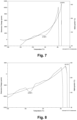
- Composition A had a glass transition temperature of -81.50 °C, and composition B of -94.96 °C.
- the results are shown in Figures 7 and 8 , respectively.
- a plunger side CCI test using CO 2 headspace analysis has been performed on glass syringes coated as described above with composition A and B and using a Datwyler FM257 stopper.
- the cooling rate has been ca. 1 °C/min.
- the headspace in the water filled samples has been 4 mm wherein the position of the headspace has been close to the stopper for the vertically oriented samples.
- Composition Filling medium Orientation Pass* (168 h, -80 °C) Pass* (1 month, -80 °C)
- Orientation Pass* (168 h, -80 °C) Pass* (1 month, -80 °C)
- Leakage values below 10 mbar CO 2 considered as pass.
- the stopper/barrel interface meets CCI at -80 °C.
- Composition Filling medium Orientation Pass (168 h, -80 °C) A 1,000 nm empty n/a 25/25 water horizontal 25/25 water vertical 25/25 B 1,400 nm empty n/a 25/25 water horizontal 25/25 water vertical 25/25
- the samples, controls, and sensors have been positioned in the plastic tub (or trays) including slots with temperature probes and slots with defect syringe controls. Similar sensors and controls are also used for horizontal samples.
- Set A has been measured at -80 °C with a headspace of 4 mm.
- Set B and set C have been measured at -96 °C with a headspace of 4 mm and 8 mm, respectively.
- the samples have been cooled at a cooling rate of 3 °C/min to 4 °C/min from -50 °C to -80 °C and held at that temperature for 15 min. With this preconditioning, in each set three runs of 30 samples, each, have been tested with different cooling rates from -80 °C to -96 °C.
- Set D has been a repetition of the runs with the highest cooling rate of sets B and C, this time with horizontal orientation of the syringes in trays.
- Set Temperature Headspace Orientation Cooling rate after preconditioning Pass A -80 °C 4 mm vertical 3 °C/min to 4 °C/min from -50 °C to -80 °C 30/30 -80 °C 4 mm vertical 4 °C/min to 6 °C/min from -50 °C to -80 °C 30/30 -80 °C 4 mm vertical 9 °C/min to 10 °C/min from -50 °C to -80 °C 25/30 -80 °C 4 mm vertical 15 °C/min to 20 °C/min from -50 °C to -80 °C 17/30 B -96 °C 4 mm vertical 0.5 °C/min to 1.5 °C/min from -80 °C to -96 °C 30/
Landscapes
- Health & Medical Sciences (AREA)
- Life Sciences & Earth Sciences (AREA)
- Engineering & Computer Science (AREA)
- Animal Behavior & Ethology (AREA)
- Veterinary Medicine (AREA)
- Public Health (AREA)
- General Health & Medical Sciences (AREA)
- Pharmacology & Pharmacy (AREA)
- Chemical & Material Sciences (AREA)
- Hematology (AREA)
- Heart & Thoracic Surgery (AREA)
- Vascular Medicine (AREA)
- Mechanical Engineering (AREA)
- Anesthesiology (AREA)
- Biomedical Technology (AREA)
- Organic Chemistry (AREA)
- Chemical Kinetics & Catalysis (AREA)
- General Chemical & Material Sciences (AREA)
- Geochemistry & Mineralogy (AREA)
- Materials Engineering (AREA)
- Epidemiology (AREA)
- Surgery (AREA)
- Dispersion Chemistry (AREA)
- Wood Science & Technology (AREA)
- Ceramic Engineering (AREA)
- Medical Preparation Storing Or Oral Administration Devices (AREA)
Priority Applications (4)
| Application Number | Priority Date | Filing Date | Title |
|---|---|---|---|
| EP23213401.5A EP4563543A1 (de) | 2023-11-30 | 2023-11-30 | Verfahren und glasbehälter zur lagerung einer pharmazeutischen zusammensetzung bei einer temperatur von -80 °c oder darunter |
| CN202411136958.3A CN120057400A (zh) | 2023-11-30 | 2024-08-19 | 在-80℃或更低温度下储存药物组合物的方法及玻璃容器 |
| US18/940,099 US20250177251A1 (en) | 2023-11-30 | 2024-11-07 | Method and glass container for storing a pharmaceutical composition at a temperature of -80 °C or below |
| KR1020240167201A KR20250083123A (ko) | 2023-11-30 | 2024-11-21 | 영하 80 ℃ 이하의 온도에서 약제 조성물을 저장하기 위한 방법 및 유리 용기 |
Applications Claiming Priority (1)
| Application Number | Priority Date | Filing Date | Title |
|---|---|---|---|
| EP23213401.5A EP4563543A1 (de) | 2023-11-30 | 2023-11-30 | Verfahren und glasbehälter zur lagerung einer pharmazeutischen zusammensetzung bei einer temperatur von -80 °c oder darunter |
Publications (1)
| Publication Number | Publication Date |
|---|---|
| EP4563543A1 true EP4563543A1 (de) | 2025-06-04 |
Family
ID=89030123
Family Applications (1)
| Application Number | Title | Priority Date | Filing Date |
|---|---|---|---|
| EP23213401.5A Pending EP4563543A1 (de) | 2023-11-30 | 2023-11-30 | Verfahren und glasbehälter zur lagerung einer pharmazeutischen zusammensetzung bei einer temperatur von -80 °c oder darunter |
Country Status (4)
| Country | Link |
|---|---|
| US (1) | US20250177251A1 (de) |
| EP (1) | EP4563543A1 (de) |
| KR (1) | KR20250083123A (de) |
| CN (1) | CN120057400A (de) |
Citations (6)
| Publication number | Priority date | Publication date | Assignee | Title |
|---|---|---|---|---|
| US6296893B2 (en) * | 1997-12-04 | 2001-10-02 | Schott Glass | Pharmaceutical packing device comprising a hollow plastic body having an improved internal lubricant layer and method of making same |
| EP3569272A1 (de) | 2018-05-14 | 2019-11-20 | SCHOTT Schweiz AG | Verschluss für einen behälter für pharmazeutische präparate und mit diesem verschluss versehener behälter |
| US20200078523A1 (en) * | 2018-09-10 | 2020-03-12 | Schott Ag | Packaging having sliding layer and method for pharmaceutical and cosmetic substances and preparation for producing same |
| WO2022200623A1 (en) * | 2021-03-25 | 2022-09-29 | Schott Ag | Pharmaceutical container |
| US20220315284A1 (en) * | 2021-03-25 | 2022-10-06 | Schott Ag | Coated glass element |
| WO2022207655A1 (en) * | 2021-03-30 | 2022-10-06 | Schott Schweiz Ag | System for low-temperature storage of a pharmaceutical composition, liquid composition, method and uses |
-
2023
- 2023-11-30 EP EP23213401.5A patent/EP4563543A1/de active Pending
-
2024
- 2024-08-19 CN CN202411136958.3A patent/CN120057400A/zh active Pending
- 2024-11-07 US US18/940,099 patent/US20250177251A1/en active Pending
- 2024-11-21 KR KR1020240167201A patent/KR20250083123A/ko active Pending
Patent Citations (6)
| Publication number | Priority date | Publication date | Assignee | Title |
|---|---|---|---|---|
| US6296893B2 (en) * | 1997-12-04 | 2001-10-02 | Schott Glass | Pharmaceutical packing device comprising a hollow plastic body having an improved internal lubricant layer and method of making same |
| EP3569272A1 (de) | 2018-05-14 | 2019-11-20 | SCHOTT Schweiz AG | Verschluss für einen behälter für pharmazeutische präparate und mit diesem verschluss versehener behälter |
| US20200078523A1 (en) * | 2018-09-10 | 2020-03-12 | Schott Ag | Packaging having sliding layer and method for pharmaceutical and cosmetic substances and preparation for producing same |
| WO2022200623A1 (en) * | 2021-03-25 | 2022-09-29 | Schott Ag | Pharmaceutical container |
| US20220315284A1 (en) * | 2021-03-25 | 2022-10-06 | Schott Ag | Coated glass element |
| WO2022207655A1 (en) * | 2021-03-30 | 2022-10-06 | Schott Schweiz Ag | System for low-temperature storage of a pharmaceutical composition, liquid composition, method and uses |
Non-Patent Citations (1)
| Title |
|---|
| HERGET CHRISTIAN: "An innovative solution to address silicone related concerns", 1 January 2016 (2016-01-01), XP055972925, Retrieved from the Internet <URL:https://www.ondrugdelivery.com/an-innovative-solution-to-address-siliconerelated-concerns/> [retrieved on 20221019] * |
Also Published As
| Publication number | Publication date |
|---|---|
| US20250177251A1 (en) | 2025-06-05 |
| CN120057400A (zh) | 2025-05-30 |
| KR20250083123A (ko) | 2025-06-09 |
Similar Documents
| Publication | Publication Date | Title |
|---|---|---|
| ES2373585T3 (es) | Miembros de sellado, artículos que usan los mismos y procedimientos de reducir fricción estática. | |
| US8802603B2 (en) | Medical components having coated surfaces exhibiting low friction and low reactivity | |
| CN101528281B (zh) | 具有显示出低摩擦的涂布表面的医疗组件和降低粘附的方法 | |
| US6482509B2 (en) | Coating system providing low friction | |
| US8075995B2 (en) | Coating system, articles and assembly using the same and methods of reducing sticktion | |
| EP3708205B1 (de) | Pharmazeutischer behälter und flüssige zusammensetzung | |
| EP1060030B1 (de) | Beschichtungssystem mit niedriger reibung | |
| EP4563543A1 (de) | Verfahren und glasbehälter zur lagerung einer pharmazeutischen zusammensetzung bei einer temperatur von -80 °c oder darunter | |
| EP4285963A1 (de) | Glasbehälter und verwendung einer beschichtung auf dem glasbehälter | |
| EP4649977A1 (de) | Verfahren zur herstellung eines beschichteten behälters |
Legal Events
| Date | Code | Title | Description |
|---|---|---|---|
| STAA | Information on the status of an ep patent application or granted ep patent |
Free format text: STATUS: EXAMINATION IS IN PROGRESS |
|
| PUAI | Public reference made under article 153(3) epc to a published international application that has entered the european phase |
Free format text: ORIGINAL CODE: 0009012 |
|
| 17P | Request for examination filed |
Effective date: 20231130 |
|
| AK | Designated contracting states |
Kind code of ref document: A1 Designated state(s): AL AT BE BG CH CY CZ DE DK EE ES FI FR GB GR HR HU IE IS IT LI LT LU LV MC ME MK MT NL NO PL PT RO RS SE SI SK SM TR |
|
| P01 | Opt-out of the competence of the unified patent court (upc) registered |
Free format text: CASE NUMBER: APP_31674/2025 Effective date: 20250701 |