EP4563759A1 - Hahn und duschvorrichtung - Google Patents
Hahn und duschvorrichtung Download PDFInfo
- Publication number
- EP4563759A1 EP4563759A1 EP24154363.6A EP24154363A EP4563759A1 EP 4563759 A1 EP4563759 A1 EP 4563759A1 EP 24154363 A EP24154363 A EP 24154363A EP 4563759 A1 EP4563759 A1 EP 4563759A1
- Authority
- EP
- European Patent Office
- Prior art keywords
- water channel
- opening
- channel body
- water
- housing
- Prior art date
- Legal status (The legal status is an assumption and is not a legal conclusion. Google has not performed a legal analysis and makes no representation as to the accuracy of the status listed.)
- Pending
Links
Images


Classifications
-
- E—FIXED CONSTRUCTIONS
- E03—WATER SUPPLY; SEWERAGE
- E03C—DOMESTIC PLUMBING INSTALLATIONS FOR FRESH WATER OR WASTE WATER; SINKS
- E03C1/00—Domestic plumbing installations for fresh water or waste water; Sinks
- E03C1/02—Plumbing installations for fresh water
- E03C1/04—Water-basin installations specially adapted to wash-basins or baths
- E03C1/042—Arrangements on taps for wash-basins or baths for connecting to the wall
Definitions
- the present disclosure relates to the technical field of bathroom products, in particular to a tap assembly, a faucet and a shower device.
- Many faucets such as a shower faucet, typically include a tap housing and a water channel body having a water channel and mounted within the tap housing.
- the tap housing can be made of metal, while the water channel body is usually made of plastic material.
- the water channel body made of plastic material is not only healthy and environmentally friendly, easy to form and manufacture, but also can be effective in heat insulation, preventing high-temperature hot water from transferring heat to the metal housing part.
- the water channel body is fixed to the tap housing by fasteners such as bolts, or when the water channel assembly is mounted within the tap housing, an additional limiting component is disposed between the water channel assembly and the tap housing to fix the water channel assembly within the tap housing by means of the additional limiting component.
- fasteners such as bolts
- an additional limiting component is disposed between the water channel assembly and the tap housing to fix the water channel assembly within the tap housing by means of the additional limiting component.
- Embodiments of the present disclosure provide a tap assembly, a faucet and a shower device, so as to solve the problems of low production efficiency and high production cost caused by complicated assembly between the tap housing and the water channel body, numerous parts, many assembly processes and the like.
- An embodiment of the present disclosure provides a tap assembly including a tap housing and a water channel body.
- the tap housing includes a housing body and a cover plate provided separately.
- An accommodating cavity is formed inside the housing body, and one side of the housing body is provided with a mounting opening communicated with the accommodating cavity.
- the cover plate is configured to be mounted at the mounting opening and connected with the housing body.
- a water channel is formed inside the water channel body, and the water channel body is provided with a water inlet port and a water outlet port communicated with the water channel, and the water channel body is configured to be mounted in the accommodating cavity. After the water channel body enters the accommodating cavity through the mounting opening, the cover plate is fitted with and mounted to the housing body to limit the water channel body at a mounting position in the accommodating cavity.
- the mounting opening and the water inlet port of the water channel body have the same orientation, and the cover plate is provided with a water inlet opening for corresponding to the water inlet port.
- a limiting protrusion is disposed on an inner side surface of the housing body, and the water channel body abuts against the limiting protrusion after entering the accommodating cavity to prevent the water channel body from continuing to move in an entry direction.
- the tap housing is provided with at least one opening
- the water channel body is provided with an opening fitting structure extendable into the opening
- the tap housing limits the opening fitting structure through the opening.
- the at least one opening includes a water inlet opening provided on the cover plate and corresponding to the water inlet port
- the opening fitting structure includes a water inlet connecting head provided on the water channel body and having the water inlet port.
- an inside of the cover plate facing the accommodating cavity is provided with a limiting part, and the limiting part is configured to limit the water inlet connecting head to restrict movement of the water inlet connecting head in a direction toward the outside of the mounting opening.
- the at least one opening includes a first end hole provided on the housing body
- the opening fitting structure includes a fitting end provided on the water channel body and extendable into the first end hole.
- the water channel body enters the accommodating cavity and abuts against the housing body and then moves towards the first end hole along a transverse direction, so that the fitting end can enter the first end hole.
- the transverse direction is a direction perpendicular to an entry direction of the water channel body into the accommodating cavity.
- the housing body is provided with a transverse limiting structure, and the water channel body enters the accommodating cavity and abuts against the housing body and then moves toward the transverse limiting structure along a transverse direction so as to be able to abut against the transverse limiting structure.
- the transverse direction is a direction perpendicular to an entry direction of the water channel body into the accommodating cavity.
- the cover plate is connected to the housing body in a clamping manner.
- the tap housing further includes a water outlet joint assembly configured to be connected with the water outlet port, the housing body is provided with a water outlet opening corresponding to the water outlet port, and the water outlet joint assembly has a fitting and mounting part fitted with the water outlet opening in size.
- the housing body includes an upper sidewall positioned above the water inlet port and a lower sidewall positioned below the water inlet port, the upper sidewall is configured to be mounted against a wall, and the lower sidewall is configured such that an assembly opening is formed between the lower sidewall and the wall when the upper sidewall abuts against the wall.
- An embodiment of the present disclosure also provides a faucet, which includes the tap assembly as described above.
- An embodiment of the present disclosure also provides a shower device, which includes a faucet as described above and a shower assembly which can be fitted with and mounted to the faucet.
- the water channel body is limited only by fitting itself with the tap housing, and no additional fixing components are adopted, for example, fasteners such as bolts are not adopted to fix the water channel body to the tap housing, or no additional limiting structures such as limiting rings are provided between the water channel body and the tap housing to fix the water channel body to the tap housing.
- the schemes provided by the embodiments of the present disclosure only need to enable the water channel body to enter the accommodating cavity of the housing body, and then fix the cover plate to the housing body to realize the limiting fixation of the water channel body in the tap housing, thus greatly reducing the number of assembled components, having the characteristics of simple assembly, few mounting procedures and the like, being beneficial to realizing the automatic production of tap products, and improving the production efficiency and saving the cost.
- 1-tap housing 11-housing body; 111-mounting opening; 112-upper water outlet opening; 113-lower water outlet opening; 114-first end hole; 115-second end hole; 116-limiting rib; 117-clamping groove; 118-upper sidewall; 119-lower sidewall; 120-end wall; 12-cover plate; 121-water inlet opening; 122-limiting part; 123-clamping part; 124-outer peripheral flange; 13-glass panel; 2-water channel body; 21-water inlet connecting head; 211-water inlet port; 212-positioning flange; 22-upper water outlet port; 23-lower water outlet port; 24-first connecting port; 25-second connecting port; 3-water inlet joint assembly; 4-upper water outlet joint assembly; 41-upper fitting and mounting part; 5-lower water outlet joint assembly; 51-lower fitting and mounting part; 6-switch assembly; 61-switch valve core; 62-first gland; 63-first decorative ring; 64-switch handle; 7-
- An embodiment of the present disclosure provides a tap assembly, as shown in FIG. 1 , including a tap housing 1 and a water channel body 2 mounted in the tap housing 1.
- the tap housing 1 may be a metal housing, which is easy to clean and improves aesthetics.
- the water channel body 2 may be made of a plastic material, which is healthy and environmentally friendly, easy to form and manufacture, and plays a role in heat insulation, avoiding heat transfer to the tap housing 1, thus having heat insulation and anti-scald effects.
- the tap housing 1 includes a housing body 11 and a cover plate 12 provided separately.
- An accommodating cavity is formed inside the housing body 11, and one side of the housing body 11 is provided with a mounting opening 111 communicated with the accommodating cavity.
- the cover plate 12 is configured to be mounted at the mounting opening 111 and connected with the housing body 11.
- a water channel is formed inside the water channel body 2, and the water channel body 2 is provided with a water inlet port 211 and a water outlet port communicated with the water channel.
- the water channel body 2 is configured to be mounted in the accommodating cavity.
- the cover plate 12 is fitted with and mounted to the housing body 11 to limit the water channel body 2 at a mounting position in the accommodating cavity.
- a back side (not shown in FIG. 1 ) of the housing body 11 has a mounting opening 111.
- the water channel body 2 can be moved along the arrow direction to the mounting opening 111, enter the accommodating cavity of the housing body 11 through the mounting opening 111 and reach the mounting position. Then, the cover plate 12 is mounted to the housing body 11 to realize the limiting of the water channel body 2 in the tap housing 1.
- the water channel body 2 is limited only by fitting itself with the tap housing 1, and no additional fixing components are adopted, for example, fasteners such as bolts are not adopted to fix the water channel body to the tap housing, or no additional limiting structures such as limiting rings are provided between the water channel body and the tap housing to fix the water channel body to the tap housing.
- the embodiments of the present disclosure only need to enable the water channel body 2 to enter the accommodating cavity of the housing body 11, and then fix the cover plate 12 to the housing body 11 to realize the limiting fixation of the water channel body 2 in the tap housing 1. It greatly reduces the number of assembled components and has the characteristics of simple assembly, few mounting procedures and the like, which are beneficial to realizing the automatic production of tap products, improving the production efficiency and saving the cost.
- the housing body 11 is configured such that the mounting opening 111 and the water inlet port 211 of the water channel body 2 have the same orientation, and the cover plate 12 is provided with a water inlet opening 121 corresponding to the water inlet port 211. That is, when the tap assembly in this embodiment is used for a faucet, the cover plate 12 is located at the back side of the faucet having the water inlet port 211, and the cover plate 12 is disposed at the back side, so that the cover plate 12 can be shielded when the faucet is mounted on a wall or other structure, which is beneficial to improving the aesthetics of the faucet.
- the tap assembly provided by the embodiments of the present disclosure is suitable for the shower faucet of the bathroom.
- a positional relationship between the water channel body 2 and the tap housing 1 described in the present disclosure refers to a positional relationship between the water channel body 2 and the tap housing 1 when the water channel body 2 is mounted to the tap housing 1.
- the inner side surface of the housing body 11 is provided with a limiting protrusion, and the water channel body 2 abuts against the limiting protrusion after entering the accommodating cavity to restrict the water channel body 2 from continuing to move in an entry direction.
- the limiting protrusion may be a plurality of limiting ribs 116 provided on the inner side surface of the housing body 11, or other types of structures such as abutment blocks or the like.
- the tap housing 1 is provided with at least one opening
- the water channel body 2 is provided with an opening fitting structure extendable into the opening.
- the tap housing 1 limits the opening fitting structure through the opening.
- the at least one opening includes a water inlet opening 121 provided on the cover plate 12 and corresponding to the water inlet port 211 of the water channel body 2, and the opening fitting structure includes a water inlet connecting head 21 provided on the water channel body 2 and having the water inlet port 211.
- the cover plate 12 is mounted to the tap housing 1
- the water inlet connecting head 21 extends into the water inlet opening 121
- the cover plate 12 limits the water inlet connecting head 21 in the circumferential direction through the water inlet opening 121.
- the circumferential limiting of the water inlet connecting head 21 by the water inlet opening 121 enables the limiting on the water channel body 2 in a plurality of directions substantially perpendicular to the entry direction entering the accommodating cavity.
- a limiting part 122 is provided on a side of the cover plate 12 facing the accommodating cavity.
- the limiting part 122 is configured to limit the water inlet connecting head 21 so as to limit the movement of the water inlet connecting head 21 in a direction toward the outside of the mounting opening 111, thereby realizing the limiting on the water channel body 2 in this direction.
- the limiting part 122 may be an annular limiting structure around the water inlet opening 121, and a positioning flange 212 is provided on the outer circumferential surface of the water inlet connecting head 21. After the cover plate 12 is mounted, the limiting part 122 is positioned outside the positioning flange 212 for limiting.
- FIG. 6 illustrates a state in which the water inlet connecting head 21 of the water channel body 2 extends into the water inlet opening 121 of the cover plate 12 and the limiting part 122 on the cover plate 12 is fitted with the positioning flange 212 on the outer circumferential surface of the water inlet connecting head 21 after the cover plate 12 is mounted to the housing body 11, thereby preventing the water inlet connecting head 21 from moving in the direction toward the outside of the mounting opening 111 by the limiting part 122.
- the at least one opening may include a first end hole 114 provided on the housing body 11, and the opening fitting structure includes a fitting end provided on the water channel body 2 and extendable into the first end hole 114.
- the water channel body 2 moves towards the first end hole 114 along a transverse direction, so that the fitting end can enter the first end hole 114.
- the transverse direction is a direction perpendicular to the entry direction of the water channel body 2 into the accommodating cavity.
- the fitting end of the water channel body 2 fitted with the first end hole 114 may be a first connecting port 24 of the water channel body 2 for connecting the switch assembly 6, or a second connecting port 25 for connecting the temperature control assembly 7, or another positioning port.
- the water channel body 2 moves to the fitting end along the transverse direction and enters the first end hole 114.
- the water channel body 2 can be positioned in various directions perpendicular to the transverse direction.
- the transverse direction is a left-right direction when viewed from the entry direction. In other embodiments, the transverse direction may be an up-down direction.
- the housing body 11 is provided with a transverse limiting structure. After the water channel body 2 enters the accommodating cavity and abuts against the housing body 11, the water channel body 2 moves towards the transverse limiting structure along the transverse direction and can abut against the transverse limiting structure.
- the transverse limiting structure limits the water channel body 2 to prevent it from continuing to move in the transverse direction.
- the transverse direction is a direction perpendicular to the entry direction along which the water channel body 2 enters the accommodating cavity.
- the transverse limiting structure may be a circumferential edge of the housing body 11 around the first end hole 114, and an annular recessed structure is provided on the outer circumference of the end face of the fitting end of the water channel body 2 to form a step shape. Referring to the structure of the first connecting port 24 fitted with the first end hole 114 illustrated in FIG. 5 , the annular recessed structure of the first connecting port 24 abuts against the circumferential edge of the first end hole 114 for limiting after the first connecting port 24 is inserted into the first end hole 114.
- the water channel body 2 abuts against the housing body 11 in the entry direction along which the water channel body 2 enters the accommodating cavity, and then moves transversely until the fitting end is inserted into the first end hole 114. After the first end hole 114 limits the fitting end in the transverse direction, the water channel body 2 reaches the mounting position. At this time, the water channel body 2 has the degree of freedom only in the transverse direction facing away from the first end hole 114.
- the cover plate 12 When the cover plate 12 is mounted to the mounting opening 111 of the housing body 11, the cover plate 12 can be fitted with the water channel body 2 at a predetermined fitting position, thereby realizing rapid mounting of the cover plate 12.
- the cover plate 12 is mounted at the mounting opening 111 so that the water inlet opening 121 is correctly aligned and fitted with the water inlet connecting head 21 on the water channel body 2 to facilitate rapid mounting of the cover plate 12 and complete positioning of the water channel body 2 through the cover plate 12.
- the water channel body 2 may be limited in the transverse direction by directly using the housing wall of the housing body 11 as a transverse limiting structure without inserting the fitting end into the first end hole 114. Specifically, after the water channel body 2 moves into the accommodating cavity along the entry direction and then moves in the transverse direction perpendicular to the entry direction to abut against the transverse limiting structure, the water channel body 2 is in the mounting position. When the cover plate 12 is mounted, the cover plate 12 can also be correctly fitted with the water channel body 2, and the complete limiting of the water channel body 2 in the tap housing 1 can be realized through the mounting of the cover plate 12.
- the cover plate 12 is connected to the housing body 11 by clamping.
- the housing body 11 is provided with a clamping groove 117
- the cover plate 12 is provided with a clamping part 123 for fitting and clamping with the clamping groove 117.
- the cover plate 12 is fixed to the housing body 11.
- the cover plate 12 can support the housing body 11 and avoid deformation of the housing body 11.
- the clamping groove may be provided on the cover plate 12, and the clamping part 123 may be provided on the housing body 11.
- the outer periphery of the cover plate 12 may be provided with an outer peripheral flange 124 configured to be fitted with an inner wall surface of the housing body 11 surrounding the mounting opening 111.
- the outer peripheral flange 124 of the cover plate 12 moves along the inner wall surface of the housing body 11 until the clamping part 123 is clamped with the clamping groove 117.
- the outer peripheral flange 124 is fitted with the inner wall surface of the housing body 11 surrounding the mounting opening 111, which has a guiding effect and ensures that the cover plate 12 is not inclined.
- the outer peripheral flange 124 can increase the contact area between the cover plate 12 and the inner wall surface, thus having a better supporting effect on the housing body 11.
- connection mode between the cover plate 12 and the housing body 11 is not limited, which may be a clamped or bolted connection mode.
- the mounting process of the tap assembly is described below according to the embodiments shown in FIGS. 3-7 .
- the water channel body 2 moves along the direction of an arrow toward the mounting opening 111 of the housing body 11 and into the accommodating cavity.
- the water channel body 2 abuts against the limiting ribs 116 of the housing body 11, and then moves in the transverse direction indicated by the arrow until the first connecting port 24 of the water channel body 2 extends into the first end hole 114 of the housing body 11, and the step-shaped mounting structure of the first connecting port 24 abuts against the circumferential edge of the housing body 11 surrounding the first end hole 114, thereby limiting the water channel body 2 in the transverse direction towards the first end hole 114 and in various directions perpendicular to the transverse direction. At this time, the water channel body 2 is in the mounting position.
- the cover plate 12 is fixed to the housing body 11.
- the water inlet connecting head 21 of the water channel body 2 is inserted into the water inlet opening 121 of the cover plate 12, and the limiting part 122 on the cover plate 12 limits the positioning flange 212 on the water inlet connecting head 21, thereby realizing the mounting of the water channel body 2 in the tap housing 1 through the fitting between the cover plate 12 and the housing body 11.
- a water inlet joint assembly 3 is mounted on the water inlet connecting head 21.
- the water inlet joint assembly 3 may be mounted after the cover plate 12 is mounted to the housing body 11.
- the water inlet joint assembly 3 may be mounted to the water inlet connecting head 21 and then the cover plate 12 is mounted.
- an upper water outlet joint assembly 4 is mounted at the upper water outlet port 22 of the water channel body, and a lower water outlet joint assembly 5 is mounted at the lower water outlet port 23 of the water channel body.
- limiting and fixing of the water channel body 2 through the fitting between the housing body 11 and the cover plate 12 are not limited to the embodiments described above, other ways can be used to limit the water channel body 2.
- a mounting opening is provided on the upper side of the housing body 11
- a water outlet opening is provided on the lower side of the housing body 11
- the water channel body 2 is provided with a downward water outlet connecting head.
- the water outlet connecting head is fitted with the water outlet opening provided at the bottom of the housing body 11 for positioning after the water channel body 2 enters the accommodating cavity from the mounting opening of the housing body 11.
- a port for positioning the water channel body 2 in a transverse direction perpendicular to the water inlet direction of the water channel body 2 is provided, so as to position the water channel body 2 in the transverse direction in the mounting position.
- the cover plate 12 is fitted with the housing body 11 when the cover plate 12 covers the mounting opening 111, to realize the mounting of the water channel body 2 in the tap housing 1.
- the faucet further includes a water inlet joint assembly 3 and a water outlet joint assembly, both of which are mounted by threads.
- the water inlet connecting head 21 having the water inlet port 211 of the water channel body 2 has internal threads, and the water inlet joint assembly 3 is connected to the water inlet port of the water channel body 2 by threads.
- the water channel body 2 has two water outlet ports, i.e., an upper water outlet port 22 located at the upper part of the water channel body 2 and a lower water outlet port 23 located at the lower part of the water channel body 2.
- the upper water outlet port 22 and the lower water outlet port 23 of the water channel body 2 also have internal threads respectively.
- the upper water outlet joint assembly 4 is connected to the upper water outlet port 22 by threads
- the lower water outlet joint assembly 5 is connected to the lower water outlet port 23 by threads.
- the water inlet joint assembly 3 and the water outlet joint assemblies are generally connected to the water channel body 2 after the cover plate 12 is fixed to the housing body 11.
- each joint assembly can be aligned with the corresponding water inlet port or water outlet port, so the water inlet joint assembly 3 and/or the water outlet joint assemblies can also be connected to the water channel body 2 before the cover plate 12 is mounted.
- the tap assembly includes a water outlet joint assembly configured to be connected with the water outlet port of the water channel body 2.
- a water outlet opening corresponding to the water outlet port is provided on the housing body 11, and the water outlet joint assembly is provided with a fitting and mounting part fitted with the water outlet opening in size.
- the fitting and mounting part is fitted with the water outlet opening of the housing body 11, so that the water outlet opening of the housing body 11 limits the water outlet joint assembly.
- the water channel body 2 is provided with an upper water outlet port 22 and a lower water outlet port 23.
- the housing body 11 has an upper water outlet opening 112 corresponding to the upper water outlet port 22 and a lower water outlet opening 113 corresponding to the lower water outlet port 23.
- the upper water outlet joint assembly 4 is connected to the upper water outlet port 22 through the upper water outlet opening 112, and the lower water outlet joint assembly 5 is connected to the lower water outlet port 23 through the lower water outlet opening 113.
- the upper water outlet joint assembly 4 has an upper fitting and mounting part 41. When the upper water outlet joint assembly 4 is connected to the upper water outlet port 22, the upper fitting and mounting part 41 is fitted with and mounted in the upper water outlet opening 112.
- the upper water outlet joint assembly 4 is positioned on the housing body 11 in the circumferential direction through the fitting between the upper fitting and mounting part 41 and the upper water outlet opening 112.
- the lower water outlet joint assembly 5 has a lower fitting and mounting part 51.
- the lower fitting and mounting part 51 is fitted with and mounted in the lower water outlet opening 113 of the housing body 11.
- the lower water outlet joint assembly 5 is positioned on the housing body 11 in the circumferential direction through the fitting between the lower fitting and mounting part 51 and the lower water outlet opening 113. Since the upper water outlet joint assembly 4 and the lower water outlet joint assembly 5 are positioned on the housing body 11 and connected to the water channel body 2, the water channel body 2 can be further securely positioned in the tap housing 1.
- the housing body 11 includes an upper sidewall 118 positioned above the water inlet port 211, and a lower sidewall 119 positioned below the water inlet port 211.
- the upper sidewall 118 is configured to be mounted against a wall
- the lower sidewall 119 is configured such that an assembly opening 20 is formed between the lower sidewall 119 and the wall when the upper sidewall 118 abuts against the wall.
- the housing body 11 also includes end walls 120 at both ends and connecting the upper sidewall 118 and the lower sidewall 119, respectively.
- the end walls 120 are also configured to extend and flush with the upper sidewall 118 so as to be mounted against the wall.
- the end walls 120 can shield the structure inside the housing body 11 from both ends.
- FIGS. 11-13 schematically illustrate the mounting process of the faucet against the wall by adopting the housing body 11 according to an embodiment of the present disclosure.
- the faucet When the faucet is connected with a bent joint 8 on a wall 9, the upper sidewall 118 and the end walls 120 of the tap housing 1 abut against the wall 9, which can shield the connection structure between the water inlet port 211 of the water channel body 2 and the bent joint 8 from above and both ends, while the assembly opening 20 is formed between the lower sidewall 119 and the wall 9.
- the lower assembly opening 20 it is convenient to disassemble and assemble the water inlet joint assembly 3 on the water inlet port 211 from and with the bent joint 8 on the wall 9, so as to facilitate maintenance and replacement of the faucet.
- customers replace a new tap product the faucet is disassembled through the assembly opening 20, and the bent joint 8 on the wall 9 is retained. The new tap product is reconnected to the retained bent joint 8 through the water inlet joint assembly to complete the rapid replacement of the new product.
- a faucet which includes the tap assembly as described above.
- the faucet further includes a switch assembly 6 and a temperature control assembly 7.
- the water channel body 2 is provided with a first connecting port 24 and a second connecting port 25.
- the first connecting port 24 and the second connecting port 25 can be respectively provided with connection threads.
- the tap housing 1 is provided with a first end hole 114 corresponding to the first connecting port 24 and a second end hole 115 corresponding to the second connecting port 25.
- the switch assembly 6 includes a switch valve core 61 and a switch handle 64.
- the switch valve core 61 is inserted into the first connecting port 24 of the water channel body 2 through the first end hole 114 of the tap housing, and the switch handle 64 is connected to the switch valve core 61 to control the switch valve core 61.
- the switch assembly 6 also includes a first gland 62 for locking the switch valve core 61 to the first connecting port 24.
- the first gland 62 can be connected to the first connecting port 24 by threads so as to lock the switch valve core 61 within the first connecting port 24.
- a first decorative ring 63 can also be provided between the first gland 62 and the switch handle 64.
- the temperature control assembly 7 includes a temperature control valve core 71 and a temperature control handle 74.
- the temperature control valve core 71 is inserted into the second connecting port 25 of the water channel body through the second end hole 115 of the tap housing, and the temperature control handle 74 is connected with the temperature control valve core 71 to control the temperature control valve core 71.
- the temperature control assembly 7 also includes a second gland 72 for locking the temperature control valve core 71 to the second connecting port 25.
- the second gland 72 can be connected to the second connecting port 25 by threads so as to lock the temperature control valve core 71 within the second connecting port 25.
- a second decorative ring 73 can also be provided between the second gland 72 and the temperature control handle 74.
- the temperature control assembly 7 controls the water inlet of the two water inlet ports 211 to adjust the temperature of the mixed water, and the switch assembly 6 controls the flow rate and the switch of the water flow, which are common technical means for those skilled in the art, and their working principles will not be repeated here.
- the faucet provided by the embodiments of the present disclosure can be provided with different types of tap housings 1 fitted with the water channel body 2. Different tap housings 1 can be replaced according to different use requirements.
- the faucet provided by the embodiments of the present disclosure is usually a shower faucet used in a bathroom.
- the faucet has a tap housing mounted against a wall, the upper sidewall 118 and the end walls 120 of the tap housing are mounted against the wall 9.
- an assembly opening 20 is formed between the lower sidewall 119 of the tap housing and the wall to mount the faucet through the assembly opening.
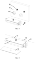
- FIGS. 14-15 show that the faucet has a tap housing which is not mounted against the wall. Since the tap housing is not mounted against the wall, in order to avoid exposing the connection structure between the water inlet joint assembly and the bent joint 8 on the wall and affecting the aesthetics, a decorative cover 10 can be provided at the connection position. In addition, a glass panel 13 or a silicone panel lamp can be provided on the housing according to customer requirements to increase product characteristics.
- a shower device which includes a faucet as described above and a shower assembly capable of being fitted and connected with the faucet.
- orientation or position relationships indicated by the terms “upper”, “lower”, “one side”, “the other side”, “one end”, “the other end”, “side”, “relative”, “corners”, “periphery”, “square structure” and the like are based on the orientation or position relationships shown in the drawings, which are only for convenience of describing the present disclosure and simplifying the description, rather than indicating or implying that the structure referred has the specific orientation, or is constructed and operated in the specific orientation, and thus cannot be interpreted as a limitation on the present disclosure.
- connection In the description of the embodiments of the present disclosure, unless otherwise explicitly specified and limited, the terms “connection”, “direct connection”, “indirect connection”, “fixed connection”, “mounting” and “assembly” should be understood in a broad sense. For example, they may be fixed connection, detachable connection or integrated connection; and the terms “mounting”, “connection” and “fixed connection” may be direct connection, or indirect connection through an intermediary, or may be an internal communication between two elements.
- connection direct connection
- indirect connection In the description of the embodiments of the present disclosure, unless otherwise explicitly specified and limited, the terms “connection”, “direct connection”, “indirect connection”, “fixed connection”, “mounting” and “assembly” should be understood in a broad sense. For example, they may be fixed connection, detachable connection or integrated connection; and the terms “mounting”, “connection” and “fixed connection” may be direct connection, or indirect connection through an intermediary, or may be an internal communication between two elements.
Landscapes
- Health & Medical Sciences (AREA)
- Life Sciences & Earth Sciences (AREA)
- Engineering & Computer Science (AREA)
- Hydrology & Water Resources (AREA)
- Public Health (AREA)
- Water Supply & Treatment (AREA)
- Domestic Plumbing Installations (AREA)
Applications Claiming Priority (1)
| Application Number | Priority Date | Filing Date | Title |
|---|---|---|---|
| CN202323292947.8U CN221504093U (zh) | 2023-12-01 | 2023-12-01 | 一种龙头组件、水龙头及淋浴装置 |
Publications (1)
| Publication Number | Publication Date |
|---|---|
| EP4563759A1 true EP4563759A1 (de) | 2025-06-04 |
Family
ID=89766978
Family Applications (1)
| Application Number | Title | Priority Date | Filing Date |
|---|---|---|---|
| EP24154363.6A Pending EP4563759A1 (de) | 2023-12-01 | 2024-01-29 | Hahn und duschvorrichtung |
Country Status (2)
| Country | Link |
|---|---|
| EP (1) | EP4563759A1 (de) |
| CN (1) | CN221504093U (de) |
Citations (3)
| Publication number | Priority date | Publication date | Assignee | Title |
|---|---|---|---|---|
| EP2241685A2 (de) * | 2009-04-08 | 2010-10-20 | Ostnor AB | Sanitärarmatur |
| EP3444405B1 (de) * | 2017-08-16 | 2020-10-07 | Xiamen Lota International Co., Ltd. | Thermostatarmatur |
| EP3913152A1 (de) * | 2020-05-22 | 2021-11-24 | Fujian Xihe Sanitary Ware Technology Co., Ltd. | Wandmontierte wasserausstossvorrichtung |
-
2023
- 2023-12-01 CN CN202323292947.8U patent/CN221504093U/zh active Active
-
2024
- 2024-01-29 EP EP24154363.6A patent/EP4563759A1/de active Pending
Patent Citations (3)
| Publication number | Priority date | Publication date | Assignee | Title |
|---|---|---|---|---|
| EP2241685A2 (de) * | 2009-04-08 | 2010-10-20 | Ostnor AB | Sanitärarmatur |
| EP3444405B1 (de) * | 2017-08-16 | 2020-10-07 | Xiamen Lota International Co., Ltd. | Thermostatarmatur |
| EP3913152A1 (de) * | 2020-05-22 | 2021-11-24 | Fujian Xihe Sanitary Ware Technology Co., Ltd. | Wandmontierte wasserausstossvorrichtung |
Also Published As
| Publication number | Publication date |
|---|---|
| CN221504093U (zh) | 2024-08-09 |
Similar Documents
| Publication | Publication Date | Title |
|---|---|---|
| RU2403483C2 (ru) | Узел клапана | |
| US10184575B2 (en) | Faucet with multi-directional controls | |
| US8461705B2 (en) | Faucet hydroelectric generator | |
| WO2019085530A1 (zh) | 冰箱制冰机的进水组件及冰箱 | |
| US10935157B2 (en) | Low profile faucet handle assembly for a roman tub | |
| EP3444406B1 (de) | Thermostatarmatur zum abstellen von artikeln | |
| KR101237984B1 (ko) | 벽면 배관에 대한 수전 연결구 | |
| US11821183B2 (en) | Fast assembling faucet component for dual water sources | |
| WO2023020401A1 (zh) | 车身地板总成和具有其的车辆 | |
| CN221504093U (zh) | 一种龙头组件、水龙头及淋浴装置 | |
| CN204852473U (zh) | 多功能不锈钢恒温龙头本体结构 | |
| CN108814513B (zh) | 喷臂组件和洗涤电器 | |
| CN212408870U (zh) | 柜式空调器 | |
| US20260139751A1 (en) | Faucet and installation structure of valve seat thereof | |
| TWM645913U (zh) | 恆溫閥組及其閥總成 | |
| CN221347217U (zh) | 用于水泵的控制阀 | |
| CN210964225U (zh) | 净水机 | |
| US20250353724A1 (en) | Water dispenser | |
| CN216782375U (zh) | 电机壳模具上模环形冷却装置 | |
| CN216382694U (zh) | 一种抽取式龙头的本体结构和抽取式龙头 | |
| CN218846402U (zh) | 一种面板组件及空气调节设备 | |
| CN216567901U (zh) | 一种全智能多功能自动化喷雾机 | |
| CN223359246U (zh) | 气缸套及具有其的发动机 | |
| CN217653291U (zh) | 一种水力发电淋浴器 | |
| CN212080300U (zh) | 一种用于水龙头的锁紧结构以及水龙头 |
Legal Events
| Date | Code | Title | Description |
|---|---|---|---|
| PUAI | Public reference made under article 153(3) epc to a published international application that has entered the european phase |
Free format text: ORIGINAL CODE: 0009012 |
|
| STAA | Information on the status of an ep patent application or granted ep patent |
Free format text: STATUS: REQUEST FOR EXAMINATION WAS MADE |
|
| 17P | Request for examination filed |
Effective date: 20240129 |
|
| AK | Designated contracting states |
Kind code of ref document: A1 Designated state(s): AL AT BE BG CH CY CZ DE DK EE ES FI FR GB GR HR HU IE IS IT LI LT LU LV MC ME MK MT NL NO PL PT RO RS SE SI SK SM TR |