EP4563761A1 - Système de toilettes suspendu au mur - Google Patents
Système de toilettes suspendu au mur Download PDFInfo
- Publication number
- EP4563761A1 EP4563761A1 EP22960677.7A EP22960677A EP4563761A1 EP 4563761 A1 EP4563761 A1 EP 4563761A1 EP 22960677 A EP22960677 A EP 22960677A EP 4563761 A1 EP4563761 A1 EP 4563761A1
- Authority
- EP
- European Patent Office
- Prior art keywords
- wall
- discharge pipe
- sewage
- pipe
- outlet
- Prior art date
- Legal status (The legal status is an assumption and is not a legal conclusion. Google has not performed a legal analysis and makes no representation as to the accuracy of the status listed.)
- Withdrawn
Links
Images


Classifications
-
- E—FIXED CONSTRUCTIONS
- E03—WATER SUPPLY; SEWERAGE
- E03D—WATER-CLOSETS OR URINALS WITH FLUSHING DEVICES; FLUSHING VALVES THEREFOR
- E03D11/00—Other component parts of water-closets, e.g. noise-reducing means in the flushing system, flushing pipes mounted in the bowl, seals for the bowl outlet, devices preventing overflow of the bowl contents; devices forming a water seal in the bowl after flushing, devices eliminating obstructions in the bowl outlet or preventing backflow of water and excrements from the waterpipe
- E03D11/13—Parts or details of bowls; Special adaptations of pipe joints or couplings for use with bowls, e.g. provisions in bowl construction preventing backflow of waste-water from the bowl in the flushing pipe or cistern, provisions for a secondary flushing, for noise-reducing
- E03D11/14—Means for connecting the bowl to the wall, e.g. to a wall outlet
- E03D11/143—Mounting frames for toilets and urinals
-
- E—FIXED CONSTRUCTIONS
- E03—WATER SUPPLY; SEWERAGE
- E03D—WATER-CLOSETS OR URINALS WITH FLUSHING DEVICES; FLUSHING VALVES THEREFOR
- E03D11/00—Other component parts of water-closets, e.g. noise-reducing means in the flushing system, flushing pipes mounted in the bowl, seals for the bowl outlet, devices preventing overflow of the bowl contents; devices forming a water seal in the bowl after flushing, devices eliminating obstructions in the bowl outlet or preventing backflow of water and excrements from the waterpipe
- E03D11/02—Water-closet bowls ; Bowls with a double odour seal optionally with provisions for a good siphonic action; siphons as part of the bowl
- E03D11/10—Bowls with closure elements provided between bottom or outlet and the outlet pipe; Bowls with pivotally supported inserts
-
- E—FIXED CONSTRUCTIONS
- E03—WATER SUPPLY; SEWERAGE
- E03D—WATER-CLOSETS OR URINALS WITH FLUSHING DEVICES; FLUSHING VALVES THEREFOR
- E03D11/00—Other component parts of water-closets, e.g. noise-reducing means in the flushing system, flushing pipes mounted in the bowl, seals for the bowl outlet, devices preventing overflow of the bowl contents; devices forming a water seal in the bowl after flushing, devices eliminating obstructions in the bowl outlet or preventing backflow of water and excrements from the waterpipe
- E03D11/13—Parts or details of bowls; Special adaptations of pipe joints or couplings for use with bowls, e.g. provisions in bowl construction preventing backflow of waste-water from the bowl in the flushing pipe or cistern, provisions for a secondary flushing, for noise-reducing
- E03D11/16—Means for connecting the bowl to the floor, e.g. to a floor outlet
-
- E—FIXED CONSTRUCTIONS
- E03—WATER SUPPLY; SEWERAGE
- E03D—WATER-CLOSETS OR URINALS WITH FLUSHING DEVICES; FLUSHING VALVES THEREFOR
- E03D11/00—Other component parts of water-closets, e.g. noise-reducing means in the flushing system, flushing pipes mounted in the bowl, seals for the bowl outlet, devices preventing overflow of the bowl contents; devices forming a water seal in the bowl after flushing, devices eliminating obstructions in the bowl outlet or preventing backflow of water and excrements from the waterpipe
- E03D11/18—Siphons
Definitions
- the present application relates to, but is not limited to, the field of bathroom equipment, and in particular to a wall-mounted toilet system.
- Wall-mounted toilets usually need to be mounted by chiseling a wall or building a wall.
- the installation is troublesome and laborious. Chiseling or building walls will increase the construction period to varying degrees, and the installation operation requires relatively high skills of the mounting master.
- some wall-mounted toilets have external racks and the wall digging is not needed.
- the sewage discharge pipeline needs to enter the wall, resulting in the need to still dig the wall during the overall installation process of the wall-mounted toilet, which is troublesome and laborious, and the installation cycle is long.
- An embodiment of the present application provides a wall-mounted toilet system.
- the wall-mounted toilet system includes a toilet body, a sewage discharge pipe group, and a wall-mounted bracket.
- the wall-mounted bracket is configured to be fixedly connected with a wall body, and the toilet body is fixed to the wall-mounted bracket.
- the toilet body is provided with a sewage outlet.
- the sewage discharge pipe group is provided outside the wall body and is configured to communicate the sewage outlet with a ground sewage discharge pipeline.
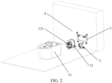
- FIGS. 1 to 6 An embodiment of the present application provides a wall-mounted toilet system, as shown in FIGS. 1 to 6 .
- the wall-mounted toilet system includes a toilet body 1, a sewage discharge pipe group 2, and a wall-mounted bracket 3.
- the wall-mounted bracket 3 is configured to be fixedly connected with a wall body 4, and the toilet body 1 is fixed to the wall-mounted bracket 3.
- the toilet body 1 is provided with a sewage outlet 122.
- the sewage discharge pipe group 2 is disposed outside the wall body 4, and is configured to communicate the sewage outlet 122 with a ground sewage discharge pipeline 5.
- the wall-mounted bracket 3 plays a role of fixedly mounting the toilet body 1, the wall-mounted bracket 3 is fixedly mounted at a set position of the wall body 4, and a toilet seat body 11 is fixedly mounted on the wall-mounted bracket 3.
- the wall-mounted bracket 3 is externally installed and is mounted on a cavity body through expansion bolts and other components. There is no need to chisel or build a wall for the mounting, which saves time and labor, and has relatively low skill requirements for a mounting master, thereby facilitating the reduction of mounting costs.
- the toilet body 1 and the wall-mounted bracket 3 can be connected by bolts or the like.
- the sewage outlet 122 of the toilet body 1 is in communication with the ground sewage discharge pipeline 5 on the ground through the sewage discharge pipe group 2, so as to realize the ground discharge mode of the wall-mounted toilet, so that it is not needed to chisel a wall or build a wall during the installation process of the wall-mounted toilet system, which is convenient for installation.
- the sewage discharge pipe group 2 is externally mounted, which is convenient and quick to repair when failure occurs during subsequent use.
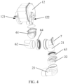
- the sewage discharge pipe group 2 includes a rear discharge pipe 21, an adjustment pipe 22, and a ground discharge pipe joint 23 which are communicated in sequence.
- An inlet of the rear discharge pipe 21 is in communication with the sewage outlet 122, and an outlet of the ground discharge pipe joint 23 is in communication with the ground sewage discharge pipeline 5.
- the inlet of the rear discharge pipe 21 is in communication with the sewage outlet 122 of the toilet body 1, and an outlet of the rear discharge pipe 21 is in communication with an inlet of the adjustment pipe 22.
- the outlet of the adjustment pipe 22 is in communication with an inlet of the ground discharge pipe joint 23, and the outlet of the ground discharge pipe joint 23 is in communication with the ground sewage discharge pipeline 5, so that the toilet body 1 is communicated to the ground sewage discharge pipeline 5.
- the rear discharge pipe 21 extends rearward after being in communication with the toilet body 1, and extends to a position above the ground discharge pipe joint 23.
- the adjustment pipe 22 is used for adjusting the connection position, so that when the rear discharge pipe 21 is not positioned directly above the ground discharge pipe joint 23, the rear discharge pipe 21 can still be communicated through the adjustment pipe 22.
- the inlet of the ground discharge pipe joint 23 extends out of the ground, and the other end of the ground discharge pipe joint 23 extends into the ground to communicate with the ground sewage discharge pipeline 5.
- the rear discharge pipe 21 is an elbow pipe, the inlet of the rear discharge pipe 21 is provided forward, and the outlet of the rear discharge pipe 21 is provided downward.
- the inlet of the rear discharge pipe 21 is provided forward so as to communicate with the sewage outlet 122 of the toilet body 1.
- the outlet of the rear discharge pipe 21 is provided downward so as to communicate with the adjustment pipe 22, thereby discharging sewage into the ground sewage discharge pipeline 5.
- the rear discharge pipe 21 in the form of an elbow pipe facilitates the provision of a connecting structure at the bend to be connected and fixed with the wall-mounted bracket 3.
- the rear discharge pipe 21 may be provided with a transitional fillet at the bend to prevent sewage from accumulating at the bend.
- the inlet of the adjustment pipe 22 is provided upward, the outlet of the adjustment pipe 22 is provided downward, and a central axis of the outlet of the adjustment pipe 22 is positioned on a front side of a central axis of the inlet of the adjustment pipe 22.
- the inlet of the adjustment pipe 22 is provided upward so as to communicate with the outlet of the rear discharge pipe 21.
- the outlet of the adjustment pipe 22 is provided downward so as to communicate with the ground sewage discharge pipeline 5.
- the adjustment pipe 22 is used to adjust the mounting position of the rear discharge pipe 21.
- the central axis of the outlet of the adjustment pipe 22 is positioned on the front side of the central axis of the inlet of the adjustment pipe 22.
- the adjustment pipe 22 includes an outlet section positioned relatively forward and an inlet section positioned relatively rearward.
- the inlet section positioned relatively rearward is in communication with the outlet of the rear discharge pipe 21, and the outlet section positioned relatively forward extends the outlet of the adjustment pipe 22 forward so as to align with the ground discharge pipe joint 23 on the ground, which makes full use of the space at the rear of the toilet body 1, and avoids interference between pipes within the rear of the toilet and the wall body 4.
- the ground discharge pipe joint 23 is an elbow pipe, the inlet of the ground discharge pipe joint 23 is provided upward, and the outlet of the ground discharge pipe joint 23 is provided forward.
- the inlet of the ground discharge pipe joint 23 is provided upward so as to communicate with the outlet of the adjustment pipe 22, and the outlet of the ground discharge pipe joint 23 is provided forward so as to communicate with the ground sewage discharge pipeline 5 underground.
- the inlet of the ground discharge pipe joint 23 extends upward out of the ground, which is convenient for the operator to communicate the ground discharge pipe joint 23 with the adjustment pipe 22.
- the outlet of the ground discharge pipe joint 23 is buried underground and connected to the ground sewage discharge pipeline 5 in advance.
- the ground discharge pipe joint 23 may be provided with a transitional fillet at the bend to prevent sewage from accumulating at the bend.
- the wall-mounted toilet system further includes a connecting pipe, a first seal element 63, and a second sealing element 64.
- One end of the connecting pipe is in communication with the sewage outlet 122, and the other end of the connecting pipe is in communication with the inlet of the rear discharge pipe 21.
- the first sealing element 63 is disposed between the rear discharge pipe 21 and the adjustment pipe 22.
- the second sealing element 64 is disposed between the connecting pipe and the rear discharge pipe 21.
- the connecting pipe is connected to the sewage outlet 122 of the toilet body 1, and the other end of the connecting pipe is in communication with the inlet of the rear discharge pipe 21.
- the communicating pipe may be an elbow pipe with multiple sections to connect the sewage outlet 122 at different height positions to the inlet of the rear discharge pipe 21.
- the connecting pipe may include a first connecting pipe 61 and a second connecting pipe 62.
- An inlet of the first connecting pipe 61 extends upwardly so as to communicate with the sewage outlet 122, and an outlet of the first connecting pipe 61 extends toward one side in a horizontal direction and is in communication with an inlet of the second connecting pipe 62.
- An outlet of the second connecting pipe 62 extends horizontally rearward so as to communicate with the inlet of the rear discharge pipe 21.
- the first connecting pipe 61 and the second connecting pipe 62 may be fixed by adhesive, and the first connecting pipe 61 may be fixed to the toilet body 1 (a sewage discharge box 123) by screw connection or the like.
- a first end of the first connecting pipe 61 extends upward in a height direction, and a second end of the first connecting pipe 61 extends in a first direction of a horizontal plane.
- a first end of the second connecting pipe 62 extends in a second direction of the horizontal plane so as to communicate with the second end of the first connecting pipe 61, and a second end of the second connecting pipe 62 extends rearward along the horizontal plane so as to communicate with the inlet of the rear discharge pipe 21.
- the first direction of the horizontal plane may be a direction extending to the left on the horizontal plane.
- the second direction of the horizontal plane may be a direction extending to the right on the horizontal plane, as shown in FIG. 4 .
- the bent configuration of the first connecting pipe 61 and the second connecting pipe 62 can allow them to bypass a driving motor 125 on the sewage discharge box 123 for driving a rotary sewage discharge pipe 124 to rotate, thereby avoiding interference. Furthermore, the bent configuration of the first connecting pipe 61 and the second connecting pipe 62 can also reduce the position requirement of the sewage outlet 122, and the first connecting pipe and the second connecting pipe of different sizes can be selected to connect and communicate different models of sewage discharge devices.
- the first sealing element 63 is used to improve a sealing performance between the rear discharge pipe 21 and the adjustment pipe 22, which avoids water leakage, air leakage and the like at the connection between the rear discharge pipe 21 and the adjustment pipe 22, and improves the working reliability of the wall-mounted toilet system. Furthermore, the first sealing element 63, the rear discharge pipe 21, and the adjustment pipe 22 are convenient to disassemble and replace, and can be separately disassembled and replaced later when the pipe is damaged, thereby reducing the usage cost of the user.
- a sealant may also be used between the rear discharge pipe 21 and the adjustment pipe 22.
- the second sealing element 64 is used to improve the sealing performance between the connecting pipe and the rear discharge pipe 21, which avoids water leakage, air leakage and the like at the connection between the connecting pipe and the rear discharge pipe 21, and improves the working reliability of the wall-mounted toilet system. Furthermore, the second sealing element 64, the connecting pipe, and the rear discharge pipe 21 are convenient to disassemble and replace, and can be separately disassembled and replaced later when the pipe is damaged, thereby reducing the usage cost of the user.
- a sealant may also be used between the connecting pipe and the rear discharge pipe 21.
- the first sealing element 63 includes a first mounting portion 631 and a first sealing portion 632 that are both in an annular shape, and the first sealing portion 632 is positioned radially inside the first mounting portion 631.
- a first end of the first sealing portion 632 is connected to the first mounting portion 631, and the other end of the first sealing portion 632 extends downward in an axial direction of the first sealing element 63 and extends obliquely inward in a radial direction.
- An outlet end of the rear discharge pipe 21 extends into an inlet end of the adjustment pipe 22, and the first mounting portion 631 is sleeved outside the inlet end of the adjustment pipe 22.
- the first sealing portion 632 is positioned between the adjustment pipe 22 and the rear discharge pipe 21 and abuts against an outer circumferential surface of the outlet end of the rear discharge pipe 21.
- the outlet end of the rear discharge pipe 21 extends into the inlet end of the adjustment pipe 22.
- a size of the inlet end of the adjustment pipe 22 is larger than a size of the outlet end of the rear discharge pipe 21, so as to prevent sewage or the like from leaking here.
- the first mounting portion 631 is sleeved outside the inlet end of the adjustment pipe 22, where it may be an interference fit, which mainly plays a role of fixing the position of the first sealing element 63.
- the first sealing portion 632 is installed between the outlet end of the rear discharge pipe 21 and the inlet end of the adjustment pipe 22 through interference fitting, which mainly plays a role of sealing to avoid water leakage, air leakage, and the like.
- the first sealing element 63 may be a rubber element.
- the second sealing element 64 includes a second mounting portion and a second sealing portion that are both in an annular shape, and the second sealing portion is positioned radially outside the second mounting portion.
- a first end of the second sealing portion is connected to the second mounting portion, and the other end of the second sealing portion extends rearward in an axial direction of the second sealing element 64 and is obliquely inward in a radial direction.
- An outlet end of the connecting pipe extends into the inlet end of the rear discharge pipe 21, and the second mounting portion is sleeved outside the inlet end of the rear discharge pipe 21.
- the second sealing portion is positioned between the rear discharge pipe 21 and the connecting pipe and abuts against an outer circumferential surface of the outlet end of the connecting pipe.
- the outlet end of the connecting pipe extends into the inlet end of the rear discharge pipe 21.
- a size of the inlet end of the rear discharge pipe 21 is larger than a size of the outlet end of the connecting pipe, so as to further prevent sewage or the like from leaking here.
- the second mounting portion is sleeved outside the inlet end of the rear discharge pipe 21, where it may be an interference fit, which mainly plays a role of fixing the position of the second sealing element 64.
- the second sealing portion is installed between the outlet end of the connecting pipe and the inlet end of the rear discharge pipe 21 through interference fitting, which mainly plays a role of sealing to avoid water leakage, air leakage, and the like.
- the second sealing element 64 may be a rubber element.
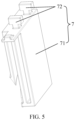
- the wall-mounted toilet system further includes a fixing element 7 mounted on the rear discharge pipe 21, and the fixing element 7 is connected to the wall-mounted bracket 3.
- the fixing element 7 is provided on the rear discharge pipe 21 as a connecting structure to be connected and fixed with the wall-mounted bracket 3, which may play a role of fixing the sewage discharge pipe group 2, and avoid the sewage discharge pipe group 2 being shaken, displaced and the like due to impact from water flow and the like during use.
- a plurality of fixing elements 7 may be provided on the rear discharge pipe 21 to improve the fixing effect of the sewage discharge pipe group 2.
- the fixing element 7 may also be provided on the adjustment pipe 22, which is not limited in the present application.
- the fixing element 7 includes a fixing block 71 and a limiting protrusion 72.
- One end of the fixing block 71 is fixedly connected to the rear discharge pipe 21, and the other end of the fixing block 71 is provided with the limiting protrusion 72.
- the limiting protrusion 72 is snap-fitted with and fixed to the wall-mounted bracket 3.
- the fixing block 71 can be bonded, snap-fitted or screwed with the rear discharge pipe 21, and the limiting protrusion 72 is snap-fitted with and fixed to the wall-mounted bracket 3, so that the connection between the fixing element 7 and the mounted wall is a detachable connection, which is convenient for subsequent replacement and maintenance, etc.
- the fixing element 7 may also be of other forms, for example, the fixing element 7 may be a wire rope for fixed connection.
- the toilet body 1 includes a toilet seat body 11 and a sewage discharge device 12.
- the toilet seat body 11 is provided with a toilet bowl 111 and a sewage discharge port 112 communicated with the toilet bowl 111.
- the toilet seat body 11 is also provided with a mounting cavity 113, and the sewage discharge device 12 is positioned in the mounting cavity 113 and connected with the toilet seat body 11.
- the sewage discharge device 12 is provided with a sewage inlet 121 and a sewage outlet 122, and the sewage inlet 121 is in communication with the sewage discharge port 112.
- the sewage discharge device 12 can be mounted in the mounting cavity 113, and the toilet body 1 does not need to enter the wall, it is different from the traditional wall-mounted toilet that requires a flushing system to be buried in the fake wall. Therefore, there is no need to remove the fake wall during maintenance, cleaning and other operations, and the maintenance operation is relatively convenient.
- the toilet seat body 11 may be made of ceramic, or may be made of stainless steel or other materials.
- the sewage outlet 122 of the toilet body 1 (that is, the sewage outlet 122 of the sewage discharge device 12) can be provided downward, so that the sewage discharge pipe group 2 can directly extend downward to be in communication with the ground sewage discharge pipeline 5 on the ground after being communicated with the sewage outlet 122. It avoids the bending caused by the sewage discharge pipe group 2 extending horizontally first and then extending downward, and reduces the space requirement for the rear of the toilet body 1, such that the sewage discharge pipe group 2 can be conveniently communicated with the ground sewage discharge pipeline 5.
- the sewage discharge device 12 includes a sewage discharge box 123 and a rotary sewage discharge pipe 124 positioned in the sewage discharge box 123.
- An inlet of the rotary sewage discharge pipe 124 is in communication with the sewage inlet 121, and an outlet of the rotary sewage discharge pipe 124 is in communication with the sewage outlet 122.
- the rotary sewage discharge pipe 124 can be rotated relative to the sewage discharge box 123 to discharge sewage.
- the sewage discharge device 12 further includes the sewage discharge box 123, and the rotary sewage discharge pipe 124 is rotatably connected to the sewage inlet 121 of the sewage discharge box 123.
- the sewage in the toilet bowl 111 enters the rotary sewage discharge pipe 124, rotates downward with the rotary sewage discharge pipe 124, is discharged from the rotary sewage discharge pipe 124 under gravity, and is discharged into the sewage discharge pipe group 2 through the sewage outlet 122.
- the sewage discharge function of the wall-mounted toilet can be realized with the rotary sewage discharge pipe 124, such that the original in-wall water tank of the wall-mounted toilet can be eliminated, the product installation is simpler, the maintenance is more concise, and the product cost is more optimized.
- the wall-mounted bracket 3 includes a bracket body, and the bracket body is provided with a wall body 4 connecting portion and a toilet connecting portion.
- the wall body 4 connecting portion is configured to be connected with the wall body 4 so as to arrange the bracket body outside the wall body 4 and to fixed to the wall body 4, and the toilet connecting portion is configured to be connected with the toilet body 1 so as to fix the toilet body 1 to the bracket body.
- the wall-mounted bracket 3 includes a bracket body.
- the wall body 4 connecting portion of the bracket body is used to realize a connection between the wall-mounted bracket 3 and the wall body 4.
- the toilet connecting portion is used for realizing a connection between the wall-mounted bracket 3 and the toilet body 1. Since the bracket body is arranged outside the wall body 4, it is an external wall-mounted bracket 3, which avoids the wall-chiseling or wall-building mounting mode of the traditional wall-mounted toilet product, greatly saves labor and material costs, and reduces the skill requirements for the mounting master. It is not needed to break the wall and then repair the wall during the subsequent maintenance process of the external wall-mounted bracket 3, thus also reducing the subsequent maintenance cost.
- the rear of the toilet seat body 11 may be provided with an inner concave portion for accommodating the wall-mounted bracket 3, so that the wall-mounted bracket 3 is positioned in the inner concave portion after the toilet seat body 11 is connected with the wall-mounted bracket 3. Further, the wall-mounted bracket 3 is covered and shielded by the toilet seat body 11, so as to realize the hiding of the wall-mounted bracket 3 and improve the overall aesthetic appearance of the wall-mounted toilet system.
- connection In the description of the embodiments of the present application, the terms “connection”, “assembly”, and “mounting” should be understood broadly unless otherwise expressly specified and limited.
- connection may be a fixed connection, may be a detachable connection, or may be an integrated connection.
- connection may be a direct connection or an indirect connection through an intermediate medium, and may be an internal communication between two elements.
- specific meanings of the above terms in the present application can be understood according to situations.
- the embodiments of the present application include and contemplate combinations with features and elements known to those of ordinary skill in the art.
- the embodiments, features and elements already disclosed in the embodiments of the present application may also be combined with any conventional features or elements to form the unique technical solutions defined by the claims.
- Any feature or element of any embodiment may also be combined with features or elements from other technical solutions to form another unique technical solution defined by the claims. Accordingly, it should be understood that any of the features shown and/or discussed in the embodiments of the present application may be implemented alone or in any suitable combination.
- the embodiments are not subjected to limitations other than those made in accordance with the appended claims and their equivalent substitutions.
- various modifications and changes may be made within the protection scope of the appended claims.
Landscapes
- Health & Medical Sciences (AREA)
- Life Sciences & Earth Sciences (AREA)
- Engineering & Computer Science (AREA)
- Hydrology & Water Resources (AREA)
- Public Health (AREA)
- Water Supply & Treatment (AREA)
- Sanitary Device For Flush Toilet (AREA)
Applications Claiming Priority (2)
| Application Number | Priority Date | Filing Date | Title |
|---|---|---|---|
| CN202222620175.5U CN218492647U (zh) | 2022-09-30 | 2022-09-30 | 一种挂墙马桶系统 |
| PCT/CN2022/140109 WO2024066082A1 (fr) | 2022-09-30 | 2022-12-19 | Système de toilettes suspendu au mur |
Publications (1)
| Publication Number | Publication Date |
|---|---|
| EP4563761A1 true EP4563761A1 (fr) | 2025-06-04 |
Family
ID=85192840
Family Applications (1)
| Application Number | Title | Priority Date | Filing Date |
|---|---|---|---|
| EP22960677.7A Withdrawn EP4563761A1 (fr) | 2022-09-30 | 2022-12-19 | Système de toilettes suspendu au mur |
Country Status (3)
| Country | Link |
|---|---|
| EP (1) | EP4563761A1 (fr) |
| CN (1) | CN218492647U (fr) |
| WO (1) | WO2024066082A1 (fr) |
Family Cites Families (10)
| Publication number | Priority date | Publication date | Assignee | Title |
|---|---|---|---|---|
| JP2905957B2 (ja) * | 1994-06-21 | 1999-06-14 | 株式会社イナックス | 壁掛け式便器の排便管への接続方法 |
| JPH08302795A (ja) * | 1995-04-28 | 1996-11-19 | Matsushita Electric Works Ltd | サニタリー用配管ユニット |
| CN202899273U (zh) * | 2012-11-13 | 2013-04-24 | 绍兴市同正塑胶管业有限公司 | 一种马桶移位器 |
| CN206916884U (zh) * | 2017-05-23 | 2018-01-23 | 科勒(中国)投资有限公司 | 可调坑距的结构和马桶 |
| CN211774312U (zh) * | 2019-12-20 | 2020-10-27 | 广东集祥陶瓷实业有限公司 | 一种壁挂式分体马桶装置 |
| CN211665878U (zh) * | 2020-01-10 | 2020-10-13 | 深圳市合兴宏塑胶制品有限公司 | 一种可以调节高度的马桶横排管结构 |
| CN213390404U (zh) * | 2020-09-24 | 2021-06-08 | 唐山奇隆洁具有限公司 | 一种挂墙马桶转换为地排马桶的装置 |
| CN214940753U (zh) * | 2021-03-08 | 2021-11-30 | 江门市埏埴卫浴有限公司 | 一种可调控制按板的挂墙马桶入墙水箱 |
| CN216304844U (zh) * | 2021-09-29 | 2022-04-15 | 厦门倍杰特科技有限公司 | 一种马桶排污管装置 |
| CN114411909B (zh) * | 2022-02-10 | 2023-09-29 | 泉州科牧智能厨卫有限公司 | 一种排污盒、排污系统和马桶 |
-
2022
- 2022-09-30 CN CN202222620175.5U patent/CN218492647U/zh active Active
- 2022-12-19 WO PCT/CN2022/140109 patent/WO2024066082A1/fr not_active Ceased
- 2022-12-19 EP EP22960677.7A patent/EP4563761A1/fr not_active Withdrawn
Also Published As
| Publication number | Publication date |
|---|---|
| CN218492647U (zh) | 2023-02-17 |
| WO2024066082A1 (fr) | 2024-04-04 |
Similar Documents
| Publication | Publication Date | Title |
|---|---|---|
| EP4563761A1 (fr) | Système de toilettes suspendu au mur | |
| CN114134970B (zh) | 一种挂墙马桶系统 | |
| CN210739695U (zh) | 一种能够连接不同规格的给排水管道用连接装置 | |
| CN108560671A (zh) | 一种挂墙式座便器 | |
| CN119122068B (zh) | 一种马桶排污装置及马桶 | |
| JP2024546200A (ja) | トイレ本体及びトイレ | |
| CN115404964A (zh) | 一种挂墙马桶系统 | |
| CN202284533U (zh) | 多级泵机封冲洗管的改进结构 | |
| CN221545833U (zh) | 一种排污管 | |
| CN107338845A (zh) | 一种马桶排污装置 | |
| CN216855871U (zh) | 一种二次滤网 | |
| CN217000026U (zh) | 一种新型节水式智能坐马桶 | |
| CN109296046A (zh) | 一种挂墙式马桶 | |
| JPH08109670A (ja) | 便器排水口と排水管との接続方法 | |
| CN210104947U (zh) | 一种建筑物底层下水道防堵塞结构 | |
| JP2005105581A (ja) | 圧送排水機能付き便器 | |
| JP2905957B2 (ja) | 壁掛け式便器の排便管への接続方法 | |
| CN208455775U (zh) | 一种挂墙式座便器 | |
| CN218468272U (zh) | 一种用于真空马桶的蝶阀 | |
| CN208121954U (zh) | 一种市政管道自动冲洗装置 | |
| CN108757496A (zh) | 一种耐酸排污泵 | |
| CN218792576U (zh) | 一款冲牙器机芯的防漏水结构 | |
| CN212455606U (zh) | 一种座便器的分水阀 | |
| CN214305366U (zh) | 一种电液驱动闸阀 | |
| CN219060275U (zh) | 一种圆形支撑承台支撑地漏主体连接器 |
Legal Events
| Date | Code | Title | Description |
|---|---|---|---|
| STAA | Information on the status of an ep patent application or granted ep patent |
Free format text: STATUS: THE INTERNATIONAL PUBLICATION HAS BEEN MADE |
|
| PUAI | Public reference made under article 153(3) epc to a published international application that has entered the european phase |
Free format text: ORIGINAL CODE: 0009012 |
|
| STAA | Information on the status of an ep patent application or granted ep patent |
Free format text: STATUS: REQUEST FOR EXAMINATION WAS MADE |
|
| 17P | Request for examination filed |
Effective date: 20250225 |
|
| AK | Designated contracting states |
Kind code of ref document: A1 Designated state(s): AL AT BE BG CH CY CZ DE DK EE ES FI FR GB GR HR HU IE IS IT LI LT LU LV MC ME MK MT NL NO PL PT RO RS SE SI SK SM TR |
|
| STAA | Information on the status of an ep patent application or granted ep patent |
Free format text: STATUS: THE APPLICATION HAS BEEN WITHDRAWN |
|
| 18W | Application withdrawn |
Effective date: 20250912 |