EP4563762A1 - Ensemble urinoir encastré pour montage mural intégré - Google Patents
Ensemble urinoir encastré pour montage mural intégré Download PDFInfo
- Publication number
- EP4563762A1 EP4563762A1 EP24215568.7A EP24215568A EP4563762A1 EP 4563762 A1 EP4563762 A1 EP 4563762A1 EP 24215568 A EP24215568 A EP 24215568A EP 4563762 A1 EP4563762 A1 EP 4563762A1
- Authority
- EP
- European Patent Office
- Prior art keywords
- collecting container
- arrangement according
- frame
- urinal
- wall
- Prior art date
- Legal status (The legal status is an assumption and is not a legal conclusion. Google has not performed a legal analysis and makes no representation as to the accuracy of the status listed.)
- Granted
Links
Images


Classifications
-
- E—FIXED CONSTRUCTIONS
- E03—WATER SUPPLY; SEWERAGE
- E03D—WATER-CLOSETS OR URINALS WITH FLUSHING DEVICES; FLUSHING VALVES THEREFOR
- E03D13/00—Urinals ; Means for connecting the urinal to the flushing pipe and the wastepipe; Splashing shields for urinals
-
- E—FIXED CONSTRUCTIONS
- E03—WATER SUPPLY; SEWERAGE
- E03D—WATER-CLOSETS OR URINALS WITH FLUSHING DEVICES; FLUSHING VALVES THEREFOR
- E03D11/00—Other component parts of water-closets, e.g. noise-reducing means in the flushing system, flushing pipes mounted in the bowl, seals for the bowl outlet, devices preventing overflow of the bowl contents; devices forming a water seal in the bowl after flushing, devices eliminating obstructions in the bowl outlet or preventing backflow of water and excrements from the waterpipe
- E03D11/12—Swivel-mounted bowls, e.g. for use in restricted spaces slidably or movably mounted bowls; combinations with flushing and disinfecting devices actuated by the swiveling or sliding movement of the bowl
Definitions
- the present invention relates to a concealed urinal arrangement for the integrated wall installation of a urinal in a residential building.
- sanitary facilities in permanently installed residential buildings, so-called real estate. Especially in the private sector, these sanitary facilities are also called toilets or bathrooms. As a room, they are characterized by the fact that the floor and, at least in sections, the walls are tiled to create a comfortable living environment while also allowing for hygienic cleaning and a certain degree of watertightness.
- Micturition refers to the excretion of urine from the urinary bladder of a human body. In men, urination occurs while standing, particularly via the penis.
- this offers the possibility of improved hygiene for the user, as the person urinating does not have to sit down on a toilet, but can urinate while standing.
- this also has disadvantages, especially in private areas.
- a wall-mounted urinal is rather unsightly.
- urine splashes occur.
- Bathrooms, toilets and guest toilets in private areas are often limited in size and dimensions, so that, for example, a conventional toilet and a urinal are located close to one another. If another person sits on the toilet, their gaze or upper body is often close to a wall-mounted urinal, which is perceived as annoying or uncomfortable.
- a urinal that is attached to the wall and protrudes from the wall is usually installed at hand height. If it moves accidentally, a hand could at least touch the edge of a urinal, which is perceived as unhygienic and also annoying.
- the object of the present invention is therefore to create a possibility to improve the function of a urinal and at the same time its visual integration into a property.
- a concealed urinal assembly is claimed, which is suitable for installation in a wall of a property or residential building.
- This can be a permanent installation such that it is embedded in a wall.
- it can also be installed in a drywall or hollow wall.
- a mounting frame is provided, as well as a pivoting collecting container.
- a drain is connected, at least indirectly, to the collecting container, and also, at least indirectly, an inlet for flushing water.
- the urinal is thus installed behind the front surface of a wall and is thus fully integrated into the wall when not in use.
- the collecting container can be swung out of the wall for use.
- the arrangement is characterized in that an outward-facing cover plate of the collecting container has a cover frame with a tile insert for receiving wall tiles, such that it is visually integrated into a tiled wall when the urinal or collecting container is in the pivoted-in, unused state.
- the respective wall surface, in particular a tile is thus placed on the outward-facing cover plate of the collecting container.
- the concealed urinal can thus be visually integrated almost completely into the wall.
- the disadvantage that a neighboring urinal is perceived as disruptive when a person is sitting on a toilet installed in the same bathroom is thus counteracted.
- the visually complete integration also makes it possible for the urinal to be hardly or not at all noticed, and thus the presence of a urinal behind the wall is not perceived as disruptive.
- the installation frame preferably has a height of 70 cm to 140 cm when installed.
- the installation frame is made of a steel material. It can also be made of stainless steel.
- the collecting container is pivotally mounted on or in the installation frame.
- the collecting container has a rear side facing outwards, i.e., towards the wall side or visible side of the wall.
- the rear side in turn, has a cover frame with a tile insert.
- a wall surface, in particular a wall tile can be inserted, in particular glued, into this tile insert.
- the cover frame can slightly or completely overlap the tile itself at the edges. In the closed, pivoted-in state, the collecting container is almost completely integrated into the wall. In the folded state, a barely perceptible circumferential gap remains around the outward-facing cover plate.
- the cover plate or the gap is square or rectangular in frontal or top view.
- the cover has a rounded front view. In the case of a tile cover, for example, this would be cut out using a laser beam and then placed on the cover plate or inserted into the cover frame.
- a so-called cover plate insert can be attached to the cover plate from the outside or inserted into the cover frame.
- This can be, for example, a cover plate with a surface-mounted filler technique. It can also be a decorative plate. The goal is to seamlessly integrate the cover plate into the wall surface surrounding or bordering the built-in urinal.
- the cover plate can also be designed as a trapezoid that increases in size upwards in the vertical direction.
- the collecting container and/or the cover frame are made of a rust-proof stainless steel material.
- the collecting container itself in particular a lower region, is preferably curved or container-shaped.
- a collecting tray is arranged in the installation frame, with the drain or outflow then being located in a lower region of the collecting tray.
- the collecting container can thus be pivoted and tilted.
- Urine conveyed into the collecting container then runs vertically downwards in the lower region of the collecting container and streams, flows, or drips into the collecting tray.
- the collecting tray in turn, then contains a drain, which then conveys the collected urine to a sewer system.
- a siphon or odor trap can be inserted between the urinals.
- a particular advantage is that a odor trap can be installed and maintained from the inside when the urinal is opened.
- a standard siphon located underneath would require the wall in front of it to be opened for replacement or repair.
- a possible maintenance hatch would also visually impair the wall.
- An odor trap can, for example, be a one-sided membrane made of a rubber-like or silicone-like material. Such an odor trap can be serviced or replaced from the inside, thus minimizing maintenance work on a urinal according to the invention and, in particular, completely avoiding destructive installations after installation. The inspection can be performed from the inside.
- a flush also acts in the collecting container or the collecting tray.
- the flush is designed in such a way that when the collecting container is closed, the flush acts in the collecting container and/or the collecting tray. In particular, a spray mist is created. This ensures that any residual urine and urine splashes are rinsed away over as wide a surface as possible, so that, while adhering to hygiene standards, even splashes or residual urine stains do not cause any odors.
- a control system particularly preferably a control module, can be used for the flushing.
- a sensor for example an inductive sensor, is particularly preferably provided for this purpose. When the collecting container is closed, the sensor is triggered.
- a valve connected to a domestic water supply then triggers a flushing process. This valve is particularly electrically or electromagnetically controlled. The control system described above then controls the valve, for example, with a flushing time or opening time of preferably 1 to 30 seconds, in particular 2 to 10 seconds, and can in particular trigger flushing times of 3 seconds, 5 seconds or 8 seconds.
- flushing can be customized for each user, allowing residents of a building to individually select whether they want a shorter or longer flush. This is necessary based on personal preference, as some users only want a short flush and find this sufficient. Other users, on the other hand, prefer a longer flushing cycle, which then includes, for example, a longer or twice as long flushing time.
- control system is preferably visible from the outside, especially when the collection container is open.
- accumulation in the upper area of the opening is then visible and/or operable via small control buttons.
- control unit can also be installed completely behind the wall in the installation frame, allowing it to be operated with indirect visibility when the collection container is open.
- a status LED is located on the control unit to indicate the operating status. When the collection container is opened, a green status LED indicates “System ready,” while a red status LED indicates a malfunction. This eliminates the need to close the collection container and wait for an audible "Flushing completed" signal.
- control system is preferably connected via a local mains connection in Europe. In Germany and many other countries, for example, this is 230 V.
- the valve in particular a cheek valve, can then be connected via a low-voltage range between 10 V and 50 V, particularly preferably 20 V to 30 V, and most preferably 24 V.
- a sensor particularly an inductive sensor. This can also be connected in the aforementioned low-voltage range.
- a corresponding LED module can also be connected.
- the cover plate can be equipped with an automatic push-to-open mechanism, allowing the cover plate to be folded outward at least partially, for example, by pushing against the cover plate toward the wall. This enables seamless integration, so that no external handle or similar device is required to operate the drip tray from a pivoted-in non-use position to a pivoted-out use position.
- a pivot axis is arranged in a lower third of the height of the mounting frame.
- the pivot axis or rotation axis is arranged at least 5 mm above a lower edge of the mounting frame.
- the pivot axis should not be arranged higher than 100 mm, in particular not higher than 60 mm, preferably not higher than 40 mm above a lower edge of the installation space. This makes it possible to ensure pivotability while simultaneously maintaining the gap at the upper and lower edges of the mounting frame. to the rest of the wall, so that only a circumferential gap around the installation frame remains as a visible edge when pivoted in.
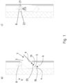
- Figure 1a shows a longitudinal section through a wall 1 of a property not shown in detail.
- a mounting frame 2 In the wall 1 there is a mounting frame 2.
- the mounting frame 2 In the mounting frame 2 itself there is a pivotable collecting container 3.
- the mounting frame 2 itself has a collecting tray 4 in its lower area.
- a mounting plate 23 can also be arranged in a corresponding stud frame of the wall 1.
- the mounting frame 2 of the concealed urinal can then be placed on the mounting plate 23 for later installation.
- the mounting frame 2 itself preferably has a height of 40 cm to 70 cm.
- the mounting frame 2 is positioned 35 cm to 50 cm, in particular 37 cm to 40 cm, preferably 39 cm high from a floor or subsurface.
- the resulting opening 5 for the collecting container 3 is arranged higher in comparison.
- the mounting frame 2 is particularly preferably covered, at least in sections, with a sound coupling and/or sound insulation.
- a sound coupling and/or sound insulation For example, the back of the mounting frame 2 A soundproofing panel, particularly in the form of a bitumen panel, should be installed. Drumming noise would be eliminated at this location.
- a lower opening 5 of the collecting container 3 can then protrude into the collecting tray 4.
- a drain 6 is arranged in the lower area of the collecting tray 4 itself.
- the drain 6 can have a siphon or odor trap (not shown in detail).
- a flushing device is arranged above the collecting container 3 as an inlet 8. This can be automated in the folded state according to Figure 1c triggered by the folding process.
- a sensor 21 can be arranged which detects the unfolded state in Figure 1b ) and folding according to Figure 1c ), after which the collecting container 3 is folded in and then the flushing is triggered.
- a control device 22 can be arranged, which then controls the flushing device.
- the control 22 would not be directly visible. It could be grasped to make adjustments or to maintain the collecting container 3 when dismantling it. However, the control 22 could also be lowered according to Figure 1c ) so that when the collecting container 3 is unfolded, the control 22 would be visible. Furthermore, the control 22 and, if applicable, the valve, and in turn, if applicable, a sensor 21, are particularly preferably arranged on a mounting plate, also called a valve plate. This can then be inserted through the opening 5 of the collecting container 3 in the installation frame 2 from bottom to top in the vertical direction V, so that it Figure 1c shown position. This mounting plate could then be removed for maintenance or adjustment purposes.
- the flushing device then flushes the collecting container 3 and the collecting tray 4, so that the flushing water is also directed to a sewer via the outlet 6 (not shown in detail).
- the flushing device can in particular be designed as a spray device, so that the flushing water is distributed as far as possible all around the entire surface of the The collecting container 3 or the collecting tray 4 is rinsed through.
- the rinsing water then runs over the top 8 of the collecting container 3 into it and through it to the drain 6.
- a rotation axis or pivot axis 9 is arranged.
- a cover plate 10 is formed in the front visible area.
- a tile 11 is inserted into the cover plate 10 itself.
- the cover plate 10 is formed by an externally surrounding cover frame 12.
- the cover frame 12 with the cover plate 10 thus forms a receiving surface or an insert for receiving tiles 11.
- the tile 11 can be glued in here, for example with an assembly adhesive or a tile adhesive or even an assembly tape.
- the tile 11 or several tiles or other surface of the wall 1 is thus cut to the inner size of the cover frame 12 and inserted into the cover frame 12. This enables seamless integration of the wall tiles 13 into the remaining structure.
- the wall 1 itself can be made of plasterboard 14 or gypsum board.
- the concealed urinal arrangement can also, for example, be arranged in a masonry wall.
- a push-button mechanism can be provided in the upper area, relative to the vertical direction, so that for actuation, the upper side of the tile 11 is pressed once and then the collecting container 3 is at least partially swung out and by further folding out, the Figure 1b
- a lower surface 17 can be arranged on the collecting container 3, which then rests on the rear side 18 of the collecting tray 4 and thus limits the pivoting movement.
- a front side 19 of the collecting container 3 can, in turn, be arranged according to Figure 1a in the lower area and thus the swiveling movement
- the pivot axis is arranged in a lower third of the front cover plate 3 relative to the vertical direction, but at least 5 mm, preferably 10 mm above a lower edge 20 of the front cover plate 10.
Landscapes
- Health & Medical Sciences (AREA)
- Life Sciences & Earth Sciences (AREA)
- Engineering & Computer Science (AREA)
- Hydrology & Water Resources (AREA)
- Public Health (AREA)
- Water Supply & Treatment (AREA)
- Sanitary Device For Flush Toilet (AREA)
Priority Applications (1)
| Application Number | Priority Date | Filing Date | Title |
|---|---|---|---|
| EP25215655.9A EP4671457A3 (fr) | 2023-11-28 | 2024-11-26 | Ensemble urinoir encastré pour montage mural intégré |
Applications Claiming Priority (1)
| Application Number | Priority Date | Filing Date | Title |
|---|---|---|---|
| DE202023107041 | 2023-11-28 |
Related Child Applications (2)
| Application Number | Title | Priority Date | Filing Date |
|---|---|---|---|
| EP25215655.9A Division EP4671457A3 (fr) | 2023-11-28 | 2024-11-26 | Ensemble urinoir encastré pour montage mural intégré |
| EP25215655.9A Division-Into EP4671457A3 (fr) | 2023-11-28 | 2024-11-26 | Ensemble urinoir encastré pour montage mural intégré |
Publications (3)
| Publication Number | Publication Date |
|---|---|
| EP4563762A1 true EP4563762A1 (fr) | 2025-06-04 |
| EP4563762B1 EP4563762B1 (fr) | 2026-03-11 |
| EP4563762C0 EP4563762C0 (fr) | 2026-03-11 |
Family
ID=93656167
Family Applications (2)
| Application Number | Title | Priority Date | Filing Date |
|---|---|---|---|
| EP24215568.7A Active EP4563762B1 (fr) | 2023-11-28 | 2024-11-26 | Ensemble urinoir encastré pour montage mural intégré |
| EP25215655.9A Pending EP4671457A3 (fr) | 2023-11-28 | 2024-11-26 | Ensemble urinoir encastré pour montage mural intégré |
Family Applications After (1)
| Application Number | Title | Priority Date | Filing Date |
|---|---|---|---|
| EP25215655.9A Pending EP4671457A3 (fr) | 2023-11-28 | 2024-11-26 | Ensemble urinoir encastré pour montage mural intégré |
Country Status (1)
| Country | Link |
|---|---|
| EP (2) | EP4563762B1 (fr) |
Citations (5)
| Publication number | Priority date | Publication date | Assignee | Title |
|---|---|---|---|---|
| FR1537878A (fr) * | 1967-07-18 | 1968-08-30 | Urinoir mural | |
| DE7317910U (de) * | 1973-05-12 | 1974-07-04 | Grohe F Armaturenfabrik | Urinalbecken |
| DE2541547A1 (de) * | 1975-09-18 | 1977-03-31 | Hans Speich | Urinbecken |
| NL1037689C2 (nl) * | 2010-02-05 | 2011-08-08 | Ronald Johan Solt | Toilet met inklapbaar urinoir. |
| IT201900018950A1 (it) * | 2019-10-16 | 2021-04-16 | Caleffi Spa | Cassetta da incasso per componenti idraulici, in particolare per collettori di impianti sanitari |
Family Cites Families (1)
| Publication number | Priority date | Publication date | Assignee | Title |
|---|---|---|---|---|
| DE4105979A1 (de) * | 1991-02-26 | 1992-08-27 | Walther Dipl Ing Schroeder | Sanitaer-einheit, die aus einem urinalbecken in einer einbaubox mit verschlussklappe und mit anschluessen fuer die versorgungs- und entsorgungsleitungen besteht |
-
2024
- 2024-11-26 EP EP24215568.7A patent/EP4563762B1/fr active Active
- 2024-11-26 EP EP25215655.9A patent/EP4671457A3/fr active Pending
Patent Citations (5)
| Publication number | Priority date | Publication date | Assignee | Title |
|---|---|---|---|---|
| FR1537878A (fr) * | 1967-07-18 | 1968-08-30 | Urinoir mural | |
| DE7317910U (de) * | 1973-05-12 | 1974-07-04 | Grohe F Armaturenfabrik | Urinalbecken |
| DE2541547A1 (de) * | 1975-09-18 | 1977-03-31 | Hans Speich | Urinbecken |
| NL1037689C2 (nl) * | 2010-02-05 | 2011-08-08 | Ronald Johan Solt | Toilet met inklapbaar urinoir. |
| IT201900018950A1 (it) * | 2019-10-16 | 2021-04-16 | Caleffi Spa | Cassetta da incasso per componenti idraulici, in particolare per collettori di impianti sanitari |
Also Published As
| Publication number | Publication date |
|---|---|
| EP4671457A3 (fr) | 2026-03-04 |
| EP4563762B1 (fr) | 2026-03-11 |
| EP4563762C0 (fr) | 2026-03-11 |
| EP4671457A2 (fr) | 2025-12-31 |
Similar Documents
| Publication | Publication Date | Title |
|---|---|---|
| EP2281957B1 (fr) | Agencement de toilettes multifonction | |
| DE20112302U1 (de) | Wasserklosett | |
| DE10226622B4 (de) | Toilette mit Hänge-WC und Klapp-Urinal | |
| DE102014109276B4 (de) | WC-Modul mit Unterputzspülkasten für ein Dusch-WC mit integriertem, abgesichertem Frischwasseranschluss | |
| DE10025348A1 (de) | Kombinierte Toilette | |
| DE202006020903U1 (de) | Installationsvorrichtung für eine sanitäre Einrichtung und sanitäre Einrichtung mit einer solchen Installationsvorrichtung | |
| EP4563762B1 (fr) | Ensemble urinoir encastré pour montage mural intégré | |
| DE2541547A1 (de) | Urinbecken | |
| DE102009005319B4 (de) | Multifunktionale Toilettenanordnung | |
| DE102007048912B4 (de) | Kombi-Spültoilette und Toilettenaufsatz für ein Sitztoilettenbecken | |
| DE202023002350U1 (de) | Spülsystem für ein Hänge-WC | |
| CH701009A2 (de) | Sanitäre Anlage. | |
| DE29903954U1 (de) | Zum Urinal verstellbare Toiletten-Vorrichtung | |
| DE10120896C2 (de) | Sanitäranlage | |
| DE202010003453U1 (de) | WC-Schüssel (Keramik) für Dusch-WC | |
| DE10258275B3 (de) | Toilette mit Urinal | |
| DE20219355U1 (de) | Toilette mit Urinal | |
| DE202012012715U1 (de) | Sitz-WC-Becken mit integriertem Urinal | |
| DE29912467U1 (de) | Urinal | |
| DE29717366U1 (de) | Urinal-Schleuse für sämtliche WC-Anlagen | |
| DE10104316A1 (de) | WC mit direkter Vor-Ort-Entlüftung | |
| DE29908960U1 (de) | Sitz für eine Toilette | |
| DE102004051636B4 (de) | Ersatz-Urinal | |
| EP1367187A3 (fr) | Kit pour élément sanitaire de chasse d'eau | |
| DE29806446U1 (de) | Compact-Urinal-Anlage für Unterputz |
Legal Events
| Date | Code | Title | Description |
|---|---|---|---|
| PUAI | Public reference made under article 153(3) epc to a published international application that has entered the european phase |
Free format text: ORIGINAL CODE: 0009012 |
|
| STAA | Information on the status of an ep patent application or granted ep patent |
Free format text: STATUS: REQUEST FOR EXAMINATION WAS MADE |
|
| 17P | Request for examination filed |
Effective date: 20250402 |
|
| AK | Designated contracting states |
Kind code of ref document: A1 Designated state(s): AL AT BE BG CH CY CZ DE DK EE ES FI FR GB GR HR HU IE IS IT LI LT LU LV MC ME MK MT NL NO PL PT RO RS SE SI SK SM TR |
|
| STAA | Information on the status of an ep patent application or granted ep patent |
Free format text: STATUS: EXAMINATION IS IN PROGRESS |
|
| 17Q | First examination report despatched |
Effective date: 20250630 |
|
| RAP1 | Party data changed (applicant data changed or rights of an application transferred) |
Owner name: SAUERMANN, TIMM |
|
| RIN1 | Information on inventor provided before grant (corrected) |
Inventor name: SAUERMANN, TIMM |
|
| GRAP | Despatch of communication of intention to grant a patent |
Free format text: ORIGINAL CODE: EPIDOSNIGR1 |
|
| STAA | Information on the status of an ep patent application or granted ep patent |
Free format text: STATUS: GRANT OF PATENT IS INTENDED |
|
| GRAJ | Information related to disapproval of communication of intention to grant by the applicant or resumption of examination proceedings by the epo deleted |
Free format text: ORIGINAL CODE: EPIDOSDIGR1 |
|
| STAA | Information on the status of an ep patent application or granted ep patent |
Free format text: STATUS: EXAMINATION IS IN PROGRESS |
|
| GRAP | Despatch of communication of intention to grant a patent |
Free format text: ORIGINAL CODE: EPIDOSNIGR1 |
|
| STAA | Information on the status of an ep patent application or granted ep patent |
Free format text: STATUS: GRANT OF PATENT IS INTENDED |
|
| INTG | Intention to grant announced |
Effective date: 20250924 |
|
| INTC | Intention to grant announced (deleted) | ||
| INTG | Intention to grant announced |
Effective date: 20251023 |
|
| GRAJ | Information related to disapproval of communication of intention to grant by the applicant or resumption of examination proceedings by the epo deleted |
Free format text: ORIGINAL CODE: EPIDOSDIGR1 |
|
| STAA | Information on the status of an ep patent application or granted ep patent |
Free format text: STATUS: EXAMINATION IS IN PROGRESS |
|
| GRAP | Despatch of communication of intention to grant a patent |
Free format text: ORIGINAL CODE: EPIDOSNIGR1 |
|
| STAA | Information on the status of an ep patent application or granted ep patent |
Free format text: STATUS: GRANT OF PATENT IS INTENDED |
|
| INTC | Intention to grant announced (deleted) | ||
| GRAS | Grant fee paid |
Free format text: ORIGINAL CODE: EPIDOSNIGR3 |
|
| GRAA | (expected) grant |
Free format text: ORIGINAL CODE: 0009210 |
|
| STAA | Information on the status of an ep patent application or granted ep patent |
Free format text: STATUS: THE PATENT HAS BEEN GRANTED |
|
| INTG | Intention to grant announced |
Effective date: 20260120 |
|
| AK | Designated contracting states |
Kind code of ref document: B1 Designated state(s): AL AT BE BG CH CY CZ DE DK EE ES FI FR GB GR HR HU IE IS IT LI LT LU LV MC ME MK MT NL NO PL PT RO RS SE SI SK SM TR |
|
| REG | Reference to a national code |
Ref country code: CH Ref legal event code: F10 Free format text: ST27 STATUS EVENT CODE: U-0-0-F10-F00 (AS PROVIDED BY THE NATIONAL OFFICE) Effective date: 20260311 Ref country code: GB Ref legal event code: FG4D Free format text: NOT ENGLISH |
|
| REG | Reference to a national code |
Ref country code: DE Ref legal event code: R096 Ref document number: 502024000858 Country of ref document: DE |
|
| REG | Reference to a national code |
Ref country code: IE Ref legal event code: FG4D Free format text: LANGUAGE OF EP DOCUMENT: GERMAN |