EP4563764A1 - Système de soupape d'urgence - Google Patents
Système de soupape d'urgence Download PDFInfo
- Publication number
- EP4563764A1 EP4563764A1 EP23213071.6A EP23213071A EP4563764A1 EP 4563764 A1 EP4563764 A1 EP 4563764A1 EP 23213071 A EP23213071 A EP 23213071A EP 4563764 A1 EP4563764 A1 EP 4563764A1
- Authority
- EP
- European Patent Office
- Prior art keywords
- valve system
- emergency valve
- valve
- emergency
- closing plate
- Prior art date
- Legal status (The legal status is an assumption and is not a legal conclusion. Google has not performed a legal analysis and makes no representation as to the accuracy of the status listed.)
- Pending
Links
Images


Classifications
-
- E—FIXED CONSTRUCTIONS
- E03—WATER SUPPLY; SEWERAGE
- E03F—SEWERS; CESSPOOLS
- E03F5/00—Sewerage structures
- E03F5/04—Gullies inlets, road sinks, floor drains with or without odour seals or sediment traps
- E03F5/041—Accessories therefor
- E03F5/0411—Devices for temporarily blocking inflow into a gully
-
- E—FIXED CONSTRUCTIONS
- E03—WATER SUPPLY; SEWERAGE
- E03F—SEWERS; CESSPOOLS
- E03F5/00—Sewerage structures
- E03F5/10—Collecting-tanks; Equalising-tanks for regulating the run-off; Laying-up basins
- E03F5/105—Accessories, e.g. flow regulators or cleaning devices
- E03F5/107—Active flow control devices, i.e. moving during flow regulation
-
- E—FIXED CONSTRUCTIONS
- E03—WATER SUPPLY; SEWERAGE
- E03F—SEWERS; CESSPOOLS
- E03F7/00—Other installations or implements for operating sewer systems, e.g. for preventing or indicating stoppage; Emptying cesspools
- E03F7/02—Shut-off devices
-
- F—MECHANICAL ENGINEERING; LIGHTING; HEATING; WEAPONS; BLASTING
- F16—ENGINEERING ELEMENTS AND UNITS; GENERAL MEASURES FOR PRODUCING AND MAINTAINING EFFECTIVE FUNCTIONING OF MACHINES OR INSTALLATIONS; THERMAL INSULATION IN GENERAL
- F16K—VALVES; TAPS; COCKS; ACTUATING-FLOATS; DEVICES FOR VENTING OR AERATING
- F16K31/00—Actuating devices; Operating means; Releasing devices
- F16K31/02—Actuating devices; Operating means; Releasing devices electric; magnetic
- F16K31/04—Actuating devices; Operating means; Releasing devices electric; magnetic using a motor
-
- F—MECHANICAL ENGINEERING; LIGHTING; HEATING; WEAPONS; BLASTING
- F16—ENGINEERING ELEMENTS AND UNITS; GENERAL MEASURES FOR PRODUCING AND MAINTAINING EFFECTIVE FUNCTIONING OF MACHINES OR INSTALLATIONS; THERMAL INSULATION IN GENERAL
- F16K—VALVES; TAPS; COCKS; ACTUATING-FLOATS; DEVICES FOR VENTING OR AERATING
- F16K31/00—Actuating devices; Operating means; Releasing devices
- F16K31/44—Mechanical actuating means
- F16K31/50—Mechanical actuating means with screw-spindle or internally threaded actuating means
- F16K31/508—Mechanical actuating means with screw-spindle or internally threaded actuating means the actuating element being rotatable, non-rising, and driving a non-rotatable axially-sliding element
Definitions
- This application relates generally to emergency valve systems that regulate stormwater volumes exiting drainage inlets or flowing through pipe networks. More particularly, the novel emergency valve system can be electrically/manually activated to block contaminated spills.
- Stormwater runoff conveyed from urbanized and industrialized areas into drainage networks may contain contaminants such as suspended solids, hydrocarbons, microplastics, toxic heavy metals, nutrients, that need to be stopped before being released into water bodies.
- the blockage of such contaminated stormwater runoff can be achieved within the drainage inlets that receive and collects the said contaminated stormwater runoff, or further downstream within the drainage pipe network.
- Patent US2003094407A1 describes a filter assembly that filters water, particularly stormwater, that includes flow regulating, siphon inducing, and surface cleaning features that allow the filter assembly to operate at the design filtration rate for an extended period.
- water flows inward through an annular filter medium into a drain manifold.
- the rate of flow into the drain manifold is controlled by a float valve assembly.
- a check valve permits air to escape, but not enter, the filter assembly creating a siphon effect when the rate of flow into the drain manifold is increased.
- Patent EP4070001A1 describes a rotary valve and float assembly for controlling a flow of liquid into a container including a plug valve portion and a divider portion.
- the plug valve portion including a set of plugs that seal against a set of openings in the divider portion when the rotary valve is in a closed position. Movement of the rotary valve between open and closed positions is controlled by the movement of the float assembly in the container.
- the float assembly typically moves according to a liquid level within the container.
- Patent EP4070001A1 allows control of flowrate entering collection tanks, reservoirs, or other liquid storage containers, it's poorly fitted for blocking stormwater discharges from drainage inlets. Moreover, the invention does not include a motorised control of the valve opening/closing mechanism.
- the present invention provides a novel emergency valve system for blocking contaminated stormwater runoff.
- the invention can be implemented to regulate and block stormwater runoff discharges exiting drainage inlets, or it can be installed within pipe networks.
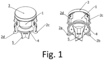
- the invention comprises: a valve body, which forms the backbone of the emergency valve system and provides rigidity and mechanical resistance to the valve system; valve frame, which allows the emergency valve system to be secured to drainage inlets; valve cover, to protect the internal components of the emergency valve system from the external environment; closing plate, implemented to regulate flow discharges from the drainage inlet where said emergency valve system is installed; baffle plates, designed to decrease the air content in the flow discharged through the emergency valve system, and therefore increasing the flow capacity of the valve; actuator screw, which allows the closing plate to be raised or lowered; protection cover, to protect the actuator screw from the external environment.
- the emergency valve system may be: a) electrically operated by including a motor inserted between the valve body and the valve cover, engaged to the actuator screw, to rotate the said actuator screw and therefore raising or lowering the closing plate; or b) manually operated by including an external adjusting screw engaged with the actuator screw, so that the closing plate can be raised or lowered by rotating the said external adjusting screw.
- the invention may include a battery to power the motor, and/or a power cord to power the motor from an external power supply system.
- the invention may also include one on several water sensor probes attached to the valve body to monitor the water quality.
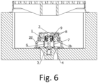
- Typical configurations include: a) valve system placed within a drainage inlet on top of an outlet pipe; b) valve system placed within control chamber along drainage pipe network, oriented so that the closing plate is perpendicular to the discharge direction.
- the emergency valve system allows a quick and efficient blockage of contaminated stormwater runoff or accidental spills before they reach the receiving water bodies.
- the invention can be installed in a variety of drainage inlets, including airports, ports, terminals, as well as general industrial sites, parking lots, service stations, restaurants, residences, and multi-family housing. Additionally, no invasive building or civil work is required for the installation, and the architecture of the drainage inlets does not need to be changed.
- valve body 1 valve frame 2
- valve cover 3 closing plate 4
- baffle plates 5 actuator screw 6 protection cover 7.
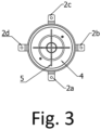
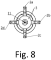
- valve frame 2 consists of four (4) valve feet 2a, 2b, 2c, 2d allowing the valve system to be secured to an external support (the external support varies based on the emergency valve implementation, ex: drainage inlet walls). Moreover, the components of the said emergency valve system are fastened by bolted joints 10.
- the valve body 1 forms the backbone of the valve system and provides rigidity and mechanical resistance to the valve system.
- the number and position of the valve feet 2 may vary to be adapted to specific installation.
- the valve cover 3 protects the internal components of the emergency valve system from the external environment.
- the closing plate 4 allows the valve system to regulate flow discharges.
- the baffle plates 5 are designed to decrease the air content in the flow discharged through the emergency valve system, and therefore increasing the flow capacity of the valve.
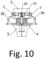
- the actuator screw 6 runs along the vertical axis of the valve system, is engaged to the closing plate 4 and allows the said closing plate 4 to be raised or lowered.
- the protection cover 7 protects the actuator screw 6 from the external environment.
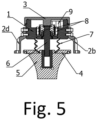
- Drawings Fig. 1 , Fig. 2 , Fig. 3 , Fig. 4 , Fig. 5 show an embodiment of the present invention in which the valve system also features a motor 8 and a battery 9 to power the motor 8 (motor 8 and battery 9 are inserted between the valve body 1 and valve cover 3 ).
- the actuator screw 6 is engaged and moved by the motor 8, inserted between valve body 1 and valve cover 3, and concentrical to the said actuator screw 6.
- the actuator screw 6 rotates along its vertical axis, raising or lowering the closing plate.
- a typical implementation of such configuration is on top of a pipe exiting a drainage inlet, to regulate and block the outlet discharge, as shown in Fig. 6 .
- Drawings Fig. 7 , Fig. 8 , Fig. 9 , Fig. 10 , Fig. 11 show an embodiment of the present invention in which the valve system features an external adjusting screw 11 engaged with the actuator screw 6, so that the closing plate can be manually raised or lowered by rotating the external adjusting screw.
Landscapes
- Engineering & Computer Science (AREA)
- General Engineering & Computer Science (AREA)
- Health & Medical Sciences (AREA)
- Life Sciences & Earth Sciences (AREA)
- Hydrology & Water Resources (AREA)
- Public Health (AREA)
- Water Supply & Treatment (AREA)
- Mechanical Engineering (AREA)
- Electrically Driven Valve-Operating Means (AREA)
Priority Applications (1)
| Application Number | Priority Date | Filing Date | Title |
|---|---|---|---|
| EP23213071.6A EP4563764A1 (fr) | 2023-11-29 | 2023-11-29 | Système de soupape d'urgence |
Applications Claiming Priority (1)
| Application Number | Priority Date | Filing Date | Title |
|---|---|---|---|
| EP23213071.6A EP4563764A1 (fr) | 2023-11-29 | 2023-11-29 | Système de soupape d'urgence |
Publications (1)
| Publication Number | Publication Date |
|---|---|
| EP4563764A1 true EP4563764A1 (fr) | 2025-06-04 |
Family
ID=89029852
Family Applications (1)
| Application Number | Title | Priority Date | Filing Date |
|---|---|---|---|
| EP23213071.6A Pending EP4563764A1 (fr) | 2023-11-29 | 2023-11-29 | Système de soupape d'urgence |
Country Status (1)
| Country | Link |
|---|---|
| EP (1) | EP4563764A1 (fr) |
Citations (10)
| Publication number | Priority date | Publication date | Assignee | Title |
|---|---|---|---|---|
| US5569372A (en) * | 1994-07-13 | 1996-10-29 | Her Majesty The Queen In Right Of Canada As Represented By The Minister Of Transport Canada | Catch basin structure for interception of contaminants having detachable parts |
| WO1998051951A1 (fr) * | 1997-05-14 | 1998-11-19 | Fisher Controls International, Inc. | Stabilisateur de debit a aubes multiples pour robinets d'etranglement |
| US20030094407A1 (en) | 2001-11-20 | 2003-05-22 | Stormwater Management, Inc. | Filter cartridge with regulated surface cleaning mechanism |
| KR200381877Y1 (ko) * | 2005-02-04 | 2005-04-15 | 주식회사 보성Eng | 선박갑판배수구용 밸브 |
| KR200384889Y1 (ko) * | 2005-02-04 | 2005-05-23 | 주식회사 보성Eng | 선박갑판배수구용 밸브 |
| CN204662631U (zh) * | 2015-04-09 | 2015-09-23 | 天津博弘化工有限责任公司 | 一种排水口挡板 |
| US20170183243A1 (en) * | 2015-03-26 | 2017-06-29 | Doug Reitmeyer | Systems and arrangements for mitigating environmental damage caused by storm water carried pollution |
| KR102266632B1 (ko) * | 2020-11-26 | 2021-06-18 | 김인식 | 액체배출 및 차단작동이 효과적으로 이루어지는 배수공의 개폐밸브 |
| EP3957802A1 (fr) * | 2020-08-19 | 2022-02-23 | Scherzer Umwelttechnik GmbH | Soupape pour égout |
| EP4070001A1 (fr) | 2019-12-04 | 2022-10-12 | Stormwell Inc. | Vanne rotative |
-
2023
- 2023-11-29 EP EP23213071.6A patent/EP4563764A1/fr active Pending
Patent Citations (10)
| Publication number | Priority date | Publication date | Assignee | Title |
|---|---|---|---|---|
| US5569372A (en) * | 1994-07-13 | 1996-10-29 | Her Majesty The Queen In Right Of Canada As Represented By The Minister Of Transport Canada | Catch basin structure for interception of contaminants having detachable parts |
| WO1998051951A1 (fr) * | 1997-05-14 | 1998-11-19 | Fisher Controls International, Inc. | Stabilisateur de debit a aubes multiples pour robinets d'etranglement |
| US20030094407A1 (en) | 2001-11-20 | 2003-05-22 | Stormwater Management, Inc. | Filter cartridge with regulated surface cleaning mechanism |
| KR200381877Y1 (ko) * | 2005-02-04 | 2005-04-15 | 주식회사 보성Eng | 선박갑판배수구용 밸브 |
| KR200384889Y1 (ko) * | 2005-02-04 | 2005-05-23 | 주식회사 보성Eng | 선박갑판배수구용 밸브 |
| US20170183243A1 (en) * | 2015-03-26 | 2017-06-29 | Doug Reitmeyer | Systems and arrangements for mitigating environmental damage caused by storm water carried pollution |
| CN204662631U (zh) * | 2015-04-09 | 2015-09-23 | 天津博弘化工有限责任公司 | 一种排水口挡板 |
| EP4070001A1 (fr) | 2019-12-04 | 2022-10-12 | Stormwell Inc. | Vanne rotative |
| EP3957802A1 (fr) * | 2020-08-19 | 2022-02-23 | Scherzer Umwelttechnik GmbH | Soupape pour égout |
| KR102266632B1 (ko) * | 2020-11-26 | 2021-06-18 | 김인식 | 액체배출 및 차단작동이 효과적으로 이루어지는 배수공의 개폐밸브 |
Similar Documents
| Publication | Publication Date | Title |
|---|---|---|
| US20110062088A1 (en) | Fluid filter system and related method | |
| US7638066B1 (en) | Flow control structure and related media filtration system | |
| AU2006238940B2 (en) | Storm drain filter | |
| US5569372A (en) | Catch basin structure for interception of contaminants having detachable parts | |
| US6848465B1 (en) | Dual-action vent check valve | |
| US20150202552A1 (en) | Liquid filter drain with integral air vent | |
| AU2004261653A1 (en) | Stormwater treatment system | |
| US20170183243A1 (en) | Systems and arrangements for mitigating environmental damage caused by storm water carried pollution | |
| US10174495B2 (en) | Oil leak detection circuit and blocking mechanism for use in a storm water drainage system | |
| EP4563764A1 (fr) | Système de soupape d'urgence | |
| US7445704B2 (en) | Oil separation apparatus | |
| US9963358B2 (en) | Oil stop valve assembly | |
| KR101608043B1 (ko) | 비점오염 처리 시설 | |
| KR102590283B1 (ko) | 회전 방향을 조절하여 선택적 위치의 시료 분배 기능이 구비된 샘플링 컨트롤 시스템 | |
| KR102954508B1 (ko) | 친환경 다목적 수행이 가능한 저류조 구조물 | |
| WO2006106343A1 (fr) | Soupape de fermeture | |
| US11298636B2 (en) | Oil monitoring system | |
| EP2177678B1 (fr) | Vanne de contrôle de pollution, système de drainage et procédé | |
| EP2909112B1 (fr) | Système de prévention de soupape de trop-plein | |
| US20100319115A1 (en) | Methods and apparatus for sealing a drain | |
| KR100700024B1 (ko) | 수중 오염물질 처리장치 | |
| US7597802B2 (en) | Drain filtration apparatus | |
| HU208177B (en) | Sampler for liquids, in particular to small-dimension sewage conduits | |
| WO2019112591A1 (fr) | Ensemble vanne d'arrêt d'huile |
Legal Events
| Date | Code | Title | Description |
|---|---|---|---|
| PUAI | Public reference made under article 153(3) epc to a published international application that has entered the european phase |
Free format text: ORIGINAL CODE: 0009012 |
|
| STAA | Information on the status of an ep patent application or granted ep patent |
Free format text: STATUS: THE APPLICATION HAS BEEN PUBLISHED |
|
| AK | Designated contracting states |
Kind code of ref document: A1 Designated state(s): AL AT BE BG CH CY CZ DE DK EE ES FI FR GB GR HR HU IE IS IT LI LT LU LV MC ME MK MT NL NO PL PT RO RS SE SI SK SM TR |
|
| STAA | Information on the status of an ep patent application or granted ep patent |
Free format text: STATUS: REQUEST FOR EXAMINATION WAS MADE |
|
| 17P | Request for examination filed |
Effective date: 20260211 |
|
| STAA | Information on the status of an ep patent application or granted ep patent |
Free format text: STATUS: THE APPLICATION IS DEEMED TO BE WITHDRAWN |