EP4563770A1 - Verlängerungsmast - Google Patents
Verlängerungsmast Download PDFInfo
- Publication number
- EP4563770A1 EP4563770A1 EP24216496.0A EP24216496A EP4563770A1 EP 4563770 A1 EP4563770 A1 EP 4563770A1 EP 24216496 A EP24216496 A EP 24216496A EP 4563770 A1 EP4563770 A1 EP 4563770A1
- Authority
- EP
- European Patent Office
- Prior art keywords
- pole
- pole section
- section
- main
- extension
- Prior art date
- Legal status (The legal status is an assumption and is not a legal conclusion. Google has not performed a legal analysis and makes no representation as to the accuracy of the status listed.)
- Pending
Links
Images


Classifications
-
- E—FIXED CONSTRUCTIONS
- E04—BUILDING
- E04H—BUILDINGS OR LIKE STRUCTURES FOR PARTICULAR PURPOSES; SWIMMING OR SPLASH BATHS OR POOLS; MASTS; FENCING; TENTS OR CANOPIES, IN GENERAL
- E04H12/00—Towers; Masts or poles; Chimney stacks; Water-towers; Methods of erecting such structures
- E04H12/18—Towers; Masts or poles; Chimney stacks; Water-towers; Methods of erecting such structures movable or with movable sections, e.g. rotatable or telescopic
-
- E—FIXED CONSTRUCTIONS
- E04—BUILDING
- E04G—SCAFFOLDING; FORMS; SHUTTERING; BUILDING IMPLEMENTS OR AIDS, OR THEIR USE; HANDLING BUILDING MATERIALS ON THE SITE; REPAIRING, BREAKING-UP OR OTHER WORK ON EXISTING BUILDINGS
- E04G17/00—Connecting or other auxiliary members for forms, falsework structures, or shutterings
- E04G17/14—Bracing or strutting arrangements for formwalls; Devices for aligning forms
-
- E—FIXED CONSTRUCTIONS
- E04—BUILDING
- E04G—SCAFFOLDING; FORMS; SHUTTERING; BUILDING IMPLEMENTS OR AIDS, OR THEIR USE; HANDLING BUILDING MATERIALS ON THE SITE; REPAIRING, BREAKING-UP OR OTHER WORK ON EXISTING BUILDINGS
- E04G21/00—Preparing, conveying, or working-up building materials or building elements in situ; Other devices or measures for constructional work
- E04G21/24—Safety or protective measures preventing damage to building parts or finishing work during construction
- E04G21/243—Safety or protective measures preventing damage to building parts or finishing work during construction for creating a temporary partition in a closed room
-
- E—FIXED CONSTRUCTIONS
- E04—BUILDING
- E04G—SCAFFOLDING; FORMS; SHUTTERING; BUILDING IMPLEMENTS OR AIDS, OR THEIR USE; HANDLING BUILDING MATERIALS ON THE SITE; REPAIRING, BREAKING-UP OR OTHER WORK ON EXISTING BUILDINGS
- E04G21/00—Preparing, conveying, or working-up building materials or building elements in situ; Other devices or measures for constructional work
- E04G21/24—Safety or protective measures preventing damage to building parts or finishing work during construction
- E04G21/30—Safety or protective measures preventing damage to building parts or finishing work during construction against mechanical damage or dirt, e.g. guard covers of stairs
Definitions
- the present disclosure is directed to partition systems that are used to separate portions of a building or room, particularly to an extension pole that is used in a partition system, and more particularly to a collapsible and extendable extension pole according to the preamble of claim 1 that is used in a partition system to a partition system according to the preamble of claim 14, and to a method of forming a partition wall according to the preamble of claim 15.
- Partition systems are commonly used to form a barrier to dirt, paint spray, dust, noise, light, odors, and the like. Partition systems can be used in construction zones to maintain a clear region outside the partitioned zone.
- the partition systems are typically formed of one or more poles that support a barrier material such plastic sheeting, fabric sheeting, or the like to a ceiling, wall, etc. However, other arrangements such as tape, nails, tacks, etc., can also or alternatively be used to support the barrier material.
- An opening can optionally be formed in the barrier material to allow access to the partitioned zone. Such opening can be cut or otherwise formed in the barrier material.
- a zipper, magnet closure arrangement, hook and loop fastener arrangement, snaps and the like can be used to enable the opening in the barrier material to be opened and closed.
- extension poles have been developed to supporting a barrier system (See US Patent Nos. 4,794,974 ; 4,708,189 ; 5,308,280 ; 5,924,469 ; 7,658,219 ; 8,857,499 ; 10,689,865 ; 10,781,597 ; 11,530,542 ; US Publication Nos. 2021/0404198 and 2022/0081963 , all of which are incorporated herein by reference).
- extension poles can be successfully used to provide temporary support for a barrier material, these extension poles are bulky and inconvenient to store, take up significant shelf-space in retail stores, and can be difficult and/or inconvenient to store and/or transport.
- the present disclosure is directed to a partition system that is used to separate portions of a building or room, and wherein the partition system includes a collapsible and extendable extension pole.
- the present disclosure is also directed to a method for using a partition system to separate portions of a building or room, and further to a method of storing and using a collapsible and extendable extension pole with a partition system.
- the partition system in accordance with the present disclosure can be used in construction zones, room, etc., to form a barrier to dirt, paint spray, dust, noise, light, odors, and the like.
- the partition system can be configured for use as a temporary or permanent barrier.
- a partition system that includes a) one or more specially configured collapsible and extendable extension poles, b) a barrier material (e.g., plastic sheeting, fabric sheeting, composite material sheeting, etc.), and c) an optional opening arrangement (e.g., zipper, magnet closure arrangement, hook and loop fastener arrangement, snaps, etc.) that can be used to form an openable and closable opening in the barrier material.
- a barrier material e.g., plastic sheeting, fabric sheeting, composite material sheeting, etc.
- an optional opening arrangement e.g., zipper, magnet closure arrangement, hook and loop fastener arrangement, snaps, etc.
- the collapsible and extendable extension pole includes a) a plurality of pole sections, b) a pole section connection arrangement, c) an optional barrier material connection arrangement, d) an optional grip pad, e) an optional compression base portion, f) an optional non-slip foot arrangement, g) one or more optional pole clip arrangements, and/or g) one or more optional tether arrangements.
- the plurality of pole sections of the collapsible and extendable extension pole includes a) a main pole body section, and b) one or both of a removable top pole section and a removable bottom pole section.
- the main pole section can be a single pole section or include one or more telescoping sections (e.g., 1-10 telescoping sections and all values and ranges therebetween).
- the main pole section includes two pole sections that are arranged in a telescoping configuration.
- the main pole section includes three pole sections that are arranged in a telescoping configuration.
- the main pole section can be formed of more than three telescoping sections.
- the single pole section is generally 1-25 ft. (and all values and ranges therebetween); however, other lengths can be used.
- each of the pole sections is generally 0.25-15 ft. (and all values and ranges therebetween); however, other lengths can be used.
- the main pole section includes two or more pole sections, and the length of each of the pole sections is 0.5-8 feet.
- the main pole section includes two or more pole sections, and the length of each of the pole sections is 2-5 feet.
- the main pole section includes two or more pole sections, and the length of each of the pole sections is 2.5-4 feet.
- the length of two or more pole sections can be the same, or two or more of the pole sections can be different lengths.
- the cross-sectional shape and size of each of the pole sections of the main pole section can be constant along 50-100% of the longitudinal length of the pole section; however, this is not required.
- the cross-sectional shape of two or more of the pole sections of the main pole section can be same along 50-100% of the longitudinal length of the pole section; however, this is not required.
- the cross-sectional size of two or more of the pole sections of the main pole section can be different along 50-100% of the longitudinal length of the pole section; however, this is not required.
- each of the one or more pole sections of the main pole section have a tubular shape along 70-100% of the longitudinal length of each of the pole sections, and the cross-sectional shape and area of each of the pole sections, when the main pole section includes two or more pole sections, is selected so that the pole sections can be telescopically fitted together so that pole section can be telescopically extended and collapsed with respect to one another.
- the main pole section can be configured to provide most or all of the height/longitudinal length adjustment to the collapsible and extendable extension pole that is required; however, this is not required.
- one or more of the pole sections optionally includes a releasable locking arrangement that allows a user to releasably lock two pole sections relative to one another in position once the two telescoping pole sections have been expanded or contracted in a desired position with respect to one another.
- a releasable locking arrangement that allows a user to releasably lock two pole sections relative to one another in position once the two telescoping pole sections have been expanded or contracted in a desired position with respect to one another.
- Many such locking arrangements are well known in the art with regard to telescoping poles (e.g., internal twist action telescopic pole locking system, internal push button telescopic pole locking system, external twist action telescopic pole clamping system, clamp arrangement, cable or pin locking arrangement, etc.), thus will note be further described herein.
- the releasable locking arrangement inhibits or prevents full separation of two telescoping pole sections from one another.
- the outer surface of one or more of the pole sections of the main pole section can optionally include a gripping surface/structures (e.g., rough surface, grooved surface, ribbed surface, polymer- or rubber-coated surface, collar, outer sleeve, etc.) to facilitate in the gripping of one or more of the pole sections.
- a gripping surface/structures e.g., rough surface, grooved surface, ribbed surface, polymer- or rubber-coated surface, collar, outer sleeve, etc.
- the number, size, configuration and material of the one or more gripping surfaces/structures are non-limiting.
- one or more gripping surface/structures can be located at the top edge, top edge portion, bottom edge and/or bottom edge portion of one or more of the pole sections.
- the top portion of the main pole section can optionally include a) an optional barrier material connection arrangement, b) an optional pole clip arrangement, c) an optional grip pad, d) an optional compressible top portion, e) an optional male fitting, f) an optional threaded connection arrangement, g) an optional tether connection arrangement, i) an optional outer gripping surface, and/or j) an optional pole clip arrangement.
- the top or top portion of the main pole section optionally includes an optional barrier material connection arrangement, an optional pole clip arrangement, and/or an optional grip pad.
- the optional barrier material connection arrangement, optional pole clip arrangement, and/or optional grip pad can be configured to facilitate in temporarily or permanently connect a portion of the barrier material to the top or top portion of the main pole section.
- the configuration of the optional barrier material connection arrangement, optional pole clip arrangement, and/or optional grip pad is non-limiting (e.g., clip, clamp, adhesive surface, hooks, prongs, straps, hook and look fasteners, sleeve clamp, rough pad surface, needle or nail surface, use of a cord or wire or rubber band or bungee cord, hook and loop fastener, mushroom connectors, etc.).
- Non-limiting connection arrangements that can be used are disclosed in US 5,924,469 ; US 7,658,219 ; US 8,857,499 ; US 10,689,865 ; US 10,781,597 ; US 11,530,542 ; and US Publication Nos.
- the optional barrier material connection arrangement, the optional grip pad, and/or the optional pole clip arrangement can optionally be removably detachable to the top portion of the main pole section; however, this is not required.
- the optional barrier material connection arrangement, the optional grip pad, and/or the optional pole clip arrangement can optionally be pivotally and/or rotatably connected, or rigidly connected to the top or top portion of the main pole section.
- the optional barrier material connection arrangement, the optional grip pad, and/or the optional pole clip arrangement can optionally be partially or fully removably connected to the top or top portion of the main pole section, or permanently connected to the top or top portion of the main pole section.
- the top or top portion of the main pole section includes a grip pad and/or a pole clip arrangement to facilitate in permanently or temporarily securing the barrier material to the top or top portion of the main pole section.
- the top or top portion of the main pole section optionally includes an optional compressible top portion.
- the structure of the optional compressible top portion is non-limiting.
- the optional compression top portion is configured to be spring biased (e.g., mechanical spring, air spring, etc.) in an extended position.
- the optional compression top portion is configured to be compressible so as to reduce the longitudinal length of the optional compression top portion, and when the compression force is reduced or eliminated, the optional compression top portion is biased to move toward the extended position.
- the optional compression top portion when the optional compression top portion is partially or fully compressed so that the top of the optional compression top portion engages a top structure (e.g., ceiling, ceiling beam, top of a door frame, top of a room entrance, etc.), and when the bottom or bottom portion of the main pole section or other portion of the collapsible and extendable extension pole is positioned on or above a base structure (e.g., floor, structure on a floor, etc.), the bias of the optional compression top portion to move toward the extended position results in the facilitating in maintaining the collapsible and extendable extension pole in position.
- the structure of the optional compression top portion is non-limiting.
- Non-limiting compression arrangements disclosed in US 5,924,469 ; US 7,658,219 ; US 8,857,499 ; US 10,689,865 ; US 10,781,597 ; US 11,530,542 ; and US Publication Nos. 2021/0404198 and 2022/0081963 can optionally be used.
- the biasing arrangement of the optional compression top portion is a spring arrangement and the spring arrangement is configured to compress 0.5-10 inches (and all values and ranges therebetween) such that the longitudinal length of the pole section that includes the optional compression top portion has a variable longitudinal length of up to 10 inches (0.001-10 inches and all values and ranges therebetween) due to the compression of the optional compression top portion.
- the pole section will have a longitudinal length of 38 inches when the spring of the optional compression top portion is compressed about 4 inches.
- the optional compressible top portion can optionally be removably detachable to the top or top portion of the main pole section; however, this is not required.
- the optional compressible top portion can optionally be removably detachable to the top or top portion of the main pole section; however, this is not required.
- the optional compressible top portion can optionally be partially or fully removably connected to the top or top portion of the main pole section, or permanently connected to the top or top portion of the main pole section.
- the optional compression base portion when the optional compression base portion is partially or fully compressed so that the top of the collapsible and extendable extension pole engages a top structure (e.g., ceiling, ceiling beam, top of a door frame, top of a room entrance, etc.), and when the bottom of the optional compression base portion is positioned on or above a base structure (e.g., floor, structure on a floor, etc.), the bias of the optional compression base portion to move toward the extended position results in the facilitating in maintaining the collapsible and extendable extension pole in position.
- a top structure e.g., ceiling, ceiling beam, top of a door frame, top of a room entrance, etc.
- a base structure e.g., floor, structure on a floor, etc.
- the structure of the optional compression base portion is non-limiting.
- the pole section will have a longitudinal length of 38 inches when the spring of the optional compression base portion is compressed about 4 inches.
- the optional compression base portion can optionally be removably detachable to the bottom or bottom portion of the main pole section; however, this is not required.
- the optional compression base portion can optionally be removably detachable to the bottom or bottom portion of the main pole section; however, this is not required.
- the optional compression base portion can optionally be partially or fully removably connected to the bottom or bottom portion of the main pole section, or permanently connected to the bottom or bottom portion of the main pole section.
- the bottom or bottom portion of the main pole section can optionally include an optional non-slip foot arrangement.
- the configuration of the optional non-slip foot arrangement is non-limiting (e.g., polymer, plastic or rubber sleeve fitted to the bottom or bottom portion of the main pole section; a grip pad that is rigidly or movable connected to the bottom or bottom portion of the main pole section, etc.).
- the optional non-slip foot arrangement is a partially or fully polymer, plastic or rubber sleeve that is permanently or removably fitted to the bottom or bottom portion of the main pole section.
- the size and configuration of the sleeve is non-limiting.
- the sleeve has a larger cross-sectional area at the bottom portion of the sleeve than compared to the top portion of the sleeve.
- the sleeve has one or more gripping structures on the bottom of the sleeve (e.g., one or more ribs or raised portions, etc.).
- the top or top portion of the main pole section can optionally include an optional non-slip arrangement.
- the configuration of the optional non-slip arrangement is non-limiting (e.g., polymer, plastic or rubber sleeve fitted to the top or portion of the main pole section, etc.).
- the optional non-slip arrangement is partially or fully a polymer, plastic or rubber sleeve that is permanently or removably fitted to the top or top portion of the main pole section.
- the size and configuration of the sleeve is non-limiting.
- the sleeve has a larger cross-sectional area at the top portion of the sleeve than compared to the bottom portion of the sleeve.
- the sleeve has one or more gripping structures on the top of the sleeve (e.g., one or more ribs or raised portions, etc.).
- the main pole section can optionally include one or more optional outer gripping surfaces used to facilitate in the gripping of one or more portions of the main pole section.
- the number, shape, configuration, location on the main pole section, and/or material of the one or more optional outer gripping surfaces is non-limiting.
- the type of gripping surface is non-limiting (e.g., rough surface, grooved surface, ribbed surface, polymer- or rubber-coated surface, plastic or rubber sleeve, etc.).
- the one or more optional outer gripping surfaces are located at or near the top and/or bottom of the main pole section.
- the one or more optional outer gripping surfaces are located at or near the top and/or bottom of one or more of the pole sections of the main pole section when the main pole section include two or more pole sections. In another non-limiting configuration, the one or more optional outer gripping surfaces are partially or fully formed of a polymer, plastic or rubber material.
- the top portion of the main pole section can optionally include an optional male fitting, an optional threaded connection arrangement, an optional tether connection arrangement, and/or an optional pole clip arrangement.
- the collapsible and extendable extension pole includes an optional top pole section and/or an optional bottom pole section that is configured to be permanently or detachably connected to the main pole section, the optional male fitting, an optional threaded connection arrangement, an optional tether connection arrangement, and/or an optional pole clip arrangement can be used in association with the optional top pole section and/or the optional bottom pole section.
- a top or top portion of the main pole section or a bottom portion of the optional top pole section includes an optional male fitting or an optional threaded connection arrangement to permanently or detachably connect an optional top pole section to the main pole section.
- the top or top portion of the main pole section includes an optional male fitting that is configured such that at least a portion of the male fitting is telescopically received in the optional top pole section.
- the connection formed by the male fitting can be a friction connection and/or can include a clip or other type of arrangement to secure the top pole section to the main pole section.
- the bottom or bottom portion of the top pole section includes an optional male fitting that is configured such that at least a portion of the male fitting is telescopically received in the top of the main pole section.
- the bottom or bottom portion of the top pole section and the top or top portion of the main pole section includes an optional threaded connection arrangement to secure the top pole section to the main pole section.
- connection arrangement can be used to secure the top pole section to the main pole section (e.g., clamp, rivet, pin, adhesive, screw, nail, bracket, clip, threading, push button spring, etc.).
- the top portion of the main pole section can optionally include an optional tether connection arrangement.
- an optional tether connection arrangement can be used to maintain the connection of the optional top pole section and/or the optional bottom pole section to the main pole section when the optional top pole section and/or the optional bottom pole section are not connected to the main pole section along the longitudinal central axis of the main pole section (e.g., maintain the connection of the optional top pole section and/or the optional bottom pole section to the main pole section when the optional top pole section and/or the optional bottom pole section are in the storage configuration, etc.).
- the configuration of the tether arrangement is non-limiting.
- the tether arrangement can be releasably or permanently connected to the top or top portion and/or bottom or bottom portion of the main pole section.
- the tether arrangement can be releasably or permanently connected to the top or top portion of the optional bottom pole section and/or the bottom or bottom portion of the optional top pole section.
- the tether arrangement can be formed of a cord, elastic cord, band, wire, strap, tubing, etc.
- the material used to form the tether arrangement is non-limiting (e.g. metal, plastic, composite material, fibers, polymer material, elastic material, etc.).
- the tether arrangement includes a flexible component that allows the top pole section and/or bottom pole section to move and/or be repositioned relative to the main pole section when the optional top pole section and/or the optional bottom pole section are not connected to the main pole section along the longitudinal central axis of the main pole section.
- the tether arrangement includes an elastic material and the length of the tether arrangement can be selected to cause the bottom of the top pole section and/or the top of the bottom pole section to be drawn toward the main pole section when the top pole section and/or the bottom pole section and the main pole section are positioned generally parallel to one another in the unassembled or storage configuration.
- Such drawing action can facilitate in maintaining a compact orientation of the top pole section and/or bottom pole section relative to the main pole section when the collapsible and extendable extension pole is in the collapsible or storage position.
- a spring arrangement could be optionally connected to one or both ends of the tether to create the drawing together effect as an alternative or in additional use of an elastic material for the tether.
- the tether can also be optionally configured to draw together the top pole section and/or bottom pole section relative to the main pole section when the top pole section and/or bottom pole section is connected to the main pole section.
- the main pole section can optionally include one or more pole clip arrangements.
- the one or more pole clip arrangements are configured to detachably secure the top pole section and/or bottom pole section to the main pole section when the optional top pole section and/or the optional bottom pole section are not connected to the main pole section along the longitudinal central axis of the main pole section.
- one or more pole clip arrangements are configured to detachably secure the top pole section and/or bottom pole section to the main pole section when the optional top pole section and/or the optional bottom pole section are not connected to the main pole section along the longitudinal central axis of the main pole section, and wherein the longitudinal axis of the main pole section is parallel or generally parallel (e.g., 0.001-5° off parallel and all values and ranges therebetween) to the longitudinal axis of the top pole section and/or bottom pole section that is detachably connected to the main pole section.
- the configuration of the one or more pole clip arrangements are non-limiting.
- each of the pole clip arrangements includes a flexible C-shaped or U-shaped structure that is configured to receive a portion of the body of the top pole section and/or bottom pole section.
- the collapsible and extendable extension pole includes a top pole section that is connected (e.g., permanently connected, releasably connected) to the top or top portion of the main pole section.
- the top pole section can include a) an optional barrier material connection arrangement, b) an optional pole clip arrangement, c) an optional grip pad, d) an optional compressible portion, e) an optional male fitting, f) an optional threaded connection arrangement, g) an optional tether connection arrangement, i) an optional outer gripping surface, and/or j) an optional pole clip arrangement.
- the bottom portion of the top pole section is configured to be telescopically received into the top portion of the main pole section.
- top portion of the main pole section is configured to be telescopically received into the bottom portion of the top pole section.
- a male filling and/or threaded connection arrangement located on the top portion of the main pole section or the bottom portion of the top pole section is used to facilitate in the connection (e.g., permanently connected, releasably connected) of the top pole section to the top or top portion of the main pole section.
- connection arrangements can be used to connect (e.g., permanently connect, releasably connect) the top pole section to the top or top portion of the main pole section (e.g., clamp, rivet, pin, adhesive, screw, nail, bracket, clip, push button spring, etc.).
- the longitudinal length of the top pole section is the same or less than a longitudinal length of the main pole section.
- 60-100% (and all values and ranges therebetween) of the longitudinal length of the top pole section has a tubular-shaped body that has the same shape as 60-100% (and all values and ranges therebetween) of the longitudinal length of the main pole section.
- 60-100% (and all values and ranges therebetween) of the longitudinal length of the top pole section has a tubular-shaped body that has a cross-sectional area that is the same or less as 25-100% (and all values and ranges therebetween) of the longitudinal length of the main pole section.
- the body of the top pole section can have a non-circular shape (e.g., square, rectangular, polygonal, oval, etc.).
- the longitudinal length of the top pole section can be longer, the same, or shorter than a longitudinal length of the main pole section when in the fully collapsed position or when the main pole section is formed of a single pole section.
- the collapsible and extendable extension pole includes a bottom pole section that is connected (e.g., permanently connected, releasably connected) to the bottom or bottom portion of the main pole section.
- the bottom pole section can include a) an optional male fitting, b) an optional tether arrangement, c) an optional outer gripping surface, d) an optional threaded connection arrangement, e) an optional compressible portion, f) an optional non-slip foot arrangement, and/or g) an optional pole clip arrangement.
- the top portion of the bottom pole section is configured to be telescopically received into the bottom portion of the main pole section.
- bottom portion of the main pole section is configured to be telescopically received into the top portion of the bottom pole section.
- a male filling and/or threaded connection arrangement located on the bottom portion of the main pole section or the top portion of the bottom pole section is used to facilitate in the connection (e.g., permanently connected, releasably connected) of the bottom pole section to the bottom or bottom portion of the main pole section.
- connection arrangements can be used to connect (e.g., permanently connect, releasably connect) the bottom pole section to the bottom or bottom portion of the main pole section (e.g., clamp, rivet, pin, adhesive, screw, nail, bracket, clip, twist lock, push button spring, etc.).
- the longitudinal length of the bottom pole section is the same or less than a longitudinal length of the main pole section.
- 60-100% (and all values and ranges therebetween) of the longitudinal length of the bottom pole section has a tubular-shaped body that has the same shape as 60-100% (and all values and ranges therebetween) of the longitudinal length of the main pole section.
- 60-100% (and all values and ranges therebetween) of the longitudinal length of the bottom pole section has a tubular-shaped body that has a cross-sectional area that is the same or less as 25-100% (and all values and ranges therebetween) of the longitudinal length of the main pole section.
- the body of the bottom pole section can have a non-circular shape (e.g., square, rectangular, polygonal, oval, etc.).
- the longitudinal length of the bottom pole section can be longer, the same, or shorter than a longitudinal length of the main pole section when in the fully collapsed position or when the main pole section is formed of a single pole section.
- the collapsible and extendable extension pole is configured to have a collapsible configuration for easy storage or transport and/or have a size that is small enough for shelf display of the collapsible and extendable extension pole in the collapsed state.
- Prior art extension poles that are used for rooms having 8-15 ft. (2.4m - 4.6m) ceilings are typically 5-8 ft. (1.5m - 2.4m) in length in a collapsible state. As such, these long poles can be difficult to transport and store.
- the collapsible and extendable extension pole is configured to have a significantly smaller collapsible profile as compared to standard extension poles.
- the collapsible and extendable extension pole includes a main pole body section and one or both of a removable top pole section and a removable bottom pole section.
- the main pole body section is typically formed of 2-4 telescopically arranged pole sections that enables the main pole body section to have an adjustable longitudinal length.
- each of the pole sections of the main pole body section has a maximum longitudinal length of no more than 48 in. (122cm), and typically no more than 40 inches (102 cm) (e.g., 20-40 in.) (51cm - 102cm).
- the main pole body section in the collapsed state has a maximum longitudinal length of no more than 48 inches (122 cm), and typically no more than 40 in (102 cm).
- the longitudinal length of the removable top pole section and/or the removable bottom pole section is equal to or less than the longitudinal length the main pole body section in the collapsed state.
- the longitudinal length of the collapsible and extendable extension pole in the collapsed and stored state is no more than 48 inches (122 cm) (e.g., 20-48 inches (51 - 122 cm) and all values and ranges therebetween), and typically no more than 40 inches (102 cm).
- the collapsible and extendable extension pole has a) a maximum longitudinal length in the collapsed and stored state of 48 inches (122 cm) (e.g., 25-48 in.
- a main body section that is formed of a plurality of pole sections (e.g., 2-6 pole sections and all values and ranges therebetween) that are telescopically connected together, and wherein the maximum longitudinal length of each pole section is 20-48 in. (51 - 122 cm) (and all values and ranges therebetween), and wherein the maximum longitudinal length of the a main body section in the collapsed position is 48 in. (122 cm) (e.g., 25-48 in.
- each of the removable top pole section and/or the removable bottom pole section have a longitudinal length that is less than the maximum longitudinal length of the a main body section in the collapsed position and wherein the maximum longitudinal length of the collapsible and extendable extension pole in the fully assembled and expanded state is 369 in. (937 cm) (e.g., 70-369 in. (178 cm - 937 cm) and all values and ranges therebetween).
- the collapsible and extendable extension pole has a) a maximum longitudinal length in the collapsed and stored state of 36 inches (91 cm), b) a main body section that is formed of 2-3 pole sections that are telescopically connected together, and wherein the maximum longitudinal length of each pole section is 20-35 in. (51 cm-99 cm), and wherein the maximum longitudinal length of the a main body section in the collapsed position is 36 in. (91 cm), and wherein the main body section is expandable from 20-104 in.
- each of the removable top pole section and the removable bottom pole section have a longitudinal length that is less than the maximum longitudinal length of the a main body section in the collapsed position, and wherein the maximum longitudinal length of the collapsible and extendable extension pole in the fully assembled and expanded state is 174 in. (442 cm) (e.g., 70-174 in. (178 - 442 cm) and all values and ranges therebetween).
- the size of the collapsible and extendable extension pole in the collapsed and stored state in accordance with the present disclosure allows for a) easy storage of the collapsible and extendable extension pole collapsible and extendable extension pole when in the stored state, b) convenient transport of the collapsible and extendable extension pole due to the smaller size in the stored state, c) allows for the collapsible and extendable extension pole to be placed on a standard shelf for retain sale when in the stored state, and d) a carrying case can be used to place the collapsible and extendable extension pole in the carrying case when the collapsible and extendable extension pole is in the stored state.
- a collapsible and expandable extension pole for use in partition systems, wherein the extension pole includes a main pole section, a first pole section that is distinct from the main pole section, and a first tether that is configured to connected together and optionally draw together the main pole section and the first pole section such that the first pole section removably connects to the main pole section.
- the main pole section includes a plurality of pole sections that are arranged in a telescoping configuration.
- a female fitting is formed on a first end of the main pole section
- a male fitting is formed on a first end of the first pole section
- the male fitting removably engages the female fitting.
- the first pole section includes a grip pad pivotally coupled to a second end of the first pole section, wherein the grip pad is configured to receive a partition material.
- the extension pole further includes a second pole section that is distinct from the main pole section and the first pole section, and wherein there is provided a second tether that is configured to connected together and optionally draw together the main pole section and the second pole section such that the second pole section removably connects to the main pole section.
- a male fitting is formed on a second end of the main pole section
- a female fitting is formed on a first end of the second pole section
- the male fitting removably engages the female fitting.
- the second pole section includes a compressible portion that is configured to partially or fully compress the second pole section when a second end of the second pole section engages a structure, and wherein the compressible portion includes a biasing member, and wherein there is optionally provided a rod that is telescopically received in a body of the second pole section.
- the main pole section further includes at least one fastener that is configured to releasably connect a body of the first pole section to the main pole section when the extension pole is in a fully collapsed configuration, and wherein the first pole section is substantially parallel with the main pole section when the extension pole is in the fully collapsed configuration.
- the main pole section further includes at least one fastener that is configured to releasably connect a body of the first pole section to the main pole section when the extension pole is in a fully collapsed configuration, and the at least one fastener is configured to releasably connect a body of the second pole section to the main pole section when the extension pole is in the fully collapsed configuration, and wherein the first, second, and main pole sections are substantially parallel when the extension pole is in the fully collapsed configuration.
- the first and/or second tethers when used, can be formed of or include a cord, an elastic cord, a wire, a strap, or combinations thereof.
- a partition system in another non-limiting aspect of the present disclosure, there is provided a partition system, and wherein the partition system includes at least one collapsible and expandable extension pole that is configured to support at least one partition material, and wherein the at least one extension pole includes a main pole section that is partially or fully formed of a plurality of pole sections that are arranged in a telescoping configuration, and wherein there is provided a first pole section that is distinct from the main pole section, and a first tether that is configured to connected and optionally draw together the main pole section and the first pole section such that the first pole section removably connects to the main pole section.
- a female fitting that is formed on a first end of the main pole section, a male fitting that is formed on a first end of the first pole section, and the male fitting that removably engages the female fitting.
- the second pole section includes a compressible portion that is configured to partially or fully compress the second pole section when a second end of the second pole section engages a structure, and wherein the compressible portion includes a biasing member, and optionally a rod that is telescopically received in a body of the second pole section.
- the main pole section further includes at least one fastener that is configured to releasably connect a body of the first pole section to the main pole section when the extension pole is in a fully collapsed configuration, and wherein the first pole section is substantially parallel with the main pole section when the extension pole is in the fully collapsed configuration and the first pole section is connected to the main pole section by the at least one fastener.
- the main pole section further includes at least one fastener that is configured to releasably connect a body of the first pole section to the main pole section when the extension pole is in a fully collapsed configuration, and the at least one fastener releasably connect a body of the second pole section to the main pole section when the extension pole is in the fully collapsed configuration, and wherein the first, second, and main pole sections are substantially parallel when the extension pole is in the fully collapsed configuration.
- the extension pole includes a) a main pole section; b) a first pole section that is distinct from the main pole section; and c) a first tether that is configured to connect together said main pole section and said first pole section such that said first pole section is configured to removably connect to the main pole section.
- first tether includes an elastic material that is configured to draw together the first pole section to the main pole section.
- a collapsible and expandable extension pole wherein the main pole section includes a plurality of pole sections that are arranged in a telescoping configuration.
- a collapsible and expandable extension pole wherein the main pole section includes a locking arrangement that is configured to releasably lock the pole sections of the main pole section in position relative to one another during use of the main pole section.
- first pole section and/or the second pole section are absent telescoping sections.
- a collapsible and expandable extension pole wherein a) a female fitting is formed on a first end of the main pole section; b) a male fitting is formed on a first end of the first pole section; and c) the male fitting removably engages the female fitting.
- first pole section includes a grip pad that is pivotally coupled to a second end of the first pole section, and wherein the grip pad is configured to receive a partition material.
- a collapsible and expandable extension pole including a) a second pole section that is distinct from the main pole section and the first pole section; and b) a second tether that is configured to connect together the main pole section and the second pole section such that the second pole section is configured to removably connect to the main pole section.
- the second tether includes an elastic material that is configured to draw together the second pole section to the main pole section.
- a collapsible and expandable extension pole wherein a) a male fitting is formed on a second end of the main pole section; b) a female fitting is formed on a first end of the second pole section; and c) the male fitting removably engages said female fitting.
- a collapsible and expandable extension pole wherein the second pole section includes a compressible portion that is configured to partially or fully compress the compressible portion when a second end of the second pole section engages a structure.
- the second pole section includes a compressible portion that includes a) a biasing member; and b) a rod that is telescopically received in a body of the second pole section.
- a collapsible and expandable extension pole wherein the second pole section further includes at least one fastener that is configured to releasably connect a body of the first pole section to the main pole section when the extension pole is in a fully collapsed configuration, and wherein the first pole section is substantially parallel the main pole section when the extension pole is in the fully collapsed configuration and is connected to the main pole section by the at least one fastener.
- a collapsible and expandable extension pole wherein the main pole section further includes at least one fastener that is configured to a) releasably connect a body of the first pole section to the main pole section when the extension pole is in a fully collapsed configuration; and b) releasably connect a body of the second pole section to the main pole section when the extension pole is in said fully collapsed configuration; and wherein the first, second, and main pole sections are substantially parallel when the extension pole is in said fully collapsed configuration and the first and second pole sections are connected by the at least one fastener to the main pole section.
- first and second tethers are formed of a cord, an elastic cord, a wire, a strap, or combinations thereof.
- a partition system comprising a) at least one collapsible and expandable extension pole comprising: i) a main pole section; ii) a first pole section that is distinct from the main pole section; and iii) a first tether that is configured to connect together said main pole section and said first pole section such that said first pole section is configured to removably connect to the main pole section; and b) at least one partition material that is at least partially supported by the at least one extension pole to form a partition wall.
- the term “comprising” may include the embodiments “consisting of” and “consisting essentially of.”
- the terms “comprise(s),” “include(s),” “having,” “has,” “can,” “contain(s),” and variants thereof, as used herein, are intended to be open-ended transitional phrases, terms, or words that require the presence of the named ingredients/steps and permit the presence of other ingredients/steps.
- compositions or processes as “consisting of” and “consisting essentially of” the enumerated ingredients/steps, which allows the presence of only the named ingredients/steps, along with any unavoidable impurities that might result therefrom, and excludes other ingredients/steps.
- the attached figures may not show the various ways (readily discernable, based on this disclosure, by one of ordinary skill in the art) in which the disclosed system, method and apparatus can be used in combination with other systems, methods and apparatuses. Additionally, the description sometimes uses terms such as "produce” and “provide” to describe the disclosed method. These terms are abstractions of the actual operations that can be performed. The actual operations that correspond to these terms can vary depending on the particular implementation and are, based on this disclosure, readily discernible by one of ordinary skill in the art.
- FIGS. 1-12 illustrate a non-limiting embodiment of a collapsible and extendable extension pole in accordance with the present disclosure.
- the present disclosure is directed to a partition system that is used to separate portions of a building or room, and wherein the partition system includes a collapsible and extendable extension pole.
- the present disclosure is also directed to a method for using a partition system to separate portions of a building or room, and further to a method of storing and using a collapsible and extendable extension pole with a partition system.
- the partition system in accordance with the present disclosure can be in construction zones, room, etc., to form a barrier to dirt, paint spray, dust, noise, light, odors, and the like.
- the partition system can be configured for a temporary or permanent barrier.
- the partition system includes the use of a) one or more specially configured collapsible and extendable extension poles, b) a barrier material (e.g., plastic sheeting, fabric sheeting, composite material sheeting, etc.), and c) an optional opening arrangement (e.g., zipper, magnet closure arrangement, hook and loop fastener arrangement, snaps, etc.) that can be used to form an openable and closable opening in the barrier material.
- a barrier material e.g., plastic sheeting, fabric sheeting, composite material sheeting, etc.
- an optional opening arrangement e.g., zipper, magnet closure arrangement, hook and loop fastener arrangement, snaps, etc.
- the collapsible and extendable extension pole includes a) a plurality of pole sections, b) an optional barrier material connection arrangement, c) an optional grip pad, d) an optional compression base portion, e) an optional non-slip foot arrangement, f) one or more optional pole clip arrangements, and/or g) one or more optional tether arrangements.
- a non-limiting extendable extension pole in accordance with the present disclosure is illustrated and described in FIGS. 1-12 .
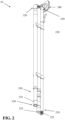
- FIG. 1 is a front perspective view of a non-limiting, exemplary extension pole in accordance with one non-limiting implementation of the present disclosure, showing the extension pole in a fully collapsed configuration.
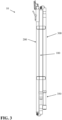
- FIG. 2 is a rear perspective view of the extension pole of FIG. 1 .
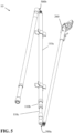
- FIG. 3 is a side view of the extension pole of FIG. 1 .
- FIG. 4 is a front perspective view of the extension pole of FIG. 1 , showing the extension pole in a partially open and/or closed configuration.
- FIG. 5 is a rear perspective view of the extension pole of FIG. 4 .
- FIG. 6 is a side view of the extension pole of FIG. 4 .
- FIG. 7 depicts the extension pole of FIG. 1 in a partially extended configuration.
- FIG. 8 depicts the extension pole of FIG. 1 in a fully extended configuration.
- FIGS. 9A-9C depict the transition of the extension pole of FIG. 1 from the fully collapsed configuration to the fully extended configuration, wherein FIG. 9A depicts the disclosed extension pole in the fully collapsed configuration, wherein FIG. 9B depicts the disclosed extension pole in the partially extended configuration, and wherein FIG. 9C depicts the disclosed extension pole in the fully extended configuration.
- FIG. 11A depicts the compressible portion of FIG. 10A in a fully compressed configuration, and wherein FIG. 11B is a partial cross-sectional view of FIG. 11A .
- FIG. 12 depicts an exemplary, non-limiting partition system comprising the extension pole of FIG. 1 .
- an extension pole 10 that is configured for use within a partition system 75 (see FIG. 12 ), and wherein the extension pole 10 includes a main pole section 100, a removable top pole section 200, and a removable bottom pole section 300.
- the main pole section 100 is formed of a plurality of pole sections 11 0a, 11 0b, 110c that are arranged in a telescoping configuration.
- Each of the pole sections 110a, 110b, 110c have a tubular body 112a, 112b, 112c, respectively.
- each of the pole sections 110a, 110b, 110c is selected so that the pole sections 110a, 110b, 110c can be telescopically fitted together, and so that the pole section 110a, 110b, 110c can be telescopically extended and collapsed.
- the main pole section 100 section is configured to provide most (e.g., 80-99.99% and all values and ranges therebetween) or all of the height/longitudinal length adjustment to the collapsible and extendable extension pole 10, as illustrated in FIGS. 9A-9C .
- the pole sections 110a, 110b, 110c can optionally include a grip and/or grip surface 140 (e.g., rough surface, grooved surface, ribbed surface, polymer- or rubber-coated surface, etc.) to facilitate in the gripping of one or more of the pole sections 110a, 110b, 110c.
- the main pole section 100 further includes a first end 120 and a second end 130, wherein a female fitting 125 is formed at the first end 120 and a male fitting 135 is formed at the second end 130.
- the main pole section 100 typically includes a securing arrangement (e.g., e.g., clamp, rivet, pin, adhesive, screw, nail, bracket, clip, twist lock, push button spring, internal twist action telescopic pole locking system, internal push button telescopic pole locking system, external twist action telescopic pole clamping system, clamp arrangement, cable or pin locking arrangement, etc.) that is configured to releasably secure the pole sections 110a, 110b, 110c in position relative to one another after the desired positioning of the pole sections 110a, 110b, 110c relative to one another (e.g., the extending of the pole sections 110a, 110b, 110c relative to one another) is obtained.
- a securing arrangement e.g., clamp, rivet, pin, adhesive, screw, nail, bracket, clip, twist lock, push button spring, internal twist action telescopic pole locking system, internal push button telescopic pole locking system, external twist action telescopic pole clamping system, clamp arrangement, cable or pin locking arrangement, etc.
- the main pole section 100 optionally includes at least one pole clip 150 that is configured to releasably connect the top pole section 200 and/or bottom pole section 300 to the main pole section 100 when the extension pole 10 is in a partially or fully collapsed configuration. As illustrated in FIGS. 1-3 , the main pole section 100 is in the fully collapsed position which the top pole section 200 and bottom pole section 300 are releasably connected to the main pole section 100; however, it will be appreciated that the top pole section 200 and/or bottom pole section 300 can be releasably connected to the main pole section 100 while the main pole section 100 is not in the fully collapsed position.
- the pole clip 150 facilitates in maintaining a compact orientation when the collapsible and extendable extension pole 10 is in the compact and collapsed orientation, as illustrated in FIGS. 1-3 .
- the at least one pole clip 150 can also or alternatively be positioned on the top pole section 200 and/or the bottom pole section 300.
- the material used to form the at least one pole clip 150 is non-limiting (e.g., plastic, metal, composite material, etc.).
- the pole clip 150 includes a flexible or bendable bracket that can releasably fit about a portion or all of the main pole section 100.
- the removable top pole section 200 includes a tubular body 210 that has the same shape and circular cross-sectional size as the first end 120 of the main pole section 100.
- the top pole section 200 includes a first end 220 and a second end 230, wherein a male fitting 225 is formed at the first end 220.
- a grip pad 240 is pivotally coupled to the second end 230.
- Upper surface 242 of the grip pad 240 can include a smooth surface, a non-smooth surface, and/or an adhesive surface to a) facilitate in forming a non-slip or reduced slip interface between the upper surface 242 of the grip pad 240 and a ceiling, wall, or other structure with which the upper surface 242 engages when the collapsible and extendable extension pole 10 is installed, and/or b) facilitate in forming a non-slip or reduced slip interface between the upper surface 242 of the grip pad 240 and the barrier/partition material 50 when the collapsible and extendable extension pole 10 is installed (see for example FIG. 12 ).
- the grip pad 240 has a generally square or rectangular shape and formed of a plastic or rubber material.
- the top pole section 200 further includes a barrier material clip 250 that is connected thereto by a sleeve clamp arrangement 260.
- the barrier material clip 250 is configured to removably connect the barrier material 50 to the removable top pole section 200 (see for example FIG. 12 ).
- the barrier material clip 250 can include a spring-loaded pivoting arm that biases the pivoting arm in the closed position.
- the barrier material clip 250 can have other and/or additional configurations.
- the material used to make the barrier material clip 250 is non-limiting (e.g., plastic, metal, etc.).
- the barrier material clip 250 can be connected to the removable top pole section by any number of arrangements (e.g., adhesive, screw, nail, pin, rivet, clamp, bracket, clip, etc.). Many types of barrier material connection arrangements that can be used are illustrated and described in the prior art references that are incorporated herein.
- the male fitting 225 that is formed on top pole section 200 is configured to engage the female fitting 125 on the main pole section 100 to form a releasable connection between the removable top pole section 200 and the main pole section 100.
- the male fitting 225 allows the removable top pole section 200 to be connected and disconnected from the main pole section 100.
- the male fitting 225 has a size and shape that facilitates in the insertion of the male fitting 225 into the female fitting 125.
- the male fitting 225 can optionally include a tapered region that is configured to further facilitate in the insertion of the male fitting 225 into the female fitting 125 of the main pole section 100.
- the first end 120 of the main pole section 100 could optionally include a male fitting (similar to that of the male fitting 225) such that the male fitting would be inserted into a female fitting (similar to the female fitting 125) formed on the first end 220 of the top pole section 200 (e.g., a reverse configuration to what is illustrated in FIGS. 1-8 ).
- a male fitting similar to that of the male fitting 225
- a female fitting similar to the female fitting 125
- the shape, size, and materials used to form the male fitting 225 are non-limiting.
- a first tether 500a forms a connection between the removable top pole section 200 and main pole section 100.
- the first tether 500a can be formed of a cord, elastic cord, wire, strap, etc.
- the material used to form the first tether 500a is non-limiting (e.g. metal, plastic, composite material, elastic material, etc.).
- the first tether 500a can be permanently or removably connected to the removable top pole section 200 and/or main pole section 100.
- the first tether 500a is optionally formed of an elastic material that is permanently connected to the removable top pole section 200 and main pole section 100.
- the elastic material, when used, and length of the first tether 500a can be selected to cause the first end 220 of the removable top pole section 200 to be drawn toward the first end 120 of the main pole section 100 when the removable top pole section 200 and the main pole section 100 are positioned generally parallel to one another, as illustrated in FIGS. 1-3 ; however, this is not required.
- Such drawing action facilitates in maintaining a compact orientation of the removable top pole section 200 relative to the main pole section 100 when the collapsible and extendable extension pole 10 is in the compact and collapsed orientation, as illustrated in FIGS. 1-3 .
- a spring arrangement could be connected to one or both ends of the first tether 500a to create the drawing together effect as an alternative or in additional use of an elastic material for the first tether 500a.
- the first tether 500a can also be configured to draw together the removable top pole section 200 relative to the main pole section 100 when the removable top pole section 200 is removably connected to the main pole section 100.
- the tether can be formed of a non-elastic material.
- the removable bottom pole section 300 includes a tubular body 310 that has the same shape and circular cross-sectional size as the second end 130 of the main pole section 100.
- the removable bottom pole section 300 includes a first end 320, a second end 330, and a compressible portion 350.
- the first end 320 includes a female fitting 325 formed thereon that is configured to receive the male fitting 135 of the main pole section 100 and form a releasable connection between the removable bottom pole section 300 and the main pole section 100.
- the female fitting 325 allows the removable bottom pole section 300 to be connected and disconnected from the main pole section 100.
- the female fitting 325 has a size and shape that facilitates in the insertion of the male fitting 135 into the female fitting 325.
- the male fitting 135 can optionally include tapered region that is configured to further facilitate in the insertion of the male fitting 135 into the female fitting 325.
- the first end 320 of the bottom pole section 300 could optionally include a male fitting (similar to the male fitting 135) such that the male fitting would be inserted into a female fitting (similar to the female fitting 325) formed on the second end 130 of the main pole section 100 (e.g., a reverse configuration to what is illustrated in FIGS. 1-8 ).
- the shape, size, and materials used to form the male fitting 135 are non-limiting.
- a second tether 500b forms a connection between the removable bottom pole section 300 and main pole section 100.
- the second tether 500b can be formed of a cord, elastic cord, wire, strap, etc.
- the material used to form the second tether 500b is non-limiting (e.g. metal, plastic, composite material, elastic material, etc.).
- the second tether 500b can be permanently or removably connected to the removable bottom pole section 300 and/or main pole section 100.
- the second tether 500b is optionally formed of an elastic material that is permanently connected to the removable bottom pole section 300 and main pole section 100.
- the elastic material, when used, and length of the second tether 500b can be selected to cause the first end 320 of the removable bottom pole section 300 to be drawn toward the second end 130 of the main pole section 100 when the removable bottom pole section 300 and the main pole section 100 are positioned generally parallel to one another, as illustrated in FIGS. 1-3 .
- Such drawing action facilitates in maintaining a compact orientation of the removable bottom pole section 300 relative to the main pole section 100 when the collapsible and extendable extension pole 10 is in the compact and collapsed orientation, as illustrated in FIGS. 1-3 .
- a spring arrangement could be connected to one or both ends of the second tether 500b to create the drawing together effect as an alternative or in additional use of an elastic material for second tether 500b.
- the second tether 500b can also be configured to optionally draw together the removable bottom pole section 300 relative to the main pole section 100 when the removable bottom pole section 300 is removably connected to the main pole section 100.
- the tether can be formed of a non-elastic material.
- the bottom pole section 300 further includes a compressible portion 350 that is configured to be biased downwardly (e.g., biased in an extended position).
- the compressible portion 350 is configured to partially or fully compress when the removable bottom pole section 300 or the optional non-slip foot 335 on the second end 330 of the removable bottom pole section 300 engages a floor or other structure during the installation of the collapsible and extendable extension pole 10.
- Such compression portion 350 facilitates in securing the collapsible and extendable extension pole 10 in position during installation of the collapsible and extendable extension pole 10.
- the compressible portion 350 comprises a spring or similar type of biasing member (e.g., spring) 352, a rod 354 that is telescopically received in the tubular body 310, and a stop 356.
- the spring 352 is disposed between the rod 354 and the stop 356.
- the tubular body 310 can alternatively be configured to be telescopically received in the rod 354 of the compressible portion 350.
- the spring or similar type of biasing member 352 is configured to compress 0.5-10 in. (1.3 cm - 25 cm) (and all values and ranges therebetween) such that the longitudinal length of the removable bottom pole section 300 has a variable longitudinal length of up to 10 in. (25 cm) (0.001-10 in. (0.00254 cm - 25.4 cm) and all values and ranges therebetween) due to the compression of the compressible portion 350.
- the removable bottom pole section 300 had a longitudinal length of 42 inches (107 cm) when the compressible portion 350 was not in a compressed state, the removable bottom pole section 300 would have a longitudinal length of 38 inches (97 cm) when the spring 352 of the compressible portion 350 was compressed about 4 inches (10 cm).
- the removable top pole section 200 could optionally include a compression portion similar to the compression portion 350 described and illustrated with respect to the bottom pole section 300, the difference being that the compression portion in the top pole section 200 would be biased upwardly.
- a non-slip foot 335 can optionally be used that is coupled to the rod 354.
- the non-slip foot 335 is generally formed of a non-slip material (e.g., plastic, rubber, etc.). The size and shape of the non-slip foot 335 are non-limiting.
- the non-slip foot 335 is configured to inhibit or prevent movement or slipping of the removable bottom pole section 300 on a floor or other surface once the collapsible and extendable extension pole 10 has been installed.
- the bottom pole section 300 optionally includes one or more grips 340 (e.g., rough surface, grooved surface, ribbed surface, polymer- or rubber-coated surface, etc.) to facilitate in the gripping of the removable bottom pole section 300.
- the disclosed main pole section 100 can be formed of a single pole section, or can be formed of a plurality of telescoping sections as disclosed in the Figures 1-12 . It can be appreciated that the disclosed main pole section 100 can be formed of two telescoping pole sections or more than three telescoping sections (e.g., 4-10 telescoping pole sections and all values and ranges therebetween).
- the length of each of the pole sections 110a, 110b, 110c can be 0.5-8 feet (0.15 m - 2.44 m) (and all values and ranges therebetween).
- the length of each of the pole sections 110a, 110b, 110c of the main pole body section 100 is 2-5 feet (0.6 m - 1.5 m), and typically 2.5-4 feet (0.8 m - 1.2 m).
- the pole sections 110a, 110b, 110c can have the same or a different longitudinal length.
- the length of the pole sections can be the same or different.
- pole sections 110a, 110b, 110c can optionally include a releasable locking arrangement that allows a user to releasably lock two pole sections relative to one another in position once the two telescoping poles have been expanded or contracted in a desired position with respect to one another.
- a releasable locking arrangement that allows a user to releasably lock two pole sections relative to one another in position once the two telescoping poles have been expanded or contracted in a desired position with respect to one another.
- the disclosed main pole section 100, top pole section 200, and bottom pole section 300 include tubular shaped bodies; however, it can be appreciated that the bodies of the main, top, and bottom pole sections 100, 200, 300 can have a non-circular shape (e.g., square, rectangular, polygonal, oval, etc.).
- the disclosed extension pole can be formed of: (i) top pole section 200 releasably coupled to main pole section 100; (ii) bottom pole section 300 releasably coupled to main pole section 100; or (iii) top pole section 200 and bottom pole section 300 releasably coupled to main pole section 100, as illustrated in Figures 1-12 . It is also to be appreciated that any of the above mentioned components of the extension pole 10 can be used with any of the possible extension pole configurations mentioned in this paragraph.
- the extension pole is formed only of top pole section 200 releasably coupled to main pole section 100
- the second end 130 of main pole section 100 could be configured to include a compression portion similar to compression portion 350 and/or a non-slip foot similar to foot 335.
- the disclosed collapsible and extendable extension pole 10 is configured to have a collapsible configuration for easy storage or transport and/or have a size that is small enough for shelf display of the collapsible and extendable extension pole 10 in the collapsed state.
- Prior art extension poles that are used for rooms having 8-15 ft. (2.4 m - 4.6 m) ceilings are typically 5-8 in. (13 cm - 20 cm) in length in a collapsible state. As such, these long poles can be difficult to transport and store.
- extension pole 10 is configured to have a significantly smaller collapsible profile as compared to standard extension poles.
- the disclosed main pole section is typically formed of 2-4 telescopically arranged pole sections that enables the main pole body section to have an adjustable longitudinal length.
- each of the disclosed pole sections of the main pole body section have a maximum longitudinal length of no more than 48 inches (122 cm), and typically no more than 40 inches (102 cm) (e.g., 20-40 in.) (51-102 cm).
- the disclosed main pole body section in the collapsed state has a maximum longitudinal length of no more than 48 inches (122 cm), and typically no more than 40 inches (102 cm).
- the removable top pole section 200 and a removable bottom pole section 300 is equal to or less than the longitudinal length the main pole section 100 in the collapsed state (see FIGS. 1-3 ).
- the longitudinal length of the collapsible and extendable extension pole 10 in the collapsed and stored state is no more than 48 inches (122 cm) (e.g., 20-48 inches (51-122 cm) and all values and ranges therebetween), and typically no more than 40 inches (102 cm).
- the collapsible and extendable extension pole 10 has a) a maximum longitudinal length in the collapsed and stored state of 48 inches (122 cm) (e.g., 25-48 in. (64 cm - 122 cm) and all values and ranges therebetween), b) a main pole section 100 that is formed of a plurality of pole sections 110a, 110b, 110c that are telescopically connected together, and wherein the maximum longitudinal length of each pole section 110a, 110b, 110c is 20-47 inches (51 cm - 119 cm) (and all values and ranges therebetween), and wherein the maximum longitudinal length of the main pole section 100 in the collapsed position is 48 inches (122 cm) (e.g., 25-48 in.
- each of the removable top pole section 200 and the removable bottom pole section 300 have a longitudinal length that is less than the maximum longitudinal length of the main pole section 100 in the collapsed position and wherein the maximum longitudinal length of the collapsible and extendable extension pole 10 in the fully assembled and expanded state is 369 inches (937 cm) (e.g., 70-369 in. (178 cm - 937 cm) and all values and ranges therebetween).
- the collapsible and extendable extension pole 10 has a) a maximum longitudinal length in the collapsed and stored state of 36 inches (91 cm), b) a main pole section 100 that is formed of pole section 110a, 110b, 110c that are telescopically connected together, and wherein the maximum longitudinal length of each pole section 110a, 110b, 110c is 20-35 inches, and wherein the maximum longitudinal length of the main pole section 100 in the collapsed position is 36 inches (91 cm), and wherein the main pole section 100 is expandable from 20-104 inches (51 cm - 264 cm) (and all values and ranges therebetween), and c) a removable top pole section 200 and a removable bottom pole section 300 that are removably connectable to the main pole section 100, and wherein each of the removable top pole section 200 and the removable bottom pole section 300 have a longitudinal length that is less than the maximum longitudinal length of the main pole section 100 in the collapsed position, and wherein the maximum longitudinal length of the collapsible and extendable extension
- the size of the disclosed collapsible and extendable extension pole in the collapsed and stored state in accordance with the present disclosure allows for a) easy storage of the collapsible and extendable extension pole collapsible and extendable extension pole when in the stored state, b) convenient transport of the collapsible and extendable extension pole due to the smaller size in the stored state, c) allows for the collapsible and extendable extension pole to be placed on a standard shelf for retain sale when in the stored state, and d) a carrying case can be used to place the collapsible and extendable extension pole in the carrying case when the collapsible and extendable extension pole is in the stored state.
- the collapsible and extendable extension pole includes a removable bottom pole section.
- the removable bottom section can include a) an optional bottom male fitting, b) an optional bottom tether arrangement, c) an optional outer gripping surface, d) an optional compressible bottom portion, e) an optional non-slip foot arrangement, and/or f) an optional pole clip arrangement. As illustrated in FIGS.
- the removable bottom pole section has a tubular-shaped body that has the same shape and circular cross-sectional size as the bottom pole section of the main pole section; however, it can be appreciated that the body of the removable bottom pole section can have a non-circular shape (e.g., square, rectangular, polygonal, oval, etc.) and/or can have a larger or smaller cross-sectional shape as compared to the bottom pole section of the main pole section.
- the longitudinal length of the removable bottom pole section can be longer, the same, or shorter than a longitudinal length of the main pole section when in the fully collapsed position or when the main pole section is formed of a single pole section. As illustrated in FIG.
- the longitudinal length of the removable bottom pole section is shorter than the longitudinal length of the main pole section when in the fully collapsed position.
- the removable bottom pole section includes a bottom male fitting.
- the bottom male fitting is configured to form a releasable connection between the top portion of the removable bottom pole section and the bottom portion of the main pole section so that a releasable connection is formed between the removable bottom pole section and the main pole section.
- the bottom male fitting allows the removable bottom pole section to be connected and disconnected from the main pole section.
- the bottom male fitting has a size and shape to facilitate in the insertion of the bottom male fitting into the opening in the bottom of the main pole section.
- the bottom male fitting can optionally include a tapered region that is configured to further facilitate in the insertion of the bottom male fitting into the opening in the bottom of the main pole section.
- the bottom of the main pole section can optionally include the bottom male fitting such that the bottom male fitting is configured to be inserted into an opening in the top of the removable bottom pole section (e.g., a reverse configuration to what is illustrated in FIG. 1 ).
- the shape, size, and materials used to form the bottom male fitting are non-limiting.
- the bottom male fitting can optionally be permanently secured to the removable bottom pole section. Further features of the bottom male fitting are described in FIG. 2 .
- the removable bottom pole section includes a bottom tether arrangement.
- the bottom tether arrangement forms a connection between the removable bottom pole section and main pole section.
- the bottom tether arrangement can be formed of a cord, elastic cord, wire, strap, etc.
- the material used to form the bottom tether arrangement is non-limiting (e.g. metal, plastic, composite material, elastic material, etc.).
- the bottom tether arrangement can be permanently or removably connected to the removable bottom pole section and/or main pole section. As illustrated in FIGS. 1-2 , the bottom tether arrangement is formed of an elastic material that is permanently connected to the removable bottom pole section and main pole section.
- the elastic material and length of the bottom tether arrangement can be selected to cause the top of the removable bottom pole section to be drawn toward the bottom of the main pole section when the removable bottom pole section and the main pole section are positioned generally parallel to one another as illustrated in FIG. 1 .
- Such drawing action facilitates in maintaining a compact orientation of the removable bottom pole section relative to the main pole section when the collapsible and extendable extension pole is in the compact and collapsed orientation as illustrated in FIG. 1 .
- a spring arrangement could be connected to one or both ends of the tether to create the drawing together effect as an alternative or additional use of an elastic material for the tether.
- the tether can also be configured to draw together the removable bottom pole section relative to the main pole section when the removable bottom pole section is removably connected to the mail pole section. Further details of the tether are described in FIG. 2 .
- the removable bottom pole section includes an outer gripping surface to facilitate in the handling/gripping of the removable bottom pole section.
- the type of gripping surface is non-limiting (e.g., rough surface, grooved surface, ribbed surface, polymer- or rubber-coated surface, etc.).
- the removable bottom pole section includes a main bottom body and a compressible bottom portion. The compressible bottom portion is configured to be biased downwardly. Such biasing can be by a spring arrangement or other type of biasing arrangement.
- the biasing arrangement is a spring arrangement that is configured to compress 0.5-10 in. (and all values and ranges therebetween) such that the longitudinal length of the removable bottom pole section has a variable longitudinal length of up to 10 in. (0.001-10 in. and all values and ranges therebetween) due to the compression of the compressible bottom portion.
- the removable bottom pole section had a longitudinal length of 42 in. when the compressible bottom portion was not in a compressed state, the removable bottom pole section would have a longitudinal length of 38 in. when the spring of the compressible bottom portion was compressed about 4 in.
- the removable bottom pole section is configured to partially or fully compress when the bottom of the removable bottom pole section or the optional non-slip foot arrangement on the bottom portion of the removable bottom pole section engages a floor or other structure during the installation of the collapsible and extendable extension pole.
- Such compression arrangement facilitates in securing the collapsible and extendable extension pole in position during installation of the collapsible and extendable extension pole.
- the optional non-slip foot arrangement can optionally be connected to the bottom end portion of the compressible bottom portion.
- the compressible bottom portion is a tubular member that is telescopically received in a tubular portion of the main bottom body. The size, length, and shape of the compressible bottom portion and the main bottom body are non-limiting.
- the removable bottom pole section includes a pole clip arrangement.
- the pole clip arrangement is used to releasably connect the body of the removable bottom pole section to the main pole section when the removable bottom pole section and the main pole section are position generally parallel to one another as illustrated in FIG. 1 .
- Such releasable connection by the pole clip arrangement facilitates in maintaining a compact orientation of the removable bottom pole section relative to the main pole section when the collapsible and extendable extension pole is in the compact and collapsed orientation as illustrated in FIG. 1 .
- the pole clip arrangement can also or alternatively be positioned on the main pole section.
- the material used to form the pole clip arrangement is non-limiting (e.g., plastic, metal, composite material, etc.). As illustrated in FIG.
- the pole clip arrangement includes a flexible or bendable bracket that can releasably fit about a portion or all of the body of the main pole section.
- the pole clip arrangement can have other configurations.
- the pole clip arrangement is configured to connect to the top portion of the main pole section; however, this is not required.
- more than one pole clip arrangement can be positioned on the removable bottom pole section and/or main pole section. Further details about the pole clips are described in FIG. 2 .
- the collapsible and extendable extension pole is configured to have a collapsible configuration for easy storage or transport and/or have a size that is small enough for shelf display of the collapsible and extendable extension pole in the collapsed state.
- Prior art extension poles that are used for rooms having 8-15 ft. (2.4 m - 4.6 m) ceilings are typically 5-8 in. (13 cm - 20 cm) in length in a collapsible state. As such, these long poles can be difficult to transport and store.
- the collapsible and extendable extension pole is configured to have a significantly smaller collapsible profile as compared to standard extension poles.
- the collapsible and extendable extension pole includes a main pole body section and one or both of a removable top pole section and a removable bottom pole section.
- the main pole body section is typically formed of 2-4 telescopically arranged pole sections that enables the main pole body section to have an adjustable longitudinal length.
- each of the pole sections of the main pole body section have a maximum longitudinal length of no more than 48 in. (122 cm), and typically no more than 40 inches (102 cm) (e.g., 20-40 in. (51 cm - 102 cm)).
- the main pole body section in the collapsed state has a maximum longitudinal length of no more than 48 inches (122 cm), and typically no more than 40 in (102 cm).
- the longitudinal length of the removable top pole section and a removable bottom pole section is equal to or less than the longitudinal length the main pole body section in the collapsed state.
- the longitudinal length of the collapsible and extendable extension pole in the collapsed and stored state is no more than 48 inches (122 cm) (e.g., 20-48 inches (51 - 122 cm) and all values and ranges therebetween), and typically no more than 40 inches (102 cm).
- the collapsible and extendable extension pole has a) a maximum longitudinal length in the collapsed and stored state of 48 inches (122 cm) (e.g., 25-48 in.
- a main body section that is formed of a plurality of pole sections (e.g., 2-6 pole sections and all values and ranges therebetween) that are telescopically connected together, and wherein the maximum longitudinal length of each pole section is 20-47 in. (51 - 102 cm) (and all values and ranges therebetween), and wherein the maximum longitudinal length of the a main body section in the collapsed position is 48 in. (122 cm) (e.g., 25-48 in.
- each of the removable top pole section and the removable bottom pole section have a longitudinal length that is less than the maximum longitudinal length of the a main body section in the collapsed position and wherein the maximum longitudinal length of the collapsible and extendable extension pole in the fully assembled and expanded state is 369 in. (937 cm) (e.g., 70-369 in. (178 - 937 cm) and all values and ranges therebetween).
- the collapsible and extendable extension pole has a) a maximum longitudinal length in the collapsed and stored state of 36 inches, b) a main body section that is formed of 2-3 pole sections that are telescopically connected together, and wherein the maximum longitudinal length of each pole section is 20-35 in. (51 cm - 99 cm), and wherein the maximum longitudinal length of the a main body section in the collapsed position is 36 in. (91 cm), and wherein the main body section is expandable from 20-104 in.
- each of the removable top pole section and the removable bottom pole section have a longitudinal length that is less than the maximum longitudinal length of the a main body section in the collapsed position, and wherein the maximum longitudinal length of the collapsible and extendable extension pole in the fully assembled and expanded state is 174 in. (442 cm) (e.g., 70-174 in. (178 - 442 cm) and all values and ranges therebetween).
- the size of the collapsible and extendable extension pole in the collapsed and stored state in accordance with the present disclosure allows for a) easy storage of the collapsible and extendable extension pole collapsible and extendable extension pole when in the stored state, b) convenient transport of the collapsible and extendable extension pole due to the smaller size in the stored state, c) allows for the collapsible and extendable extension pole to be placed on a standard shelf for retain sale when in the stored state, and d) a carrying case can be used to place the collapsible and extendable extension pole in the carrying case when the collapsible and extendable extension pole is in the stored state.
Landscapes
- Engineering & Computer Science (AREA)
- Architecture (AREA)
- Civil Engineering (AREA)
- Structural Engineering (AREA)
- Mechanical Engineering (AREA)
- Clamps And Clips (AREA)
- Refuge Islands, Traffic Blockers, Or Guard Fence (AREA)
- Tents Or Canopies (AREA)
Applications Claiming Priority (1)
| Application Number | Priority Date | Filing Date | Title |
|---|---|---|---|
| US202363604551P | 2023-11-30 | 2023-11-30 |
Publications (1)
| Publication Number | Publication Date |
|---|---|
| EP4563770A1 true EP4563770A1 (de) | 2025-06-04 |
Family
ID=93742912
Family Applications (1)
| Application Number | Title | Priority Date | Filing Date |
|---|---|---|---|
| EP24216496.0A Pending EP4563770A1 (de) | 2023-11-30 | 2024-11-29 | Verlängerungsmast |
Country Status (3)
| Country | Link |
|---|---|
| US (1) | US20250179827A1 (de) |
| EP (1) | EP4563770A1 (de) |
| GB (1) | GB2638521A (de) |
Citations (12)
| Publication number | Priority date | Publication date | Assignee | Title |
|---|---|---|---|---|
| US4708189A (en) | 1985-02-05 | 1987-11-24 | Ward Alec D | Screen |
| US4794974A (en) | 1986-03-06 | 1989-01-03 | Melino Charles E | Interior curtain wall |
| US5308280A (en) | 1992-12-14 | 1994-05-03 | Curtain Buddy Corp. | Method and apparatus for supporting ventilation curtains in coal mines |
| US5924469A (en) | 1996-10-29 | 1999-07-20 | Zipwall, Llc | Partition mount |
| DE20211381U1 (de) * | 2002-07-23 | 2003-12-04 | Lenhart, Klaus | Faltbarer Stock |
| GB2458628A (en) * | 2007-12-18 | 2009-09-30 | Difei Wang | Airlock tent system |
| US7658219B2 (en) | 2004-05-10 | 2010-02-09 | Zipwall, Llc | Partition mount with integrated plunger assembly |
| WO2011048028A1 (en) * | 2009-10-21 | 2011-04-28 | Conall Stokes | A walking aid |
| WO2018154107A1 (de) * | 2017-02-27 | 2018-08-30 | Wolfgang Held | Stange für geräte |
| US10781597B2 (en) | 2015-12-28 | 2020-09-22 | Zipwall, Llc | Self-closing entryway partition |
| US20220081963A1 (en) | 2018-12-06 | 2022-03-17 | Zipwall, Llc | Self-closing entryway for door-frame |
| EP4099866B1 (de) * | 2020-02-07 | 2023-10-04 | Lekisport AG | Faltstock |
Family Cites Families (3)
| Publication number | Priority date | Publication date | Assignee | Title |
|---|---|---|---|---|
| CN201502214U (zh) * | 2009-07-30 | 2010-06-09 | 金祚献 | 帐篷杆蚊帐杆杆组结构 |
| KR101181722B1 (ko) * | 2012-02-07 | 2012-09-19 | 오성듀랄루민(주) | 분리가 원활한 텐트용 폴 |
| KR101581366B1 (ko) * | 2014-06-17 | 2015-12-31 | (주)라이브플렉스 | 텐트용 폴 |
-
2024
- 2024-11-08 GB GB2416483.2A patent/GB2638521A/en active Pending
- 2024-11-22 US US18/957,067 patent/US20250179827A1/en active Pending
- 2024-11-29 EP EP24216496.0A patent/EP4563770A1/de active Pending
Patent Citations (16)
| Publication number | Priority date | Publication date | Assignee | Title |
|---|---|---|---|---|
| US4708189A (en) | 1985-02-05 | 1987-11-24 | Ward Alec D | Screen |
| US4794974A (en) | 1986-03-06 | 1989-01-03 | Melino Charles E | Interior curtain wall |
| US5308280A (en) | 1992-12-14 | 1994-05-03 | Curtain Buddy Corp. | Method and apparatus for supporting ventilation curtains in coal mines |
| US5924469A (en) | 1996-10-29 | 1999-07-20 | Zipwall, Llc | Partition mount |
| DE20211381U1 (de) * | 2002-07-23 | 2003-12-04 | Lenhart, Klaus | Faltbarer Stock |
| US8857499B2 (en) | 2004-05-10 | 2014-10-14 | Zipwall Llc | Partition mount with integrated plunger assembly |
| US7658219B2 (en) | 2004-05-10 | 2010-02-09 | Zipwall, Llc | Partition mount with integrated plunger assembly |
| US10689865B2 (en) | 2004-05-10 | 2020-06-23 | Zipwall, Llc | Partition mount with integrated plunger assembly |
| US11530542B2 (en) | 2004-05-10 | 2022-12-20 | Zipwall, Llc. | Partition mount with integrated plunger assembly |
| GB2458628A (en) * | 2007-12-18 | 2009-09-30 | Difei Wang | Airlock tent system |
| WO2011048028A1 (en) * | 2009-10-21 | 2011-04-28 | Conall Stokes | A walking aid |
| US10781597B2 (en) | 2015-12-28 | 2020-09-22 | Zipwall, Llc | Self-closing entryway partition |
| US20210404198A1 (en) | 2015-12-28 | 2021-12-30 | Zipwall, Llc. | Self-closing entryway partition |
| WO2018154107A1 (de) * | 2017-02-27 | 2018-08-30 | Wolfgang Held | Stange für geräte |
| US20220081963A1 (en) | 2018-12-06 | 2022-03-17 | Zipwall, Llc | Self-closing entryway for door-frame |
| EP4099866B1 (de) * | 2020-02-07 | 2023-10-04 | Lekisport AG | Faltstock |
Also Published As
| Publication number | Publication date |
|---|---|
| GB202416483D0 (en) | 2024-12-25 |
| GB2638521A (en) | 2025-08-27 |
| US20250179827A1 (en) | 2025-06-05 |
Similar Documents
| Publication | Publication Date | Title |
|---|---|---|
| US8286926B1 (en) | Collapsible leg assembly | |
| US6948591B2 (en) | Support apparatus or accessory for a ladder | |
| US6519809B2 (en) | Gutter cleaner | |
| US5337996A (en) | Portable easel system | |
| US20020011316A1 (en) | Partition mount | |
| US20180356032A1 (en) | Mount | |
| WO2007130944A2 (en) | Accessory mounting systems and mounting methods thereof | |
| US8381749B1 (en) | Adjustable hunting blind | |
| US20210155376A1 (en) | Systems and Methods for Attaching a Container | |
| US4687154A (en) | Device for handling and storage of extension cords and the like | |
| US10392817B2 (en) | Panel installation appartus | |
| AU2007284742A1 (en) | Foldable CPAP breathing hose support boom | |
| EP4563770A1 (de) | Verlängerungsmast | |
| US6257418B1 (en) | Retractable display apparatus | |
| US12157511B2 (en) | Folding utility cart accessory device | |
| CA3255985A1 (en) | Extension pole | |
| US20170127809A1 (en) | A camping table | |
| CA2826804C (en) | Support apparatus and extendable pole accessory for supporting crown moulding or other elongated workpieces on a wall surface | |
| US20230017385A1 (en) | Collapsible Platform Assembly | |
| US6561450B1 (en) | Fire hose winder | |
| US20120074276A1 (en) | Adjustable, retractable ceiling and wall hanging system | |
| US7725969B1 (en) | Climbing and rappelling accessory and method | |
| US20250194762A1 (en) | Portable umbrella stand | |
| US20100108850A1 (en) | Stand for supporting a tree | |
| WO2017151527A1 (en) | A ladder support device and a method for securing a ladder to a base |
Legal Events
| Date | Code | Title | Description |
|---|---|---|---|
| PUAI | Public reference made under article 153(3) epc to a published international application that has entered the european phase |
Free format text: ORIGINAL CODE: 0009012 |
|
| STAA | Information on the status of an ep patent application or granted ep patent |
Free format text: STATUS: THE APPLICATION HAS BEEN PUBLISHED |
|
| AK | Designated contracting states |
Kind code of ref document: A1 Designated state(s): AL AT BE BG CH CY CZ DE DK EE ES FI FR GB GR HR HU IE IS IT LI LT LU LV MC ME MK MT NL NO PL PT RO RS SE SI SK SM TR |
|
| STAA | Information on the status of an ep patent application or granted ep patent |
Free format text: STATUS: REQUEST FOR EXAMINATION WAS MADE |
|
| 17P | Request for examination filed |
Effective date: 20251204 |
|
| RIN1 | Information on inventor provided before grant (corrected) |
Inventor name: HANSON, MATTHEW Inventor name: MCDONOUGH, TIMOTHY JAMES Inventor name: PRATHER, REBECCA JOELLE |
|
| STAA | Information on the status of an ep patent application or granted ep patent |
Free format text: STATUS: EXAMINATION IS IN PROGRESS |