EP4563772A2 - Ferrure de porte - Google Patents
Ferrure de porte Download PDFInfo
- Publication number
- EP4563772A2 EP4563772A2 EP24203995.6A EP24203995A EP4563772A2 EP 4563772 A2 EP4563772 A2 EP 4563772A2 EP 24203995 A EP24203995 A EP 24203995A EP 4563772 A2 EP4563772 A2 EP 4563772A2
- Authority
- EP
- European Patent Office
- Prior art keywords
- door
- handle
- door handle
- fitting
- lock
- Prior art date
- Legal status (The legal status is an assumption and is not a legal conclusion. Google has not performed a legal analysis and makes no representation as to the accuracy of the status listed.)
- Pending
Links
Images


Classifications
-
- E—FIXED CONSTRUCTIONS
- E05—LOCKS; KEYS; WINDOW OR DOOR FITTINGS; SAFES
- E05B—LOCKS; ACCESSORIES THEREFOR; HANDCUFFS
- E05B13/00—Devices preventing the key or the handle or both from being used
- E05B13/002—Devices preventing the key or the handle or both from being used locking the handle
-
- E—FIXED CONSTRUCTIONS
- E05—LOCKS; KEYS; WINDOW OR DOOR FITTINGS; SAFES
- E05B—LOCKS; ACCESSORIES THEREFOR; HANDCUFFS
- E05B1/00—Knobs or handles for wings; Knobs, handles, or press buttons for locks or latches on wings
- E05B1/003—Handles pivoted about an axis perpendicular to the wing
-
- E—FIXED CONSTRUCTIONS
- E05—LOCKS; KEYS; WINDOW OR DOOR FITTINGS; SAFES
- E05B—LOCKS; ACCESSORIES THEREFOR; HANDCUFFS
- E05B1/00—Knobs or handles for wings; Knobs, handles, or press buttons for locks or latches on wings
- E05B1/0092—Moving otherwise than only rectilinearly or only rotatively
-
- E—FIXED CONSTRUCTIONS
- E05—LOCKS; KEYS; WINDOW OR DOOR FITTINGS; SAFES
- E05B—LOCKS; ACCESSORIES THEREFOR; HANDCUFFS
- E05B13/00—Devices preventing the key or the handle or both from being used
- E05B13/002—Devices preventing the key or the handle or both from being used locking the handle
- E05B13/004—Devices preventing the key or the handle or both from being used locking the handle by locking the spindle, follower, or the like
-
- E—FIXED CONSTRUCTIONS
- E05—LOCKS; KEYS; WINDOW OR DOOR FITTINGS; SAFES
- E05B—LOCKS; ACCESSORIES THEREFOR; HANDCUFFS
- E05B65/00—Locks or fastenings for special use
- E05B65/10—Locks or fastenings for special use for panic or emergency doors
- E05B65/1086—Locks with panic function, e.g. allowing opening from the inside without a ley even when locked from the outside
-
- E—FIXED CONSTRUCTIONS
- E05—LOCKS; KEYS; WINDOW OR DOOR FITTINGS; SAFES
- E05B—LOCKS; ACCESSORIES THEREFOR; HANDCUFFS
- E05B1/00—Knobs or handles for wings; Knobs, handles, or press buttons for locks or latches on wings
- E05B2001/0076—The handle having at least two operating positions, e.g. the bolt can be retracted by moving the handle either upwards or downwards
Definitions
- the present invention relates to a door fitting for a door with a door leaf, in particular for an interior door, comprising two manually operable actuating handles which are arranged on opposite sides of the door leaf, preferably substantially mirror-symmetrically to the door leaf, and are designed as an interior and exterior door handle.
- door handles – also colloquially referred to as doorknobs or door handles, and usually mechanically rotating levers with one arm, but can also be axially symmetrical or oval doorknobs, sometimes offset from the rotation axis – are attached to the door leaf via round or elongated mounting plates.
- the former are called handle rosettes, the latter are called escutcheons. These have openings for the handle (handle hole) and key (keyhole). Separate rosettes for keys are called key rosettes, and the entire assembly is called a door fitting.
- the latch in the box-shaped door lock is driven by a finger of a lock follower that rotates around the handle's axis of rotation, retracting the (snap) latch when the handle is operated.
- the lock follower has a – usually square – cutout in its axis of rotation, through which a (square) pin of the same cross-section extends, both ends of which engage with the equally square blind holes in the door handle pair. This pin is held in its horizontal starting position by a "hard” so-called lock spring, which engages the circumference of the lock follower.
- the lock follower usually has a rotation stop located in the lock case that opposes the direction of rotation of the handle pair.
- the "levers" can usually only be pushed downwards and cannot be rotated upwards beyond their horizontal starting position!
- the lock follower is provided with mirror-symmetrical circular cylindrical shoulders on both sides, arranged coaxially to the follower axis and pivoted in corresponding holes in the two so-called lock covers of the usually box-shaped door lock.
- the pivot bearing of the lock follower in the lock case is mechanically a so-called (mirror-symmetrical) support bearing.
- a common door lock has a lock bolt which - in order to lock the door - can be extended and retracted by turning the door key and engages and disengages with the corresponding opening in the strike plate.
- door locks were designed as so-called box locks, which were placed on the door leaf. Therefore, they are also known as "surface locks,” which can still be found today, for example, on furniture doors, cellar doors, and shed doors.
- surface locks which can still be found today, for example, on furniture doors, cellar doors, and shed doors.
- standard interior doors with leaf thicknesses of approximately 40 mm are equipped with so-called mortise locks according to DIN 18 251, which are sandwiched into the door leaf.
- the so-called door forend is provided with a milled lock pocket.
- the "front plate” of the door lock is called the forend plate and, on wooden doors, is flush with the door forend.
- the distance from the forend to the common axis of rotation of the handle(s) and lock follower is called the backset. This is usually between 50 and 70 mm.
- panic locks which, in conjunction with the corresponding door fittings, are defined in the standard DIN EN 179 "Emergency Exit Devices".
- panic locks suggests, in order to meet the requirements set out above, DE 261 857 A
- the impressively cited “panic function” requires complex and therefore expensive special locks – often with a cross-split lock follower – which ensure that even a locked door can be opened when the interior door handle is pushed down, by simultaneously retracting the latch and deadbolt. This is neither the case nor required for the standard lock (with latch mechanism) discussed in sections 1 to 5.
- the DE 20 2023 101 565 U1 discloses a door handle fitting, comprising a first handle formed as an external handle, a base plate connected thereto with at least one locking element, and a polygon which can be brought into engagement with the base plate and the external handle and has at least one locking pin, wherein the locking pin interacts with the at least one locking element by moving the polygon in the axial direction such that the external handle is blocked for movement in a predetermined radial direction of movement in a first position of the polygon and is released for movement in a predetermined radial direction of movement in a second position of the polygon.
- the aim of the invention is to overcome the described disadvantages of the prior art and to create a door fitting that is independent of the door lock and can therefore be used with common door locks - and thus also as a retrofittable assembly - allows barrier-free locking and unlocking of the door through ergonomic operation of the interior door handle.
- the door fitting according to the invention thus enables both the locking of the outside door handle and the leaving of the room by using only the inside door handle, and still allows emergency unlocking from the outside.
- the interior door handle is preferably pivoted upwards at an acute angle that is acceptable even for people with limited mobility—e.g., 20°—when the square spindle is not rotating. It then reaches its upper end position, either with a locking mechanism or secured by a slip clutch against "falling back.” The resulting rotation lock of the exterior door handle mechanically prevents unauthorized access by third parties.
- the interior door handle can be grasped as usual – due to its acute angle – and moved beyond its horizontal starting position to the lower rotation stop (in the lock), which engages the latch and allows the door to be opened.
- the door is now accessible from both sides without restriction using the essentially mirror-symmetrical pair of door handles as usual.
- the interior door handle has a freewheel limited by an acute angle from its horizontal starting position upwards relative to the square spindle and thus also relative to the lock nut and takes up from its horizontal starting position downwards in the usual function the square pin and thus the lock nut, whereby the lock latch is retracted.
- the emergency release from the outside can also be carried out using, for example, a polygonal or so-called slotted head arranged on the locking cylinder.
- the modular system also allows the door to be opened (in an emergency) using a standard electric door opener located in the door frame, while only locking the door with a latch.
- the interior door handle for example, designed as a patio or side entrance door, can be operated freely from both sides when the interior door handle is pushed down. This is extremely convenient, for example, for family celebrations and children's birthday parties.
- the invention further relates to a door fitting according to claim 9, which is explained in more detail in the following detailed description.
- a door fitting designated 1 according to a first embodiment of the invention is shown in the starting position of both door handles, the inside door handle 2 of which can be pivoted upwards from its horizontal starting position at only an acute angle relative to the outside door handle 3 and thereby blocks its downward movement.
- a stop plate 4 is fixedly attached to the door leaf (not shown) with axially extending fastening cams 5, as can be seen on the opposite handle rosette 6 of the exterior door handle 3 – in technical jargon: "hinged.”
- the stop plate 4 has a pair of two, axially extending, projections 7, which are radially mirror-symmetrical and diametrically opposed, each of which is radially penetrated by a (preferably rectangular) shaft 8, which serves to accommodate locking elements 9 mounted radially in a floating manner. These are designed here as circular-cylindrical discs, but can also be designed as rings, balls, rollers, pins, or similar.
- the shafts 8 can also be designed as open (U-shaped) gaps aligned axially toward the interior door handle 2. This is particularly advantageous from a manufacturing perspective when the stop plate 4 is designed as a stamped part.
- a handle nut 11 with its corresponding internal square is arranged on a square spindle 10, which is permanently and rigidly connected to the exterior door handle 3.
- the term handle nut 11 is chosen analogously to the lock nut (not shown), which is also rigidly connected to the square spindle 10 and is located approximately—axially floating—on its axial center and is enclosed by the so-called lock case.
- the grip nut 11 has two diametrically opposed radial recesses 12 for receiving the two locking elements 9.
- the projections 7 are surrounded on their outer circumference by a link ring 13, which has two inner and point-symmetrical circular segments of different inner diameters for controlling the locking elements 9.
- the link ring 13 is provided with two diametrically opposed, axially continuous driving bores 14, which are in positive axial engagement with two likewise diametrically opposed driving claws 15 - in the manner of a so-called claw coupling - of the interior door handle 2 in both circumferential directions.
- the annular disk-like link ring 13 can be attached to the driving claws 15 with one side for a right-handed interior door handle 2 and with the other side for a left-handed one.
- the interior door handle 2, which is therefore rotationally rigid with the link ring 13, is designed such that its door-side end, with a flat cup-like bell 21, encloses the complete locking assembly and is aesthetically pleasing and essentially identical in shape to the usually circular-cylindrical outer rosette 6. This does not interfere with the fact that the The inner rosette (bell) 21 rotates as a component of the inner door handle 2 and the outer rosette 6 is fixed to the door leaf.
- the force flow of the interior door handle 2 allows for its one-piece design with the aforementioned bell 21.
- a manufacturing alternative is to manufacture both parts separately and, for torque transmission, to provide the so-called handle collar of the interior door handle 2 with a longitudinal profile that engages a corresponding axial opening of the bell 21 in the common rotation axis 20 of both parts in a rotationally fixed manner.
- Such designs have proven themselves millions of times in so-called shaft-hub connections ("WNV").
- WNV shaft-hub connections
- the bell can be provided with a decorative cover cap.
- the interior door handle 2, the stop plate 4, and the handle follower 11 are preferably designed with mirror symmetry and can therefore be used for both operating directions.
- the cam ring 13 is designed with point symmetry and, as mentioned, only needs to be turned for right- or left-hand operation of the interior door handle 2.
- the assembly according to the invention advantageously allows the fitting of both left- and right-hinged doors using the same individual parts that also comprise the exterior door handle 3 and its rosette 6.
- the point-symmetrical link ring 13 has two diametrically opposed and radially facing driving lugs 16, which project into the two corresponding driving gaps 17 on the circumference of the handle nut 11.
- driving lugs 16 project into the two corresponding driving gaps 17 on the circumference of the handle nut 11.
- Fig. 2 As can be seen, in the initial state the corresponding two flanks of the driver lugs 16 rest on the associated flanks of the driver gaps 17, so that the interior door handle 2 drives the handle nut 11 when pressed down from its horizontal initial position and thereby - via square pin 10 and lock nut - brings about the desired latch retraction.
- the interior door handle 2 is provided with a threaded hole 18 in its pivot axis 20, which is designed as a threaded blind hole.
- a threaded pin 19 of the square pin 10 is completely screwed in order to be able to use the positive connection for the torque between the square pin 10 and the corresponding square socket of the handle nut 11 over its entire axial length.
- the screw connection of the square spindle 10 with its threaded pin 19 in the threaded hole 18 of the interior door handle 2 represents an unconventional and simple axially fixed, rotatable bearing, which – given the generous length of the threaded pin 19 – impresses with its negligible tilting play.
- this design is suitable as a slip clutch between the internal thread 18 and external thread 19, as a spring-loaded ball is placed in the threaded blind hole, which permanently presses axially against the front side of the threaded pin 19.
- the slip torque acting between the thread flanks due to the axial spring force (which is quite trivial here compared to a detent torque, which is more complex to achieve) is necessary to prevent the raised interior door handle 2 from falling back into its horizontal starting position under its own weight. Protection is claimed for this design - consisting of only two components when unsprung and only four components when fitted with a ball spring - both as an embodiment of the door fitting according to the invention and independently thereof.
- Fig. 3 shows the door fitting 1 with the door handle pair 2 and 3 pressed down and thus with the lock latch retracted.
- the handle rotation is made possible by the fact that the inner flanks of the radial recesses 12 of the handle follower 11 can freely displace the locking elements 9 outward into the larger-diameter circular segments of the guide ring 13.
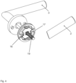
- Fig. 4 shows the kinematic constellation for the rotation blocking of the outside door handle 3 (downwards).
- the interior door handle 2 is raised at an acute angle (to the horizontally stationary exterior door handle 3) with the square spindle 10 and thus also the handle nut 11 remaining stationary.
- the angular difference in the circumferential direction between the small driver lugs 16 and the large driver gaps 17 provides the freewheel required for positive locking.
- the two radial recesses 12 of the handle nut 11 are opposite each other with the two shafts 8 of the projections 7, whose outer circumferences are now enclosed by the small-diameter circular segments of the link ring 13 and block the radial "exit" of the locking elements 9.
- the control of the radial movement of the two diametrically opposed locking elements 9 via the radial bays 12 of the handle nut and the two inner diameters of the link ring 13 is carried out in a form-fitting manner as a so-called positive control without springs, which ensures the absolute functional reliability of the locking mechanism described.
- the force transmission via the pairs of diametrically opposed force transmission points in the locking mechanism prevents any resulting transverse forces from occurring, thus protecting all pivot bearings from wear.
- the freewheel of the interior door handle 2 is used to rotate a (square) shaft 92 of the locking device 90, without the locking elements 9.
- a further embodiment also not shown graphically, comprises the use of said freewheel for the longitudinal drive of a "locking means 15" or a "slide element 16" according to the DE 20 2018 006 769 U1
- the emergency release described in this document according to claim 7 requires an expensive shaft element (12) with a weakened cross-section [corresponding to the square pin 10 of the present description].
- the square pin 10 as a whole can be used to lock and unlock the exterior door handle 3 by being moved in its longitudinal direction by the freewheeling movement of the interior door handle 2 when the latter is lifted.
- the exterior door handle 3 can be axially penetrated by the square pin 10 and can be pushed back from the outside using a nail-like tool.
- the interior door handle 2 is axially and rotationally fixedly connected to the square pin 10 and is - after DE 10 2014 103 994 B4 - during its longitudinal movement of a few millimeters, it is rotationally locked with its door rosette or door plate. This also prevents the exterior door handle 3, which is also rotationally fixed on the square spindle 10, from rotating.
- the interior door handle 2 is (emergency) unlocked, and thus both door handles 2, 3 can be operated.
Landscapes
- Business, Economics & Management (AREA)
- Emergency Management (AREA)
- Lock And Its Accessories (AREA)
Applications Claiming Priority (1)
| Application Number | Priority Date | Filing Date | Title |
|---|---|---|---|
| DE102023133684.3A DE102023133684A1 (de) | 2023-12-01 | 2023-12-01 | Türbeschlag |
Publications (2)
| Publication Number | Publication Date |
|---|---|
| EP4563772A2 true EP4563772A2 (fr) | 2025-06-04 |
| EP4563772A3 EP4563772A3 (fr) | 2025-06-11 |
Family
ID=92966641
Family Applications (1)
| Application Number | Title | Priority Date | Filing Date |
|---|---|---|---|
| EP24203995.6A Pending EP4563772A3 (fr) | 2023-12-01 | 2024-10-01 | Ferrure de porte |
Country Status (2)
| Country | Link |
|---|---|
| EP (1) | EP4563772A3 (fr) |
| DE (1) | DE102023133684A1 (fr) |
Citations (10)
| Publication number | Priority date | Publication date | Assignee | Title |
|---|---|---|---|---|
| DE274245C (fr) | ||||
| DE261857C (fr) | ||||
| DE346576C (de) | 1920-09-01 | 1922-01-05 | Karl Heidelberger | Einsteck- und Kastenschloss |
| DE895575C (de) | 1950-11-30 | 1953-11-05 | Erich Opitz | Feststellvorrichtung fuer Tuergriffe |
| GB2123070B (en) | 1982-07-08 | 1985-09-25 | Micro And Precision Mouldings | Lockable door latch |
| DE102007030655A1 (de) | 2007-07-02 | 2009-01-15 | Hoppe Ag, St. Martin | Betätigungshandhabe für eine Tür |
| EP1683933B1 (fr) | 2005-01-17 | 2012-07-25 | Hoppe Ag | Poignée d'actionnement |
| DE202018006769U1 (de) | 2018-11-22 | 2022-09-12 | Griffwerk GmbH | Türgarnitur mit einer einseitig verriegelbaren Handhabe |
| DE102014103994B4 (de) | 2014-03-24 | 2023-03-09 | Engeltech Gmbh | Griffvorrichtung zur Bedienung eines Schließmechanismus eines Fenster- oder Türflügels |
| DE202023101565U1 (de) | 2022-10-10 | 2023-04-19 | Igor Vanjin | Handhabe mit Axialverriegelung |
Family Cites Families (1)
| Publication number | Priority date | Publication date | Assignee | Title |
|---|---|---|---|---|
| DE102013200156A1 (de) * | 2013-01-08 | 2014-07-10 | Hewi Heinrich Wilke Gmbh | Beschlaganordnung |
-
2023
- 2023-12-01 DE DE102023133684.3A patent/DE102023133684A1/de active Pending
-
2024
- 2024-10-01 EP EP24203995.6A patent/EP4563772A3/fr active Pending
Patent Citations (10)
| Publication number | Priority date | Publication date | Assignee | Title |
|---|---|---|---|---|
| DE274245C (fr) | ||||
| DE261857C (fr) | ||||
| DE346576C (de) | 1920-09-01 | 1922-01-05 | Karl Heidelberger | Einsteck- und Kastenschloss |
| DE895575C (de) | 1950-11-30 | 1953-11-05 | Erich Opitz | Feststellvorrichtung fuer Tuergriffe |
| GB2123070B (en) | 1982-07-08 | 1985-09-25 | Micro And Precision Mouldings | Lockable door latch |
| EP1683933B1 (fr) | 2005-01-17 | 2012-07-25 | Hoppe Ag | Poignée d'actionnement |
| DE102007030655A1 (de) | 2007-07-02 | 2009-01-15 | Hoppe Ag, St. Martin | Betätigungshandhabe für eine Tür |
| DE102014103994B4 (de) | 2014-03-24 | 2023-03-09 | Engeltech Gmbh | Griffvorrichtung zur Bedienung eines Schließmechanismus eines Fenster- oder Türflügels |
| DE202018006769U1 (de) | 2018-11-22 | 2022-09-12 | Griffwerk GmbH | Türgarnitur mit einer einseitig verriegelbaren Handhabe |
| DE202023101565U1 (de) | 2022-10-10 | 2023-04-19 | Igor Vanjin | Handhabe mit Axialverriegelung |
Also Published As
| Publication number | Publication date |
|---|---|
| DE102023133684A1 (de) | 2025-06-05 |
| EP4563772A3 (fr) | 2025-06-11 |
Similar Documents
| Publication | Publication Date | Title |
|---|---|---|
| DE102007044088B4 (de) | Binär codierter Schlüssel und manipulationssicheres Schloss | |
| EP2107187A1 (fr) | Ferrure pour fenêtres ou portes | |
| EP3309333B1 (fr) | Système comprenant un châssis dormant destiné à loger un cadre de vantail | |
| WO2017021410A1 (fr) | Élément d'actionnement pour une serrure à palastre | |
| EP0839247B1 (fr) | Commutateur pour une ferrure de porte ou de fenetre | |
| DE102020005193A1 (de) | Notentriegelung für Falttüren mit hygienischem Schnellmontagesystem für Drückergarnituren | |
| EP3680428A1 (fr) | Dispositif de commande de porte ainsi que porte | |
| EP2796645A2 (fr) | Serrure à pêne dormant d'un meuble | |
| DE102020113825B4 (de) | Betätigungseinrichtung für ein Schloss sowie Schlosssystem mit einer derartigen Betätigungseinrichtung | |
| DE4041218A1 (de) | Wahlweise selbstverriegelndes einriegelschloss | |
| EP2752537A2 (fr) | Agencement de ferrure | |
| EP0763638A1 (fr) | Poignée d'actionnement | |
| DE202013011573U1 (de) | Drückergarnitur für Türen | |
| DE102012012415A1 (de) | Verriegelungsvorrichtung und damit ausgestattete Flügel bzw. Flügelanlage | |
| EP1485555A2 (fr) | Ferrure | |
| EP2060710B1 (fr) | Serrure | |
| DE4244414A1 (fr) | ||
| EP4563772A2 (fr) | Ferrure de porte | |
| EP3165696A1 (fr) | Serrure comprenant un fouillot débrayable | |
| EP2998475B1 (fr) | Levier de jour pour une serrure a battant passif | |
| DE10130268B4 (de) | Schließanlage für Fahrzeugtüren | |
| EP1321605B1 (fr) | Poignée d'actionnement | |
| DE102021118158A1 (de) | Schließeinrichtung für eine Drehvorrichtung | |
| DE19738243C2 (de) | Schloß für Sicherheitstüren | |
| EP0574594B2 (fr) | Ferrure de porte |
Legal Events
| Date | Code | Title | Description |
|---|---|---|---|
| PUAI | Public reference made under article 153(3) epc to a published international application that has entered the european phase |
Free format text: ORIGINAL CODE: 0009012 |
|
| PUAL | Search report despatched |
Free format text: ORIGINAL CODE: 0009013 |
|
| STAA | Information on the status of an ep patent application or granted ep patent |
Free format text: STATUS: THE APPLICATION HAS BEEN PUBLISHED |
|
| AK | Designated contracting states |
Kind code of ref document: A2 Designated state(s): AL AT BE BG CH CY CZ DE DK EE ES FI FR GB GR HR HU IE IS IT LI LT LU LV MC ME MK MT NL NO PL PT RO RS SE SI SK SM TR |
|
| AK | Designated contracting states |
Kind code of ref document: A3 Designated state(s): AL AT BE BG CH CY CZ DE DK EE ES FI FR GB GR HR HU IE IS IT LI LT LU LV MC ME MK MT NL NO PL PT RO RS SE SI SK SM TR |
|
| RIC1 | Information provided on ipc code assigned before grant |
Ipc: E05B 65/10 20060101ALI20250508BHEP Ipc: E05B 13/00 20060101ALI20250508BHEP Ipc: E05B 1/00 20060101AFI20250508BHEP |
|
| STAA | Information on the status of an ep patent application or granted ep patent |
Free format text: STATUS: REQUEST FOR EXAMINATION WAS MADE |
|
| 17P | Request for examination filed |
Effective date: 20251210 |