EP4563776A1 - Ensemble de poignée d'actionnement d'une serrure pour portes de contrôle électronique - Google Patents
Ensemble de poignée d'actionnement d'une serrure pour portes de contrôle électronique Download PDFInfo
- Publication number
- EP4563776A1 EP4563776A1 EP24216275.8A EP24216275A EP4563776A1 EP 4563776 A1 EP4563776 A1 EP 4563776A1 EP 24216275 A EP24216275 A EP 24216275A EP 4563776 A1 EP4563776 A1 EP 4563776A1
- Authority
- EP
- European Patent Office
- Prior art keywords
- handle
- lock
- shaft
- fixed position
- handle assembly
- Prior art date
- Legal status (The legal status is an assumption and is not a legal conclusion. Google has not performed a legal analysis and makes no representation as to the accuracy of the status listed.)
- Pending
Links
Images



Classifications
-
- E—FIXED CONSTRUCTIONS
- E05—LOCKS; KEYS; WINDOW OR DOOR FITTINGS; SAFES
- E05B—LOCKS; ACCESSORIES THEREFOR; HANDCUFFS
- E05B65/00—Locks or fastenings for special use
- E05B65/0025—Locks or fastenings for special use for glass wings
-
- E—FIXED CONSTRUCTIONS
- E05—LOCKS; KEYS; WINDOW OR DOOR FITTINGS; SAFES
- E05B—LOCKS; ACCESSORIES THEREFOR; HANDCUFFS
- E05B47/00—Operating or controlling locks or other fastening devices by electric or magnetic means
- E05B47/0001—Operating or controlling locks or other fastening devices by electric or magnetic means with electric actuators; Constructional features thereof
- E05B47/0012—Operating or controlling locks or other fastening devices by electric or magnetic means with electric actuators; Constructional features thereof with rotary electromotors
-
- E—FIXED CONSTRUCTIONS
- E05—LOCKS; KEYS; WINDOW OR DOOR FITTINGS; SAFES
- E05B—LOCKS; ACCESSORIES THEREFOR; HANDCUFFS
- E05B47/00—Operating or controlling locks or other fastening devices by electric or magnetic means
- E05B47/06—Controlling mechanically-operated bolts by electro-magnetically-operated detents
- E05B47/0676—Controlling mechanically-operated bolts by electro-magnetically-operated detents by disconnecting the handle
- E05B47/068—Controlling mechanically-operated bolts by electro-magnetically-operated detents by disconnecting the handle axially, i.e. with an axially disengaging coupling element
-
- E—FIXED CONSTRUCTIONS
- E05—LOCKS; KEYS; WINDOW OR DOOR FITTINGS; SAFES
- E05B—LOCKS; ACCESSORIES THEREFOR; HANDCUFFS
- E05B47/00—Operating or controlling locks or other fastening devices by electric or magnetic means
- E05B2047/0048—Circuits, feeding, monitoring
- E05B2047/0057—Feeding
- E05B2047/0058—Feeding by batteries
-
- E—FIXED CONSTRUCTIONS
- E05—LOCKS; KEYS; WINDOW OR DOOR FITTINGS; SAFES
- E05B—LOCKS; ACCESSORIES THEREFOR; HANDCUFFS
- E05B47/00—Operating or controlling locks or other fastening devices by electric or magnetic means
- E05B2047/0048—Circuits, feeding, monitoring
- E05B2047/0067—Monitoring
-
- E—FIXED CONSTRUCTIONS
- E05—LOCKS; KEYS; WINDOW OR DOOR FITTINGS; SAFES
- E05B—LOCKS; ACCESSORIES THEREFOR; HANDCUFFS
- E05B47/00—Operating or controlling locks or other fastening devices by electric or magnetic means
- E05B2047/0084—Key or electric means; Emergency release
- E05B2047/0086—Emergency release, e.g. key or electromagnet
-
- E—FIXED CONSTRUCTIONS
- E05—LOCKS; KEYS; WINDOW OR DOOR FITTINGS; SAFES
- E05B—LOCKS; ACCESSORIES THEREFOR; HANDCUFFS
- E05B47/00—Operating or controlling locks or other fastening devices by electric or magnetic means
- E05B2047/0094—Mechanical aspects of remotely controlled locks
- E05B2047/0095—Mechanical aspects of locks controlled by telephone signals, e.g. by mobile phones
-
- E—FIXED CONSTRUCTIONS
- E05—LOCKS; KEYS; WINDOW OR DOOR FITTINGS; SAFES
- E05B—LOCKS; ACCESSORIES THEREFOR; HANDCUFFS
- E05B63/00—Locks or fastenings with special structural characteristics
- E05B63/0065—Operating modes; Transformable to different operating modes
Definitions
- the present invention generally relates to systems for operating electronically controlled locks.
- the invention relates to a handle assembly for operating a lock for doors, particularly, but not restrictively, glass doors, including an electronic operation control.
- Such lock systems comprise handle assemblies for operating the locks and electronic systems for controlling the access to a door.
- An electromechanical lock system for doors of the known type comprises a handle assembly and a housing for the lock, for example.
- the lock housing can be provided with an actuator, such as an electric motor, for bringing a lock latch, which slides inside such a housing, from a closing or locked position of the lock to an unlocking position.
- an actuator can be controlled, for example, in a wireless manner by means of an electronic control module associated with the lock.
- the lock of a door can thus be unlocked without requiring a physical key.
- an electronic signal transmitter can be used, such as a smartphone, for example, which can send an unlock signal to the electronic control module. Therefore, for example, the operation of such a signal transmitter can be remotely managed automatically by means of communication with a server, for example.
- the handle assembly and the lock housing of the electromechanical lock system of the known type are generally shaped as monobloc structures having significant weights and volumes which make them inadequate for glass door applications.
- a handle assembly for operating a lock for doors comprising:
- the handle assembly further comprises:
- a handle assembly for a lock having a modular structure comprising an electromechanical handle and a mechanical handle.
- the electromechanical handle is configured, in a first example, to be fastened on a first surface of the door by means of a box-shaped housing of electromechanical components, of the handle assembly connected to such an electromechanical handle.
- the mechanical handle is configured to be fastened to a second surface of the door, opposing the first surface, through a box-shaped housing of mechanical components of the handle assembly, which includes a latch.
- the electromechanical handle is configured to be fastened on the first surface of the door through the box-shaped housing of mechanical components which includes the latch.
- the mechanical handle is fastened on the second surface of the door by means of a respective box-shaped housing of electromechanical components of the handle assembly, connected to such a mechanical handle.
- the present invention further relates to an electronic control system for controlling the handle assembly of the invention, according to claim 12.
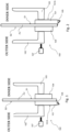
- a handle assembly for operating a lock 101A, 201A for doors PV, PL, according to the present invention is indicated by reference numerals 100, 100', 200 in three embodiments.
- handle assembly 100, 100' of the invention is particularly advantageous for application to a glass door PV, as in the examples in Figures 1-2 , in an embodiment such a handle assembly 200 is also applicable to a wood door PL.
- the handle assembly 100 comprises a first handle 103, in particular an electromechanical handle according to the present invention, operatively associated with a first surface S1 of the glass door PV.
- the first handle 103 is connected to a first lock housing 104 fastened to the first surface S1 of the glass door PV.
- a first lock housing 104 is configured to house electromechanical components of the handle assembly 100, as clarified below.
- the handle assembly 100 further comprises a second handle 102, in particular a mechanical handle, operatively associated with a second surface S2 of the glass door PV opposing the first surface S1.
- a second handle 102 is connected to a second lock housing 101 fastened to the aforesaid second surface S2 of the glass door PV.
- Such a second lock housing 101 comprises, in particular, a latch 105 that can slide inside the housing and further mechanical components of the lock of the known type. For such a reason, such a second lock housing 101 is not described in detail below.
- the aforesaid second handle 102 includes a respective lock cylinder 106 (shown in Figure 6 ) operable by means of a key 107.
- the handle assembly 100' comprises the aforesaid first handle 103, in particular, an electromechanical handle according to the present invention, operatively associated with the first surface S1 of the glass door PV.
- the handle assembly 100' further comprises a second handle 102, in particular a mechanical handle, operatively associated with the second surface S2 of the glass door PV opposing the first surface S1.
- a second handle 102 is connected to a respective first lock housing 104' fastened to the second surface S2 of the glass door PV.
- a first lock housing 104' similarly to the aforesaid housing 104, is configured to house electromechanical components of the handle assembly 100', as clarified below.
- the second handle 102 includes a respective lock cylinder 106 (shown in Figure 6 ) operable by means of a key 107.
- the handle assembly 200 comprises the first handle 103, in particular an electromechanical handle according to the present invention, operatively associated with a first surface S1 of the wood door PL.
- the first handle 103 is connected to the first lock housing 104 fastened to the first surface S1 of the wood door PL and configured to house electromechanical components of the handle assembly 200.
- the handle assembly 200 further comprises the second handle 102, in particular a mechanical handle, operatively associated with a second surface S2 of the wood door PL opposing the first surface S1.
- the second handle 102 is connected to a further second lock housing 201 having a first housing portion fastened to the aforesaid second surface S2 of the wood door PL and a second portion housed inside door PL itself.
- Such a second lock housing 201 comprises a respective latch 205 that can slide inside the second housing portion.
- the aforesaid second handle 102 includes a respective lock cylinder 106 (shown in Figure 6 ) operable by means of a key 107.
- the second surface S2 of the glass door PV or wood door PL is the surface facing outwards (outer side) of an environment, e.g., a hotel room or an office, which can be accessed through door PV or PL.
- the first surface S1 of the glass door PV or wood door PL faces the interior (inner side) of such an environment, room or office.
- the first handle 103 of the invention is the handle configured to be operated manually by a user to leave the aforesaid room or office.
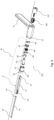
- the first handle 103 of the electromechanical type according to the present invention is described in greater detail with reference to the example in Figure 4 .
- Such a first handle 103 comprises a handle body 1, made of aluminum, for example, comprising a first body portion 1a, or grip portion, protruding orthogonally from a second body portion 1b, for the connection of the first handle 103 with the aforesaid first 104 or second 101 lock housings.
- the second body portion 1b of handle 103 is shaped to delimit a respective, substantially cylindrical-shaped housing compartment 1'.
- the first handle 103 comprises, inside the aforesaid cylindrical housing compartment 1', an insulating washer 2 and a gear motor 3 connected to a first gear motor half-shell 4.
- Such a first half-shell 4 is provided with a gear motor shaft or joint 5 reversibly rotatable from a first fixed position, corresponding to the unlocked or open lock configuration, to a second fixed position, corresponding to the locked or closed lock configuration.
- the rotation of joint 5 from the first fixed position to the second fixed position corresponds to a rotation of joint 5 of about 90° in counterclockwise direction.
- the inverse rotation, from the second fixed position to the first fixed position, corresponds to a rotation of joint 5 of about 90° in clockwise direction.
- the first handle 103 comprises detection means 71, 72, 95, 96 of the aforesaid first and second fixed positions reached by joint 5 following the aforesaid rotations.
- detection means are embodied by a first 71 and second 72 magnetic field sensor housed in a first electronic circuit 7 of the first handle 103.
- Such magnetic field sensors 71, 72 are actuatable by a first 95 and second 96 permanent magnet, respectively, fastened on an outer surface of joint 5 so as to be at an angular distance of 90° from each other.
- the first handle 103 further comprises a second gear motor half-shell 6 adapted to be fitted onto said first half-shell 4 and a bushing 10, having a first end adapted to engage the second half-shell 6 and an opposing second end adapted to engage a shaft 13, in particular, a square shaft of the lock, shown in Figures 6 , 7 or 8 , for example.
- first handle 103 is connected in a non-rotatable manner to the aforesaid shaft 13 and is couplable to the first 104, and to the second 101 lock housing to control, by means of such a shaft 13, latch 105, 205 following the manual rotation of the handle by a user, allowing the operation of the lock both in the open lock configuration and in the closed lock configuration.
- first handle 103 comprises first electronic control means 7, in particular, a first electronic circuit 7 of the printed type (Printed Circuit Board or PCB) mentioned above, adapted to control the operation of the gear motor 3 and detect the rotation of joint 5 from the first fixed position to the second fixed position, and vice versa.
- first electronic control means 7 in particular, a first electronic circuit 7 of the printed type (Printed Circuit Board or PCB) mentioned above, adapted to control the operation of the gear motor 3 and detect the rotation of joint 5 from the first fixed position to the second fixed position, and vice versa.
- the first handle 103 further comprises a fairlead element 8 configured to facilitate the wiring of power cables of the first electronic circuit 7 and an annular bushing 9 adapted to engage a coupling edge 1" of the second body portion 1b of handle body 103 for connecting such a second portion 1b with the first 104 or second 101 lock housing.
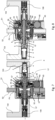
- the handle assembly 100, 100', 200 comprises the aforesaid shaft 13 extending along a shaft axis X, orthogonally to the first S1 and second S2 surface of door PV, PL.
- a shaft 13 has a first end 13' connected to bushing 10 of the first handle 103 to be integral with the first handle and to rotate always integrally with such a handle.
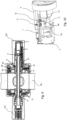
- shaft 13 has a second end 13" adapted to engage a mechanism M of the second handle 102, which is described below with reference to Figure 6 .
- the handle assembly 100, 100', 200 comprises a rod 14 fitted inside shaft 13 along axis X to be coaxial with such a shaft.
- a rod 14 has a respective first end 14' fastened to joint 5 of the first handle 103 to rotate reversibly with such a joint 5 from the first fixed position, corresponding to the open lock configuration, to the second fixed position, corresponding to the closed lock configuration, and vice versa.
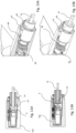
- Figure 11A shows rod 14 connected to joint 5 in the aforesaid first fixed position, or “vertical rod”, corresponding to the open lock configuration.
- Figure 11B shows rod 14 connected to joint 5 in the second fixed position, or “horizontal rod”, corresponding to the closed lock configuration.
- a second end 14" of rod 14, in particular, T-shaped, is adapted to engage mechanical components 42, 43, 45 and 48 of mechanism M of the second handle 102 to enable a direct connection of the second handle 102 with shaft 13, and therefore with the first handle 103.
- the second handle 102 is rotatable integrally with the first handle 103 to operate latch 105, 205 of the lock.
- the second handle 102 comprises the aforesaid mechanism M consisting of a plurality of mechanical components.
- the second handle 102 comprises a handle rotation shaft 42 connected to the second end of the square shaft 13.
- a handle rotation shaft 42 includes an anti-friction bushing 47 provided with a Seeger ring 46.
- the aforesaid anti-friction bushing 47 is configured to be fitted onto the handle rotation shaft 42 by surrounding it.
- the handle rotation shaft 42 and the anti-friction bushing 47 are configured to engage a coupling edge 41' of a respective cylindrical housing compartment, of the through type, of body 41 of the second handle 102.
- the second handle 102 further comprises a respective lifter shaft 43 configured to engage the second end 14" of rod 14 when the latter is inserted into shaft 13.
- a lifter shaft 43 is fitted inside the handle rotation shaft 42 together with a cylindrical cam 45 and a translating cam 48.
- the second handle 102 comprises a respective joint 44 associated with an actuator pin element 50, which are located inside the cylindrical housing of the handle body 41.
- a spring 49 a helical spring in particular, is interposed between such a joint 44 and the translating cam 48.
- the second handle 102 further comprises the lock cylinder 106 operable by means of key 107 and housed in the cylindrical compartment of the handle body 41 in a position opposing the coupling edge 41'.
- a rotation of the lock cylinder 106 by means of key 107 is configured to act on the aforesaid mechanical components of the second handle 102 to mechanically rotate rod 14 from the second fixed position, in which the lock is in closed configuration, to the first position, i.e., in open configuration.
- Such an operation by means of key 107 is also usable to bring rod 14 back to the second fixed position, i.e., to close the lock again.
- first lock housing 104 is configured to be connected to the first handle 103, i.e., to the electromechanical handle, of the handle assembly 100, 200 in Figures 1 and 3 .
- Such a first lock housing 104 which is box-shaped, comprises a base wall 51, for example made of aluminum, fastenable to the first surface S1 of door PV, PL by means of fastening screws 52.
- a base wall 51 is adapted to be coupled to a cover element 63 of the first housing 104, for example made of aluminum, comprising a bottom wall 63a, opposing the base wall 51, and connected in one piece to two first side walls 63b protruding orthogonally from the bottom wall 63a towards the base wall 51 and joined to each other by a second side wall 63c.
- the cover element 63 is configured to delimit, with the bottom wall 51, a respective compartment of the first lock housing 104 which includes the components described below.
- the first lock housing 104 comprises a diaphragm element 55 adapted to be coupled, for example in a snap-fit manner, to the base wall 51, and an elastic element 53, e.g., a torsional spring, interposed between the base wall 51 and the diaphragm element 55.
- an elastic element 53 e.g., a torsional spring
- the first lock housing 104 further comprises second electronic control means 58, in particular, a second electronic circuit 58 of the printed type (PCB) fastenable to the diaphragm element 55 by means of further screws 54.
- second electronic control means 58 in particular, a second electronic circuit 58 of the printed type (PCB) fastenable to the diaphragm element 55 by means of further screws 54.
- PCB printed type
- the first housing 104 further comprises a respective tubular bushing 57, interposed between the second printed electronic circuit 58 and the diaphragm element 55.
- a tubular bushing 57 is provided with two opposing protrusions 57a in radial direction. At least one of such protrusions 57a is configured to house a third permanent magnet 57' adapted to cooperate with a third magnetic field sensor 58' associated with the second printed electronic circuit 58 (shown in Figure 12 ).
- the aforesaid tubular bushing 57 is rotatable integrally with the first handle 103 and allows detecting, following the angular displacement of the third permanent magnet 57' with respect to sensor 58', the operation of the first handle 103 by a user.
- the first lock housing 104 further comprises a fairlead cap 61.
- the first lock housing 104 further comprises power supply means 59, 60 of the handle assembly 100, 200, in particular, of the second electronic circuit 58 housed in the first lock housing 104, and of the first electronic circuit 7 housed in the first handle 103.
- power supply means are embodied in a battery 60, e.g., a CR123A battery, insertable into a flexible tab 59 for inserting/removing battery 60.
- a flexible tab 59 is shaped to be coupled to the diaphragm element 55.
- protruding portions 55' of diaphragm 55 are configured to engage slots 59' obtained in tab 59 (two slots).
- the flexible tab 59 is configured to isolate an electrical contact element 56, provided in the diaphragm element 55, from the metal cover 63 of the first lock housing 104.
- the first lock housing 104 further comprises a magnetic fastening cover 65 configured to be connected to the cover element 63 of housing 104 to oppose the second side wall 63c.
- the magnetic cover 65 is adapted to close again the housing compartment of battery 60 in the first housing 104, separating such a battery from the external environment.
- the magnetic cover 65 is separable from the first lock housing 104 by employing a dedicated tool which allows overcoming the magnetic attraction linking cover 65 with the first housing 104.
- first lock housing 104' is configured to be connected to the second handle 102, i.e., to the mechanical handle, of the handle assembly 100' in Figure 2 .
- housing 104' which are equal or similar to those described for the example of housing 104 are indicated by means of the same reference numerals.
- Such a first box-shaped lock housing 104' comprises a base wall 51, for example made of aluminum, fastenable to the second surface S2 of door PV, PL by means of fastening screws 52.
- a base wall 51 is adapted to be coupled to a cover element 63 of the first housing 104', for example made of aluminum, comprising a bottom wall 63a, opposing the base wall 51, and connected in one piece to two first side walls 63b protruding orthogonally from the bottom wall 63a towards the base wall 51 and joined to each other by a second side wall 63c.
- the cover element 63 is configured to delimit, with the bottom wall 51, a respective compartment of the first lock housing 104' which includes the components described below.
- the first lock housing 104' comprises a diaphragm element 55 adapted to be coupled, for example in a snap-fit manner, to the base wall 51, and an elastic element 53, e.g., a torsional spring, interposed between the base wall 51 and the diaphragm element 55.
- an elastic element 53 e.g., a torsional spring
- the first lock housing 104' further comprises second electronic control means 58, in particular, a second electronic circuit of the printed type (PCB) fastenable to the diaphragm element 55 by means of further screws 54.
- PCB printed type
- the first housing 104' further comprises a respective tubular bushing 57 interposed between the second printed electronic circuit 58 and the diaphragm element 55.
- a tubular bushing 57 is provided with a radial protrusion 57a configured to house a third permanent magnet 57' adapted to cooperate with a third magnetic field sensor 58' associated with the second printed electronic circuit 58 (shown in Figure 12 ).
- the aforesaid tubular bushing 57 is rotatable integrally with the first handle 103 and allows detecting, following the angular displacement of the third permanent magnet 57' with respect to sensor 58', the operation of the first handle 103 by a user.
- the first lock housing 104' further comprises power supply means 59, 60 of the handle assembly 100', in particular, of the second electronic circuit 58 housed in the first lock housing 104' and of the first electronic circuit 7 housed in the first handle 103.
- power supply means are embodied in a battery 60, e.g., a CR123A battery, insertable into a flexible tab 59 for inserting/removing battery 60.
- a flexible tab 59 is shaped to be coupled to the diaphragm element 55.
- protruding portions 55' of such a diaphragm 55 are configured to engage slots 59' obtained in tab 59 (two slots).
- the flexible tab 59 is configured to isolate an electrical contact element 56, provided in the diaphragm element 55, from the metal cover 63 of the first housing 104'.
- the first housing 104' further comprises a magnetic fastening cover 65 configured to be connected to the cover element 63 of housing 104' to oppose the second side wall 63c.
- the magnetic cover 65 is adapted to close again the housing compartment of battery 60, separating such a battery from the external environment. Note, in particular, that the magnetic cover 65 is separable from the first lock housing 104' by employing a dedicated tool which allows overcoming the magnetic attraction linking cover 65 with the first housing.
- first housing 104' comprises an annular anti-rotation bushing 64 for a mechanical handle for advantageously promoting the connection of the second handle 102 to the first lock housing 104'.
- first housing 104' comprises an annular-shaped torsional spring for a mechanical handle 66 and a spring cam 67, being also annular, which are interposed between the second electronic circuit 58 and the bottom wall 63a of the cover element 63.
- the base wall 51, the diaphragm element 55, the elastic element 53, the second electronic circuit 58 and the cover element 63 of the first lock housing 104 or 104' each comprise a respective through hole F coaxial to axis X. As shown in Figures 7, 8 , and 9 , such mutually coaxial through holes are adapted to promote the insertion of the square shaft 13 into the lock housing 104, 104' to connect the first handle 103 to the second handle 102.
- An electronic control system of the handle assembly 100, 100', 200 of the invention is indicated by reference numeral 600 and is described in relation to Figure 12 .
- Such an electronic system 600 comprises the handle assembly 100, 100', 200 according to the present invention.
- such a system 600 comprises the gear motor 3 drivable to move, through the rotation of joint 5, rod 14 of the handle assembly 100, 100', 200 from the first fixed position to the second fixed position, and vice versa.
- Such an electronic control system 600 comprises the first electronic circuit 7 housed in the first handle 103 and the second electronic circuit 58 housed in the first lock housing 104, 104'.
- the electronic control system 600 further comprises the aforesaid battery 60 adapted to provide the second electronic circuit 58 with a supply voltage AL, e.g., 3 Volts, for supplying the electronic circuits of such a second circuit 58 and those of the first electronic circuit 7.
- a supply voltage AL e.g. 3 Volts
- the first electronic circuit 7 is adapted to transfer the aforesaid power supply voltage AL to the gear motor 3 to drive it.
- the first electronic circuit 7 is adapted to receive, through the magnetic field sensors 71, 72, a position status signal IPMot of the gear motor 3.
- a position status signal IPMot is representative of the position rod 14 takes in the open or closed lock configuration.
- the first control circuit 7 is adapted to know, at every instant, the status of the lock, whether it is operated electronically through the first 7 and the second 58 electronic circuit, or it is maneuvered through key 107.
- the second electronic control circuit 58 of the electronic control system 600 is configured to house a main electronic control unit 90 (CPU) of the handle assembly 100, 100', 200, e.g., a microprocessor or microcontroller. Moreover, the second electronic control circuit 58 comprises a wireless communication module 91 to allow such a microprocessor 90 to communicate with a user-portable electronic device 80 of system 600, e.g., a smartphone. Such a communication with the smartphone occurs, for example, according to the Bluetooth standard.
- the second electronic control circuit 58 further comprises the third magnetic field sensor 58', similar to the sensors 71, 72 associated with the first electronic control circuit 7 of the first handle 103, which allows reading the position of handle 103, whether resting or operated, on the basis of a handle status input signal ISM.
- the electronic control unit 90 of the second circuit 58 is configured to receive, in input from smartphone 80, a lock opening/closing control signal IA and to send an output signal OSM on the status of the first handle 103 to smartphone 80, on the basis of the information received from the first magnetic field sensor 58'.
- first 7 and second 58 electronic control circuits of the electronic system 600 are connected to each other by suitable wiring for exchanging other information INF.
- the handle assembly 100, 100', 200 of the invention can take two independent operating modes, selectable by a user through a software application executed on the smartphone 80 of the control system 600.
- key 107 serves only as an emergency device in the case of any type of malfunction of the electronic components associated with the first 7 and/or second 58 electronic circuits or if the battery 60 is exhausted.
- the status of the handle assembly 100, 100', 200 and of the lock is constantly monitored by the three aforesaid magnetic field sensors 71, 72, 58': one (sensor 58') monitors if the first handle 103, i.e., the electromechanical handle, was operated by a user, i.e., was rotated from the resting position; the other two (sensors 71, 72) read alternatively if rod 14 is in the first or second fixed position.
- first handle 103 is always the handle mounted on surface S1 of door PV, PL facing the interior of a room, a user will always be able to leave such a room, irrespective of the malfunctioning that can occur in the handle assembly. Indeed, the first handle 103 is always mechanically in direct contact with latch 105, 205 which allows opening door PL, PV.
- a first operating mode (“office” mode) includes employing the handle assembly 100, 100', 200 and the related lock in a door PV, PL for accessing an office.
- office mode it is desired for lock 101, 201 to always be in open or unlocked configuration, unless it is the user to close it again voluntarily through the software application in execution on the smartphone 80.
- the user can both unlock the lock through smartphone 80 and the related application, and then by operating the first handle 103, and leave directly by operating the first handle 103.
- the third magnetic field sensor 58' detects the change in status with the handle status signal ISM and the second electronic control circuit 58 is adapted to bring the lock to the unlocked configuration.
- the user can thus enter the office again, even immediately, from the outside.
- the lock remains open indefinitely until it is locked again through the application software and smartphone 80. In this case, the user never runs the risk of remaining locked out of the office because the lock will not close automatically.
- a second operating mode (“hospitality” mode) provides employing the handle assembly 100, 100', 200 and the related lock in a hotel or residential hotel room. In such an operating mode, it is desired for the lock to be always closed or locked.
- the user can enter the room only by selecting the open configuration (unlocked lock) for the lock by means of the software application and the smartphone 80 or with the emergency key 107.
- the user can always leave the room by operating the first handle 103 from the inside of the hotel room because such a handle is always capable of operating the latch 105, 205.
- system 600 reads the movement of the first handle 103 (through sensor 58') and locks lock 101, 201 again without waiting for such a preset time interval to lapse.
- the handles 103, 102 can be operated only once to open door PV, PL when the lock is unlocked. Once operated, the lock is locked again and it will be necessary to unlock it by means of the application and smartphone 80. This means, in particular, that the user can always close door PV, PL behind him/her with the certainty that the door will not be openable by anyone who does not have the required access rights.
- the user can access the room again only if someone else opens door PV, PL through the application, or with the emergency key 107.
- the handle assembly 100, 100', 200 for operating a lock for doors of the present invention has various advantages and achieves the preset objects.
- the handle assembly of the invention is advantageously applicable to glass door applications.
Landscapes
- Lock And Its Accessories (AREA)
Applications Claiming Priority (1)
| Application Number | Priority Date | Filing Date | Title |
|---|---|---|---|
| IT102023000025644A IT202300025644A1 (it) | 2023-12-01 | 2023-12-01 | Gruppo di maniglia per l’azionamento di una serratura per porte con controllo elettronico dell’azionamento |
Publications (1)
| Publication Number | Publication Date |
|---|---|
| EP4563776A1 true EP4563776A1 (fr) | 2025-06-04 |
Family
ID=90458449
Family Applications (1)
| Application Number | Title | Priority Date | Filing Date |
|---|---|---|---|
| EP24216275.8A Pending EP4563776A1 (fr) | 2023-12-01 | 2024-11-28 | Ensemble de poignée d'actionnement d'une serrure pour portes de contrôle électronique |
Country Status (2)
| Country | Link |
|---|---|
| EP (1) | EP4563776A1 (fr) |
| IT (1) | IT202300025644A1 (fr) |
Citations (3)
| Publication number | Priority date | Publication date | Assignee | Title |
|---|---|---|---|---|
| EP0978611A2 (fr) * | 1998-07-31 | 2000-02-09 | HEWI Heinrich Wilke GmbH | Système de serrure |
| US20140165673A1 (en) * | 2012-12-18 | 2014-06-19 | Stanley Security Solutions, Inc. | Lock assembly having lock position sensor |
| WO2021092660A1 (fr) * | 2019-11-14 | 2021-05-20 | Assa Abloy Australia Pty Limited | Système de serrure complète électronique ayant des capacités de communication |
-
2023
- 2023-12-01 IT IT102023000025644A patent/IT202300025644A1/it unknown
-
2024
- 2024-11-28 EP EP24216275.8A patent/EP4563776A1/fr active Pending
Patent Citations (3)
| Publication number | Priority date | Publication date | Assignee | Title |
|---|---|---|---|---|
| EP0978611A2 (fr) * | 1998-07-31 | 2000-02-09 | HEWI Heinrich Wilke GmbH | Système de serrure |
| US20140165673A1 (en) * | 2012-12-18 | 2014-06-19 | Stanley Security Solutions, Inc. | Lock assembly having lock position sensor |
| WO2021092660A1 (fr) * | 2019-11-14 | 2021-05-20 | Assa Abloy Australia Pty Limited | Système de serrure complète électronique ayant des capacités de communication |
Also Published As
| Publication number | Publication date |
|---|---|
| IT202300025644A1 (it) | 2025-06-01 |
Similar Documents
| Publication | Publication Date | Title |
|---|---|---|
| EP4261369B1 (fr) | Serrure cylindrique à commande électronique | |
| US20130067969A1 (en) | Electronic Cabinet/Drawer Lock System | |
| US8770633B2 (en) | Latch actuator and latch using same | |
| CA3019169A1 (fr) | Dispositif de securite pour contenir et partager une cle | |
| LU100905B1 (en) | Changing a State of a Lock | |
| WO2012119184A1 (fr) | Ensemble serrure | |
| EP4206428A1 (fr) | Liaison de frappe et récepteur dans un mur | |
| EP4334552B1 (fr) | Dispositif d'actionnement pour dispositif de verrouillage, et dispositif de verrouillage | |
| CN108915413B (zh) | 一种箱柜门锁及锁控系统 | |
| GB2624498A (en) | Locking device | |
| CN112360240A (zh) | 智能锁具 | |
| GB2582608A (en) | A window or door leaf system | |
| WO2017142471A1 (fr) | Dispositif d'actionnement de serrure de porte électronique | |
| EP4261367A1 (fr) | Serrure à mortaiser électronique | |
| IT202300025644A1 (it) | Gruppo di maniglia per l’azionamento di una serratura per porte con controllo elettronico dell’azionamento | |
| CN112360241A (zh) | 锁具系统和开闭锁方法 | |
| KR102218094B1 (ko) | 전자식 도어 잠금 장치 | |
| EP1588003A1 (fr) | Verrou electromagnetique actionne mecaniquement | |
| KR20160119421A (ko) | 슬라이딩 개폐 구조의 전자식 잠금 기기 | |
| CN110939317A (zh) | 配有进入监控系统的控制把手 | |
| KR20020047648A (ko) | 잠금장치 | |
| KR20020033671A (ko) | 도어핸들용 원격제어 전자식 키박스 | |
| EP1951975A2 (fr) | Systeme de verrouillage optimise | |
| JP2007198062A (ja) | 着脱可能な電子錠装置 | |
| WO2020086045A2 (fr) | Dispositif permettant d'actionner automatiquement des verrous de porte existants |
Legal Events
| Date | Code | Title | Description |
|---|---|---|---|
| PUAI | Public reference made under article 153(3) epc to a published international application that has entered the european phase |
Free format text: ORIGINAL CODE: 0009012 |
|
| STAA | Information on the status of an ep patent application or granted ep patent |
Free format text: STATUS: THE APPLICATION HAS BEEN PUBLISHED |
|
| AK | Designated contracting states |
Kind code of ref document: A1 Designated state(s): AL AT BE BG CH CY CZ DE DK EE ES FI FR GB GR HR HU IE IS IT LI LT LU LV MC ME MK MT NL NO PL PT RO RS SE SI SK SM TR |
|
| STAA | Information on the status of an ep patent application or granted ep patent |
Free format text: STATUS: REQUEST FOR EXAMINATION WAS MADE |
|
| 17P | Request for examination filed |
Effective date: 20251124 |
|
| GRAP | Despatch of communication of intention to grant a patent |
Free format text: ORIGINAL CODE: EPIDOSNIGR1 |
|
| RIC1 | Information provided on ipc code assigned before grant |
Ipc: E05B 47/00 20060101AFI20251224BHEP Ipc: E05B 47/06 20060101ALI20251224BHEP Ipc: E05B 65/00 20060101ALI20251224BHEP Ipc: E05B 63/00 20060101ALN20251224BHEP |
|
| STAA | Information on the status of an ep patent application or granted ep patent |
Free format text: STATUS: GRANT OF PATENT IS INTENDED |
|
| INTG | Intention to grant announced |
Effective date: 20260128 |
|
| GRAS | Grant fee paid |
Free format text: ORIGINAL CODE: EPIDOSNIGR3 |
|
| GRAA | (expected) grant |
Free format text: ORIGINAL CODE: 0009210 |
|
| STAA | Information on the status of an ep patent application or granted ep patent |
Free format text: STATUS: THE PATENT HAS BEEN GRANTED |