EP4563809A1 - Structures de profil aérodynamique à bruit réduit - Google Patents
Structures de profil aérodynamique à bruit réduit Download PDFInfo
- Publication number
- EP4563809A1 EP4563809A1 EP24214765.0A EP24214765A EP4563809A1 EP 4563809 A1 EP4563809 A1 EP 4563809A1 EP 24214765 A EP24214765 A EP 24214765A EP 4563809 A1 EP4563809 A1 EP 4563809A1
- Authority
- EP
- European Patent Office
- Prior art keywords
- profile structure
- standing waves
- sound
- structure according
- aerodynamic profile
- Prior art date
- Legal status (The legal status is an assumption and is not a legal conclusion. Google has not performed a legal analysis and makes no representation as to the accuracy of the status listed.)
- Pending
Links
Images





Classifications
-
- F—MECHANICAL ENGINEERING; LIGHTING; HEATING; WEAPONS; BLASTING
- F03—MACHINES OR ENGINES FOR LIQUIDS; WIND, SPRING, OR WEIGHT MOTORS; PRODUCING MECHANICAL POWER OR A REACTIVE PROPULSIVE THRUST, NOT OTHERWISE PROVIDED FOR
- F03D—WIND MOTORS
- F03D1/00—Wind motors with rotation axis substantially parallel to the air flow entering the rotor
- F03D1/06—Rotors
- F03D1/065—Rotors characterised by their construction elements
- F03D1/0675—Rotors characterised by their construction elements of the blades
-
- B—PERFORMING OPERATIONS; TRANSPORTING
- B64—AIRCRAFT; AVIATION; COSMONAUTICS
- B64C—AEROPLANES; HELICOPTERS
- B64C3/00—Wings
-
- F—MECHANICAL ENGINEERING; LIGHTING; HEATING; WEAPONS; BLASTING
- F03—MACHINES OR ENGINES FOR LIQUIDS; WIND, SPRING, OR WEIGHT MOTORS; PRODUCING MECHANICAL POWER OR A REACTIVE PROPULSIVE THRUST, NOT OTHERWISE PROVIDED FOR
- F03D—WIND MOTORS
- F03D1/00—Wind motors with rotation axis substantially parallel to the air flow entering the rotor
- F03D1/06—Rotors
- F03D1/065—Rotors characterised by their construction elements
- F03D1/0675—Rotors characterised by their construction elements of the blades
- F03D1/0679—Load carrying structures, e.g. beams
- F03D1/0684—Shear webs
-
- F—MECHANICAL ENGINEERING; LIGHTING; HEATING; WEAPONS; BLASTING
- F03—MACHINES OR ENGINES FOR LIQUIDS; WIND, SPRING, OR WEIGHT MOTORS; PRODUCING MECHANICAL POWER OR A REACTIVE PROPULSIVE THRUST, NOT OTHERWISE PROVIDED FOR
- F03D—WIND MOTORS
- F03D80/00—Details, components or accessories not provided for in groups F03D1/00 - F03D17/00
- F03D80/005—Details, components or accessories not provided for in groups F03D1/00 - F03D17/00 for reducing noise pollution
Definitions
- the invention relates to aerodynamic profile structures, such as rotor blades for wind turbines or wings of aircraft, in which standing waves (room modes) occurring in the interior of the rotor blade are damped, prevented or detuned by suitable measures.
- the invention relates in particular to such profile structures of the aforementioned shapes which can avoid and minimize standing waves in the frequency range below the Schröder frequency, which depends on the room size and geometry, by structurally modifying measures inside the profile structure.
- the invention also relates to corresponding profile structures which can influence unwanted sound events of any kind, even above the Schröder frequency, by means of additional passive and active damping devices mounted in the interior.
- the interior of rotor blades or other aerodynamic profiles is a highly reverberating cavity with long reverberation times (5s and more).
- the sound is amplified primarily by strong standing waves.
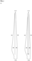
- the usual blade design of such rotor blades in the state of the art (see Fig. 1 ) consists of two or three cavities that extend along the longitudinal axis of the rotor blade. Standing waves can form primarily in these elongated cavities in the transverse and longitudinal directions. With a maximum diameter of 3m (5MW class) at the blade root of a wind turbine rotor blade, the deepest standing waves in the transverse direction are at approximately 60Hz. As the blade tapers along its length, the wavelengths become shorter and the frequencies of the standing waves in the transverse direction become higher.
- 5MW class 3m
- standing waves occur continuously from approximately 60Hz, and these frequencies are more or less pronounced depending on the shape of the blade.
- the detected frequencies of the standing waves in the transverse direction are between 70Hz and 125Hz.
- the dimensions of current rotor blades are much larger (70m and more).
- standing waves in the longitudinal direction occur at 2.5Hz and multiples thereof.
- Low-frequency standing waves (2.5 Hz-200 Hz) in the longitudinal direction of the rotor blade are particularly energetic.
- the standing waves in current rotor blades have long reverberation times (low damping) because the round and reverberant inner surfaces of the blade reflect the sound waves well and thus a lot of sound energy is stored in the blade, i.e. little energy is dissipated per unit of time. Reverberation times of 5 s and more have been measured.
- the standing waves in the central cavity (7) in blades with three cavities in particular contain a lot of energy because the contour of this usually rectangular cavity only changes in height over the length of the rotor blade. This means that the standing The wave is only slightly disturbed and can store a lot of energy when excited at a constant frequency. This increases the amplitude of the sound pressure fluctuations, and thus also the impact on the blade structure and the sound radiation into the environment. This is especially true when the excitation frequencies coincide with the frequency of the standing wave at the turbine's rated speed.
- Gearboxes and generators in wind turbines introduce sinusoidal forces into the WT structure during operation.
- the resulting vibrations in the audible frequency range of 20–20,000 Hz can, in unfavorable cases, be radiated into the surrounding area via the WT's external surfaces, i.e., primarily the blades, tower, and nacelle, and thus cause disturbances to humans and the environment.
- Measurement methods are specified in the DIN EN 61400-11 standard.
- the area over which sound is radiated depends on the frequency, the transfer path from the sound source (usually the gearbox and/or generator) to the radiating surface, and the radiation efficiency of the respective surface.
- the intensity of the noise perceived from outside depends on the size, position, direction and frequency of the forces introduced into the generator and gearbox, the natural vibration behavior of the wind turbine structure, the size of the radiating surface and the degree of radiation of the structural vibration into the air.
- broadband noises mostly originate from aerodynamic excitations caused by separation and flow noise at the blade tip, trailing edge, and leading edge. Although these noises are usually generated outside the blade, they can penetrate the blade structure into the rotor blade and are amplified by the standing waves in the blade. They are radiated over a large area at particularly critical points on the blade surface. The position of the radiation depends on the characteristics of the standing wave and the structural behavior of the blade. This is particularly critical when sound pressure maxima of the standing wave impinge on particularly large, easily excited, or soft parts of the blade structure. These blade surfaces then act as loudspeakers, radiates the sound into the environment. Since the surfaces of the blade are usually very large, relatively thin-walled, and soft, it is assumed that the loudspeaker is relatively large.
- a standing wave In a standing wave, the air molecules on either side of a node oscillate symmetrically. Oscillation nodes are therefore locations of greatest pressure change and thus represent pressure antinodes. The pressure is constant in the oscillation antinodes, so that these are pressure nodes. The sound pressure (alternating pressure) in the standing wave is therefore zero in the pressure nodes and reaches its maximum in the pressure antinodes or oscillation nodes.
- the reflecting walls For a standing wave at, for example, 20 Hz in an enclosed, elongated room, the reflecting walls must be at least 8.6 m apart. In sheets with a 70 m cavity length, a standing wave at 20 Hz can also occur. In this case, not just a half-wave fits between the ends of the cavity, but four full wavelengths. At 20,000 Hz, 4,000 wavelengths fit into a sheet 70 m long, since the wavelength is only 17.3 mm.
- Wind turbine rotor blades have countless structural eigenmodes starting at 0.4 Hz, which become increasingly closer together with increasing frequency. If these eigenmodes have low damping, a high radiation efficiency, and the excitation frequency bands lie within the eigenmode range, there is a risk of radiating dominant tones outward.
- Standing waves are particularly critical because they do not occur at a single frequency, but rather cover a broad frequency range due to the cross-sectional tapering in the blade. In the longitudinal direction, standing waves occur approximately every 2.5 Hz in modern rotor blades and are therefore also considered critical.
- Noise reduction measures for rotor blades or similar aerodynamic profile structures are little known so far, but are increasingly being demanded due to the ever-increasing size of rotor blades in wind turbines.
- the object of the invention presented here is to reduce standing waves that occur inside rotor blades or other aerodynamic profile structures with partly different frequencies within the same structure predominantly below the Schröder frequency, by structurally modifying measures inside the aerodynamic profile structure, in particular a wind turbine rotor blade, without having to make changes to the flow-sensitive outer contour of the aerodynamic structure, as is the case, for example, in the cited DE102007046253 A1 described.
- profile structures according to the invention an amplification of individual sounds by standing waves in the cavities of the structures can be prevented and the risk of clay-containing components and systems, such as wind turbines, which are equipped with the profile structures according to the invention can be reduced.
- the invention therefore relates to an aerodynamic profile structure, preferably in the form of a rotor blade or a wing for reducing or dissipating sound energy and thus noise generation by standing waves which occur within the profile structure when excited below and/or above the Schröder frequency, the structure having two or more internal chambers or cavities (6)(7)(8) which are formed by longitudinally and/or transversely stiffening intermediate walls (15)(16) in the interior of the profile structure, whereby compartments with the same or different spatial geometries are present.
- Both measures can minimize or dissipate the sound pressure of the standing waves in the affected inner chambers.
- both measures can also be combined: thus, both openings (12) to adjacent inner chambers and sound absorbers (23)(24) can be provided on the partition walls (15)(16) where high sound pressures of the standing waves occur.
- openings (12) are provided in, or sound absorbers on, such partition walls (15)(16), which are arranged longitudinally to the profile structure and thereby form corresponding outer (6)(8) and optionally central (7) inner chambers.
- said openings and reactive acoustic elements are aligned transversely to the profile structure and in the direction of movement of the occurring standing waves.
- the openings (12) and sound absorbers (23)(24) are preferably concentrated on selected areas of an intermediate wall (15)(16), and these areas have a defined distance from each other, which results from the occurring standing waves.
- the openings (12) connect adjacent, preferably longitudinally aligned, inner chambers or cavities. To dissipate standing waves below the Schröder frequency, the openings (12) in a rotor blade should be large enough, depending on their number and the excitation frequency.
- the openings (12) are equipped with suitable pipe sections (17), whereby the air moving through the pipe sections oscillates against the standing wave at this point and lowers its frequency.
- the openings (12) of the profile structure according to the invention are designed to act as Helmholtz resonators.
- the tube sections can be directly equipped with Helmholtz resonators.
- the profile structure according to the invention has additional, self-contained, closed chambers of equal or different lengths arranged in a row in the longitudinal direction, which are formed by additional partition walls (20)(21)(22) in the original inner chambers (6)(7)(8).
- the partition walls can also be arranged obliquely with respect to the longitudinal axis of the profile structure, i.e., form an angle with the longitudinal axis, whereby any newly formed standing waves are changed in their frequency and energy.
- the distances between the chambers are selected such that the frequencies of the newly formed standing waves do not coincide with the natural frequencies of the profile structure or with the natural frequency of an exciting machine part connected to it.
- the partition walls of these additional chambers can also have openings (12) and/or sound absorbers, which in turn are concentrated in the region of the pressure maxima of the standing waves occurring there.
- the measures mentioned can be used in the entire audible frequency range (20-20,000 Hz).
- Frequencies above the Schröder frequency have relatively short wavelengths (0.69m at 500Hz). This means that the wave antinodes are not far apart, and the measures against standing waves above the Schröder frequency are not tied to any specific location in the blade. Due to the tapered blade and the edges at the blade root (10), the sound energy accumulates at the blade root. Acoustically porous materials should therefore be installed near or at the blade root (10) if possible.
- a rotor blade of a wind turbine is to be adapted in its interior with regard to the standing waves occurring there in such a way that, particularly in the case of tonal qualities of the wind turbine, critical standing waves are damped, prevented and detuned below the Schröder frequency by the above-mentioned measures. These measures reduce vibrations, including noise from the turbine, which is attributable to the formation of standing waves.
- the aforementioned measures are dimensioned and designed such that they cover at least a frequency range between 5 and 500 Hz, in particular 20 and 300 Hz, and are installed in the hollow structure or cavities of the rotor blades, in particular in the area of the blade surfaces or at the blade root, and wherever the sound pressure or the change in sound pressure of the undamped standing wave is greatest.
- the measures used are adapted in terms of their dimensions and design to the local conditions and to the frequencies to be observed or dampened in accordance with general physical principles.
- the propagation of sound in the air of the interior of these blades can be achieved by additional acoustically porous materials on the interior walls.
- rotor blades of wind turbines in particular can be additionally damped, thus making the interior of the rotor blades quieter above the Schröder frequency.
- the rotor blade according to the invention with a sound-reduced interior has a sound-reducing effect on the exterior of the rotor blade, because the structural vibrations of the blade are amplified by the airborne sound within the rotor blade.
- the sound-radiating surface of the rotor blade plays a large role in the overall sound behavior of a wind turbine due to its relative size and height. Any quieting of the interior of the blade has an impact on the sound behavior outside the rotor blade and thus on the wind turbine.
- the openings, slots, or holes (12) according to the invention should be sufficiently small, depending on the spatial geometry and the size of the profile structure.
- acoustically porous materials such as soundproofing mats or suitable wall coatings, can also be applied to the walls of the blade interior, inside the structure, and at selected locations, to dampen the broadband sound from the aerodynamic excitation.
- the invention relates in particular to rotor blades for modern high-performance wind turbines, wherein the rotor blades have the described aerodynamic profile structures according to the invention.
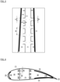
- the standing waves in the blade can be detuned or damped by openings in the partition walls (15) and (16) (see Fig. 2 ) These openings can be simple slots or holes (14), positioned, if possible, at the pressure maxima of the relevant standing wave. Since standing waves are defined by the spatial geometry, and in particular by the reflecting walls, the standing wave cannot escape through this measure.
- the slots and holes (14) can be designed with the dimensions C, D, E, F, G, H, and I so that they also act as Helmholtz resonators and thus have an even greater reducing effect on the standing waves.
- the number of openings can also be optimized with regard to the effect. However, requirements regarding the strength of the blade must also be taken into account here.
- the effect is further enhanced if - in the case of a standing wave in the central cavity (7) - the lateral cavities are closed by an acoustic partition (13). If the standing wave occurs in one of the lateral cavities (6) and (8), the central cavity (7) can also be acoustically closed.
- the design of the Helmholtz resonator is based on common physical relationships.
- the openings in the partition walls (15) and (16) can also be different, especially if the volumes in the cavity at the leading edge (6) and that at the trailing edge (8) differ.
- the distances A and B are determined by the pressure maxima of the standing wave. For optimal performance, the clusters should be located as close as possible to the pressure maxima of the standing wave. If more or fewer than three pressure maxima occur, the number of opening clusters can, of course, be adjusted to the pressure maxima.
- the effect of the opening can be further increased and reduced to lower frequencies if tubular connections (17) are installed between the cavities ( Fig. 5, 6 ).
- the air mass moving in the connections (17) reduces the frequency and oscillates against the standing wave (analogous to a vibration absorber for structural vibrations).
- the effect and frequency range of this measure is further enhanced if the cavities (6), (7), and/or (8) are closed and if the inner walls of the cavities are lined with acoustically porous material.
- the standing waves can be detuned, disturbed, and dissipated by additional structures in the cavities or inner chambers of the system.
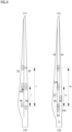
- Fig. 7 The separations shown (20), (21) and (22) result in various new standing waves with higher frequencies being created due to the shorter and irregular spacing along the length of the blade.
- these new standing waves contain less energy and thus the outward sound radiation from the blade is reduced at the new frequencies.
- the energy contained in the standing wave is further reduced by placing the separation at an angle to the longitudinal axis and thus to the direction of movement of the standing wave.
- Other shapes such as arrow-shaped or round separations are also conceivable, as these shapes can disperse the sound energy.
- Additional acoustically porous material (19) in the volume of the separated cavities leads to additional damping of the standing waves.
- the spacing and lengths P, Q, R, and S of these measures must be chosen so that the frequencies of the new standing waves no longer coincide with the reed's natural frequencies or the excitation frequencies. These measures are particularly suitable for damping standing waves in the frequency range below the Schröder frequency.
- a membrane absorber according to Fig. 9 (b) can be thought of as a damper whose mass, damping, and partly also stiffness are realized via a membrane. Additional stiffness and damping can be created by a cavity behind the membrane, the volume of which is partially or completely lined with porous material (e.g., glass wool).
- the membrane absorber should be positioned particularly where disturbing natural frequencies of the structure occur and the cross-section of the sheet is such that standing waves are present in the range of the disturbing frequency.
- Helmholtz resonators ( Fig. 9 (a) They have a similar effect to membrane absorbers, but consist of a cavity connected to the cavity to be dampened—here, the interior of the reed—via a precisely defined opening.
- the Helmholtz resonator is precisely tuned to the disturbing frequency.
- the cavity can be partially or completely lined or filled with damping or porous material.
- the dimensions of the cavity opening (depth, length, width, diameter) must be selected to achieve the desired frequency.
- the opening does not have to be tubular; it can also be slit-shaped, square, rectangular, or oval.
- the membrane absorbers and Helmholtz resonators should be installed where the pressure of the standing wave is highest. This is especially the case at the reflecting walls. Particularly high pressures also occur at the corners and ends of longer structures. These are ideal positions for membrane absorbers and Helmholtz resonators.
- the membrane absorbers or Helmholtz resonators mentioned above can also be designed as active systems. These active systems are designed in such a way that the membrane and Others actively control the air flow in the opening via an actuator in terms of phase, frequency, and amplitude. Microphones or appropriate devices are also required to measure the current pressure in the reed and the resonator. The data is processed using a control device, preferably electronic, which optimally controls the actuator on the membrane or opening based on the microphone measurement. This can cancel out the standing wave.
- the air in a Helmholtz resonator can be set into vibration via a loudspeaker. This allows both systems to actively cancel the standing waves.
- standing waves can also be prevented by attaching additional sound-absorbing material to the inner walls of the blades above 150 Hz. This prevents or attenuates the reflection of sound waves from the inner walls, making it more difficult for standing waves to form.
- the surface structure of the insulating material can be selected to dissipate sound waves particularly effectively, as is the case in sound-absorbing rooms.
Landscapes
- Engineering & Computer Science (AREA)
- Mechanical Engineering (AREA)
- Life Sciences & Earth Sciences (AREA)
- Sustainable Development (AREA)
- Sustainable Energy (AREA)
- Chemical & Material Sciences (AREA)
- Combustion & Propulsion (AREA)
- General Engineering & Computer Science (AREA)
- Aviation & Aerospace Engineering (AREA)
- Environmental & Geological Engineering (AREA)
- Wind Motors (AREA)
Applications Claiming Priority (1)
| Application Number | Priority Date | Filing Date | Title |
|---|---|---|---|
| EP23020530 | 2023-11-29 |
Publications (1)
| Publication Number | Publication Date |
|---|---|
| EP4563809A1 true EP4563809A1 (fr) | 2025-06-04 |
Family
ID=89030039
Family Applications (1)
| Application Number | Title | Priority Date | Filing Date |
|---|---|---|---|
| EP24214765.0A Pending EP4563809A1 (fr) | 2023-11-29 | 2024-11-22 | Structures de profil aérodynamique à bruit réduit |
Country Status (1)
| Country | Link |
|---|---|
| EP (1) | EP4563809A1 (fr) |
Citations (3)
| Publication number | Priority date | Publication date | Assignee | Title |
|---|---|---|---|---|
| DE102007046253A1 (de) | 2006-09-29 | 2008-04-03 | General Electric Co. | Windkraftanlagen-Rotorblatt mit Akustikverkleidung |
| US20090232658A1 (en) * | 2008-03-17 | 2009-09-17 | Brandon Gerber | Blade having a damping element and method of fabricating same |
| US20170369147A1 (en) * | 2014-12-18 | 2017-12-28 | Bombardier Inc. | Sound absorbers for airframe components |
-
2024
- 2024-11-22 EP EP24214765.0A patent/EP4563809A1/fr active Pending
Patent Citations (3)
| Publication number | Priority date | Publication date | Assignee | Title |
|---|---|---|---|---|
| DE102007046253A1 (de) | 2006-09-29 | 2008-04-03 | General Electric Co. | Windkraftanlagen-Rotorblatt mit Akustikverkleidung |
| US20090232658A1 (en) * | 2008-03-17 | 2009-09-17 | Brandon Gerber | Blade having a damping element and method of fabricating same |
| US20170369147A1 (en) * | 2014-12-18 | 2017-12-28 | Bombardier Inc. | Sound absorbers for airframe components |
Similar Documents
| Publication | Publication Date | Title |
|---|---|---|
| DE60122779T2 (de) | Fluiddruckbeaufschlagungsvorrichtung | |
| DE60112856T2 (de) | Dämpfungsstruktur und anwendungen | |
| DE69602966T2 (de) | Aktive akustische dämpfungsanordnung zur anordnung innerhalb eines rohres,insbesondere zur schalldämpfung eines belüftungs- und/oder klimanetzwerks | |
| DE102007046253A1 (de) | Windkraftanlagen-Rotorblatt mit Akustikverkleidung | |
| WO2022214316A1 (fr) | Composant composite insonorisant avec une âme en nid d'abeilles, et procédé de production de celui-ci | |
| DE112011104532T5 (de) | Schalldämpfungsvorrichtung für ein Fahrzeug | |
| EP1715189A1 (fr) | Silencieux développé pour et destiné à un compresseur | |
| DE102013208455A1 (de) | Geräuscharmes Hydraulikaggregat | |
| DE102017206079A1 (de) | Körperschallaktuator für ein Kraftfahrzeug und Kraftfahrzeug | |
| WO1998033050A1 (fr) | Tunnel de soufflerie | |
| DE102010039463A1 (de) | Gehäuse für eine Elektromaschine | |
| EP3935624B1 (fr) | Absorbeur acoustique, structure et utilisation d'un absorbeur acoustique | |
| WO2006086950A1 (fr) | Dispositif de couplage sonore entre une conduite d'admission et / ou un compartiment-moteur et l'habitacle d'un vehicule a moteur | |
| DE102008011087A1 (de) | Luftansauggehäuse mit einer perforierten Schalldämpfungswand | |
| DE2911849B2 (de) | Akustisches Gerät | |
| DE102019106685B4 (de) | Schallabsorber mit einem Helmholtz-Resonator | |
| DE102015215454A1 (de) | Vorrichtung zur Dämpfung von Schall mit einer bekannten Frequenz und einer Amplitude, Kühlungssystem sowie elektrische Anlage mit der Vorrichtung | |
| DE102012100697A1 (de) | Anordnung zur Geräuschminderung für eine große elektrische Maschine | |
| EP3246479B1 (fr) | Unité d'absorption de sons | |
| EP3529131B1 (fr) | Élément d'absorption d'énergie pour un châssis d'un véhicule automobile en tant que volume de résonance et véhicule automobile | |
| DE102018203815A1 (de) | Verfahren zur Reduktion der Schallabstrahlung einer Klimaanlage eines Fahrzeugs, schallarme Klimaanlage eines Fahrzeugs und Verwendung einer Dämmungsvorrichtung | |
| EP4073365A1 (fr) | Système de rotor pour un aéronef | |
| DE102019208743A1 (de) | Schallabsorber | |
| DE19606830A1 (de) | Vorrichtung zur Minderung der Abstrahlung und/oder Ausbreitung von Schallwellen, insbesondere im tieffrequenten und Infraschallbereich | |
| DE102017207205B4 (de) | Tragstruktur mit einem als Resonanzraum genutzten Strukturhohlraum einer Strukturkammer und Kraftfahrzeug |
Legal Events
| Date | Code | Title | Description |
|---|---|---|---|
| PUAI | Public reference made under article 153(3) epc to a published international application that has entered the european phase |
Free format text: ORIGINAL CODE: 0009012 |
|
| STAA | Information on the status of an ep patent application or granted ep patent |
Free format text: STATUS: THE APPLICATION HAS BEEN PUBLISHED |
|
| AK | Designated contracting states |
Kind code of ref document: A1 Designated state(s): AL AT BE BG CH CY CZ DE DK EE ES FI FR GB GR HR HU IE IS IT LI LT LU LV MC ME MK MT NL NO PL PT RO RS SE SI SK SM TR |
|
| STAA | Information on the status of an ep patent application or granted ep patent |
Free format text: STATUS: REQUEST FOR EXAMINATION WAS MADE |
|
| 17P | Request for examination filed |
Effective date: 20251201 |