EP4563863A1 - Collier de serrage modulaire - Google Patents
Collier de serrage modulaire Download PDFInfo
- Publication number
- EP4563863A1 EP4563863A1 EP24213950.9A EP24213950A EP4563863A1 EP 4563863 A1 EP4563863 A1 EP 4563863A1 EP 24213950 A EP24213950 A EP 24213950A EP 4563863 A1 EP4563863 A1 EP 4563863A1
- Authority
- EP
- European Patent Office
- Prior art keywords
- body portion
- mounting
- bracket
- retention clip
- latching member
- Prior art date
- Legal status (The legal status is an assumption and is not a legal conclusion. Google has not performed a legal analysis and makes no representation as to the accuracy of the status listed.)
- Pending
Links
Images



Classifications
-
- F—MECHANICAL ENGINEERING; LIGHTING; HEATING; WEAPONS; BLASTING
- F16—ENGINEERING ELEMENTS AND UNITS; GENERAL MEASURES FOR PRODUCING AND MAINTAINING EFFECTIVE FUNCTIONING OF MACHINES OR INSTALLATIONS; THERMAL INSULATION IN GENERAL
- F16L—PIPES; JOINTS OR FITTINGS FOR PIPES; SUPPORTS FOR PIPES, CABLES OR PROTECTIVE TUBING; MEANS FOR THERMAL INSULATION IN GENERAL
- F16L3/00—Supports for pipes, cables or protective tubing, e.g. hangers, holders, clamps, cleats, clips, brackets
- F16L3/08—Supports for pipes, cables or protective tubing, e.g. hangers, holders, clamps, cleats, clips, brackets substantially surrounding the pipe, cable or protective tubing
- F16L3/10—Supports for pipes, cables or protective tubing, e.g. hangers, holders, clamps, cleats, clips, brackets substantially surrounding the pipe, cable or protective tubing divided, i.e. with two members engaging the pipe, cable or protective tubing
- F16L3/1075—Supports for pipes, cables or protective tubing, e.g. hangers, holders, clamps, cleats, clips, brackets substantially surrounding the pipe, cable or protective tubing divided, i.e. with two members engaging the pipe, cable or protective tubing with two members, the two members being joined with a hinge on one side and fastened together on the other side
-
- F—MECHANICAL ENGINEERING; LIGHTING; HEATING; WEAPONS; BLASTING
- F16—ENGINEERING ELEMENTS AND UNITS; GENERAL MEASURES FOR PRODUCING AND MAINTAINING EFFECTIVE FUNCTIONING OF MACHINES OR INSTALLATIONS; THERMAL INSULATION IN GENERAL
- F16L—PIPES; JOINTS OR FITTINGS FOR PIPES; SUPPORTS FOR PIPES, CABLES OR PROTECTIVE TUBING; MEANS FOR THERMAL INSULATION IN GENERAL
- F16L3/00—Supports for pipes, cables or protective tubing, e.g. hangers, holders, clamps, cleats, clips, brackets
- F16L3/08—Supports for pipes, cables or protective tubing, e.g. hangers, holders, clamps, cleats, clips, brackets substantially surrounding the pipe, cable or protective tubing
- F16L3/10—Supports for pipes, cables or protective tubing, e.g. hangers, holders, clamps, cleats, clips, brackets substantially surrounding the pipe, cable or protective tubing divided, i.e. with two members engaging the pipe, cable or protective tubing
- F16L3/1033—Supports for pipes, cables or protective tubing, e.g. hangers, holders, clamps, cleats, clips, brackets substantially surrounding the pipe, cable or protective tubing divided, i.e. with two members engaging the pipe, cable or protective tubing with two members engaging the pipe, cable or tubing, the two members being joined only on one side of the pipe
-
- F—MECHANICAL ENGINEERING; LIGHTING; HEATING; WEAPONS; BLASTING
- F16—ENGINEERING ELEMENTS AND UNITS; GENERAL MEASURES FOR PRODUCING AND MAINTAINING EFFECTIVE FUNCTIONING OF MACHINES OR INSTALLATIONS; THERMAL INSULATION IN GENERAL
- F16L—PIPES; JOINTS OR FITTINGS FOR PIPES; SUPPORTS FOR PIPES, CABLES OR PROTECTIVE TUBING; MEANS FOR THERMAL INSULATION IN GENERAL
- F16L3/00—Supports for pipes, cables or protective tubing, e.g. hangers, holders, clamps, cleats, clips, brackets
- F16L3/08—Supports for pipes, cables or protective tubing, e.g. hangers, holders, clamps, cleats, clips, brackets substantially surrounding the pipe, cable or protective tubing
- F16L3/10—Supports for pipes, cables or protective tubing, e.g. hangers, holders, clamps, cleats, clips, brackets substantially surrounding the pipe, cable or protective tubing divided, i.e. with two members engaging the pipe, cable or protective tubing
-
- B—PERFORMING OPERATIONS; TRANSPORTING
- B60—VEHICLES IN GENERAL
- B60R—VEHICLES, VEHICLE FITTINGS, OR VEHICLE PARTS, NOT OTHERWISE PROVIDED FOR
- B60R16/00—Electric or fluid circuits specially adapted for vehicles and not otherwise provided for; Arrangement of elements of electric or fluid circuits specially adapted for vehicles and not otherwise provided for
- B60R16/02—Electric or fluid circuits specially adapted for vehicles and not otherwise provided for; Arrangement of elements of electric or fluid circuits specially adapted for vehicles and not otherwise provided for electric constitutive elements
- B60R16/0207—Wire harnesses
- B60R16/0215—Protecting, fastening and routing means therefor
-
- B—PERFORMING OPERATIONS; TRANSPORTING
- B60—VEHICLES IN GENERAL
- B60R—VEHICLES, VEHICLE FITTINGS, OR VEHICLE PARTS, NOT OTHERWISE PROVIDED FOR
- B60R16/00—Electric or fluid circuits specially adapted for vehicles and not otherwise provided for; Arrangement of elements of electric or fluid circuits specially adapted for vehicles and not otherwise provided for
- B60R16/08—Electric or fluid circuits specially adapted for vehicles and not otherwise provided for; Arrangement of elements of electric or fluid circuits specially adapted for vehicles and not otherwise provided for fluid
-
- F—MECHANICAL ENGINEERING; LIGHTING; HEATING; WEAPONS; BLASTING
- F16—ENGINEERING ELEMENTS AND UNITS; GENERAL MEASURES FOR PRODUCING AND MAINTAINING EFFECTIVE FUNCTIONING OF MACHINES OR INSTALLATIONS; THERMAL INSULATION IN GENERAL
- F16L—PIPES; JOINTS OR FITTINGS FOR PIPES; SUPPORTS FOR PIPES, CABLES OR PROTECTIVE TUBING; MEANS FOR THERMAL INSULATION IN GENERAL
- F16L3/00—Supports for pipes, cables or protective tubing, e.g. hangers, holders, clamps, cleats, clips, brackets
- F16L3/08—Supports for pipes, cables or protective tubing, e.g. hangers, holders, clamps, cleats, clips, brackets substantially surrounding the pipe, cable or protective tubing
- F16L3/10—Supports for pipes, cables or protective tubing, e.g. hangers, holders, clamps, cleats, clips, brackets substantially surrounding the pipe, cable or protective tubing divided, i.e. with two members engaging the pipe, cable or protective tubing
- F16L3/1058—Supports for pipes, cables or protective tubing, e.g. hangers, holders, clamps, cleats, clips, brackets substantially surrounding the pipe, cable or protective tubing divided, i.e. with two members engaging the pipe, cable or protective tubing one member being flexible or elastic
-
- F—MECHANICAL ENGINEERING; LIGHTING; HEATING; WEAPONS; BLASTING
- F16—ENGINEERING ELEMENTS AND UNITS; GENERAL MEASURES FOR PRODUCING AND MAINTAINING EFFECTIVE FUNCTIONING OF MACHINES OR INSTALLATIONS; THERMAL INSULATION IN GENERAL
- F16L—PIPES; JOINTS OR FITTINGS FOR PIPES; SUPPORTS FOR PIPES, CABLES OR PROTECTIVE TUBING; MEANS FOR THERMAL INSULATION IN GENERAL
- F16L3/00—Supports for pipes, cables or protective tubing, e.g. hangers, holders, clamps, cleats, clips, brackets
- F16L3/08—Supports for pipes, cables or protective tubing, e.g. hangers, holders, clamps, cleats, clips, brackets substantially surrounding the pipe, cable or protective tubing
- F16L3/12—Supports for pipes, cables or protective tubing, e.g. hangers, holders, clamps, cleats, clips, brackets substantially surrounding the pipe, cable or protective tubing comprising a member substantially surrounding the pipe, cable or protective tubing
- F16L3/13—Supports for pipes, cables or protective tubing, e.g. hangers, holders, clamps, cleats, clips, brackets substantially surrounding the pipe, cable or protective tubing comprising a member substantially surrounding the pipe, cable or protective tubing and engaging it by snap action
-
- H—ELECTRICITY
- H02—GENERATION; CONVERSION OR DISTRIBUTION OF ELECTRIC POWER
- H02G—INSTALLATION OF ELECTRIC CABLES OR LINES, OR OF COMBINED OPTICAL AND ELECTRIC CABLES OR LINES
- H02G3/00—Installations of electric cables or lines or protective tubing therefor in or on buildings, equivalent structures or vehicles
- H02G3/02—Details
- H02G3/04—Protective tubing or conduits, e.g. cable ladders or cable troughs
- H02G3/0456—Ladders or other supports
-
- H—ELECTRICITY
- H02—GENERATION; CONVERSION OR DISTRIBUTION OF ELECTRIC POWER
- H02G—INSTALLATION OF ELECTRIC CABLES OR LINES, OR OF COMBINED OPTICAL AND ELECTRIC CABLES OR LINES
- H02G3/00—Installations of electric cables or lines or protective tubing therefor in or on buildings, equivalent structures or vehicles
- H02G3/30—Installations of cables or lines on walls, floors or ceilings
- H02G3/32—Installations of cables or lines on walls, floors or ceilings using mounting clamps
Definitions
- This disclosure is generally directed to retention clips for mounting cables, wires, tubes, or pipes to a support structure, such as a vehicle body.
- retention clips have been devised to mount elongated parts, such as a fuel or brake line, accelerator cable, wire harness, to a vehicle frame at prescribed structural locations.
- the retention clips which are unitary members typically include two portions, one being a body portion for receiving and retaining the article to be held and the other a bracket portion used to mount the retention clip to the vehicle body.
- the body portion of such retention clips use pivotal covers which lock over an article inserted into the article holder or snap type arms which automatically hold an article on the retention clip after insertion past the arms. The arms bend apart on insertion and then snap back to engage a small width or diameter portion of the article and forcibly hold the article.
- the body portion of the retention clips can also employ vibration absorbing material or vibration blocking features to isolate vibrations in the pipes, tubes, or harnesses from being coupled to the bracket portion and inducing unwanted noise to the vehicle frame.
- the vibration absorbing feature is typically provided by vibration absorbing materials mounted in the body portion of the retention clip.
- the vibration damping materials are typically formed as a separate part conforming to the body portion of the retention clip and then inserted into the body portion. This increases part count and overall retention clip cost due to the added assembly steps and assembly time.
- the vibration absorbing material is injection molded in a second process or "shot" of a two-shot process to complete the formation of the vibration damping material of the retention clip.
- retention clips are manufactured using various bracket configurations
- a two-shot process that manufactures a retention clip consisting of a retention body and a bracket requires many different molding steps to complete different configurations of retention clips.
- the two-shot method also becomes costly to manufacture due to the requirement to mold retention clips with integral brackets of various configurations.
- This disclosure relates to retention clips for mounting elongated articles to a support structure, such as a vehicle body .
- a retention clip comprising a clamping body having a first body portion rotatably mounted to a second body portion.
- First and second isolation portions are attached to respective first and second body portions, wherein rotation of the first body portion over the second body portion causes the first isolation portion to rotate over the second isolation portion.
- At least a first mounting pin extends from a mounting surface of the second body portion. The first mounting pin is arranged to be accepted in a first hole in a bracket and the mounting pin physically altered to fix the clamping body to the bracket.
- the present disclosure is a modular retention clip consisting of a clamping body for mounting elongated articles, such as wires, harnesses, pipes, tubes, etc., that is mountable to different brackets and that can be used in an automotive application.
- the assembly of the clamping body to a bracket forms a modular retention clip that can be fastened to a vehicle frame.
- the clamping body includes first and second body portions both created of a first rigid polymeric material.
- the body portions when angularly rotated apart with respect to each other define an open position, and when rotated into direct contact with each other define an engaged position.
- An isolation portion is created of a resilient second polymeric material.
- the isolation portion includes isolation members individually connected to each of the first and second body portions. The isolation members are positioned facing each other when the retention clip is in the engaged position. The isolation members frictionally contact and thereby retain the elongated articles in the engaged position.
- a living hinge integrally connects the body portions together, allowing the body portions to rotate with respect to each other. The living hinge provides the only connection between the first and second body portions as the body portions transition between the open position and the engaged position.
- the clamping body further includes a pair of mounting members extending from a surface of the second body portion of the clamping body. Each mounting member is arranged to be placed within a respective hole formed through a mounting bracket. Each mounting member is deformable using heat and a tool to form a retention head that fixes the clamping body to the bracket.
- the bracket may be manufactured in various arrangements and forms. All the brackets are arranged to accept the clamping body to form the modular retention clip.
- the retention clip includes a clamping body 10 composed of a polymeric first material such as a polyamide material, or a polyoxymethylene material, or other similar thermoplastic material having a stiffness necessary to retain the shape of the retention clip when the clip is engaged with one or more elongated articles (not shown).
- the clamping body 10 is made in a first injection molding process or "shot” in a mold cavity (not shown).
- the clamping body 10 can further include an isolation portion 12 which is made of a resilient second material such as for example a thermoplastic elastomer.
- the isolation portion 12 is injection molded in a second process or in a two-shot process to complete the formation of the clamping body 10.
- the materials of clamping body 10 and isolation portion 12 are fixedly joined while the materials are at an elevated temperature in the mold such as by a chemical bond acting to join the isolation portion 12 to clamping body 10.
- Clamping body 10 includes a first body portion 16 which is rotatably connected to a second body portion 18. Material of the isolation portion 12 when injected in the second molding shot flows onto first body portion 16 to create a first isolation member 20 having a plurality of resilient ribs 22 extending from a clamping surface and a second isolation member 24 having a plurality of resilient ribs 26 extending from a complementary clamping surface.
- a living hinge 30 flexibly connects the second body portion 18 to the first body portion 16.
- Living hinge 30 is integrally and homogeneously made of the material of the clamping body 10 and created during injection molding of the first and second portions 16 and 18.
- the material of living hinge 30 extends between an exterior surface 32 of portion 16 to an exterior surface 34 of portion 18.
- the first and second body portions 16, 18 are molded following the first molding shot having portions 16, 18 integrally connected to living hinge 30.
- the material of isolation portion 12 flows to the first body portion 16 toward an arc-shaped surface 41 and to a similar arc-shaped surface 42 of the second body portion 18.
- the first body portion 16 of clamping body 10 further includes a latching member 36 which elastically deflects to be engaged within a latch receiving cavity 38 created in the second body portion 18 to assist in coupling the first and second body portions 16, 18 together.
- the latching member 36 includes a flexible arm 44 extending from the material of the first body portion 16 towards the receiving cavity 38.
- the receiving cavity 38 is formed between a rigid wall 40 extending from material of the second body portion 18 and a deflecting arm 43 that elastically deflects toward rigid wall 40.
- As arm 44 of latching member 36 is received in the latch receiving cavity 38 a tooth 47 extending from arm 44 engages a complementary tooth 46 extending into receiving cavity 38 from wall 40 after the arm 44 extends through the receiving cavity 38.
- Deflecting arm 43 applies a force against arm 44 when tooth 46 couples to tooth 47 that resists the release of arm 44 from receiving cavity 38.
- First and second mounting pins 50 and 52 extend from the bottom surface of the second body 18.
- the mounting pins 50, 52 are cylindrical in cross section and each have a cavity 53 extending partially through the mounting pins 50 and 52.
- Each mounting pin 50, 52 is offset axially from the other in order to maximize the distance between the pins which aids in the stability of the mounting arrangement and the retention of clamping member to a bracket.
- the mounting pins 50, 52 are arranged to fit within complementary holes in a bracket and fixed to the bracket using a heat staking process which will be explained in more detail below.
- the clamping body 10 is molded using the two-shot molding process in the open position shown in FIG. 1
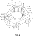
- the first body portion 16 is shown in an engaged with the second body portion 18.
- the body portions 16 and 18 are engaged preferably before but also optionally after receipt of elongated articles within isolation portion 12 such as wires, harnesses, pipes, tubes, (not shown) and prior to the clamping body 10 being fixed to a bracket 60.
- the mounting of the clamping body 10 to a bracket 60 will be shown in greater detail with reference to FIGS. 3A-3B .
- the elongated articles are placed between isolation members 20 and 24 and rested on either isolation member 20 or 24 based on the orientation of the clamping body 10.
- the first body portion 16 is then rotated from the as molded or open position shown with respect to FIG. 1 toward the closed or engaged position shown in FIG. 2 .
- the axis of rotation is defined by a closing arc defined by the living hinge 30.
- the living hinge 30 provides the only physical connection between the second body portion 18 and first body portion 16.
- the freely deflectable material of living hinge 30 provides an elastic biasing force that acts to align and bring the first body portion 16 over the second body portion 18 and the elongated articles contained between isolation members 20 and 24.
- the resilient ribs 22, 26 of the first and second isolation members 20, 24 elastically compress, or bend as the elongated articles are received on the isolation members.
- the second body portion 18 is coupled to the first body portion 16 by arm 44 of latching member 36, when arm 44 is received in cavity 38 and locked together by the engagement of tooth 47 with tooth 46.
- FIGS. 3A and 3B show the clamping body 10 in the engaged position fixed to an exemplary mounting bracket 60.
- FIGS 4A and 4B show the exemplary mounting bracket 60 without the clamping body 10 fixed to the mounting bracket 60.
- the bracket 60 is comprised of a clamping body receiving portion 62 and a mounting portion 64 joined in an axial orientation to the other.
- FIG. 4A illustrates a first side of the bracket 60 while FIG 4B illustrates a second side of the bracket 60 opposite from the first side.
- the clamping body receiving portion 62 is formed on the first side of bracket 60 by a planar mounting surface 65 bordered by a pair of walls 66 located on a perimeter edge of mounting surface 65 with each wall 66 directly opposite from the other.
- the mounting portion 64 of bracket 60 comprises a raised platform extending from mounting surface 65 from a perimeter wall 67 extending vertically from a third perimeter edge of mounting surface 65.
- Mounting portion 64 includes a centrally located mounting hole 69 extending through the platform from the first side of the mounting bracket 60 to the second side.
- the mounting surface 65 further includes first and second holes 61 and 68 that extend through mounting surface 65 on the first side of bracket 60 to a surface 71 on the second side of bracket 60.
- the holes 61 and 68 are sized and located on mounting surface 65 to accept therethrough the mounting pins 50, 52 of the clamping body 10. As can be easily seen, the mounting holes 61 and 68 are axially offset on the mounting surface 65 to match the offset arrangement of mounting pins 50 and 52 of the clamping body 10.
- FIG. 3A illustrates the clamping body 10 in the engaged position, it will be appreciated that the clamping body 10 can also be installed to the bracket 60 in the as-molded or open position and rotated into the engaged position after mounting of the clamping body 10 to the bracket 60.
- the clamping body 10 is fixed to the bracket 60 by applying heat from a heat source to pins 50 and 52 from the second side of the bracket 60 to soften the polymeric material of the mounting pins 50, 52.
- the mounting pins 50, 52 are pressed down against a surface 71 of the second side of bracket 60 to form the domed caps 70, 72 against surface 71. Once cooled, the domed caps 70, 72 fix and retain the clamping body 10 to bracket 60 as shown in FIG 3B .
- the completed retention clip can then be fastened to a vehicle frame or other structure by using a fastener (not shown) introduced into mounting hole 69 that is accepted by an associated fastener receiver on the vehicle frame.
- the second side of bracket 60 may also include a key member 75 that fits within an associated recess in the vehicle frame to properly locate the bracket 60 on the vehicle frame and aid in fastening of the bracket 60.
- FIGS. 5A-5B and 6A-B illustrate examples of other forms of bracket 60 that can be used with clamping body 10 to form the modular retention clip of the present disclosure. It should be noted that all the brackets 60 illustrated in FIGS. 4A-4B , 5A-5B and 6A-6B can be molded from a polymeric material separately from the clamping body 10 or stamped from a suitable metal material. Each of the brackets 60 illustrated in FIGS. 5A-5B and 6A-6B comprise the same major components as illustrated and explained for the bracket 60 of FIGS. 4A-4B .
- FIGS. 5A and 6A illustrates the first side of the bracket 60 while FIGS. 5B and 6B illustrates the second side of the bracket 60 opposite from the first side. As can be seen in FIGS.
- the bracket 60 in this exemplary bracket discloses a configuration that has a mounting portion 64 located at an angular orientation of 45 degrees from the receiving potion 62.
- the mounting portion 64 is located 90 degrees from the receiving portion 62.
- each bracket 60 has common mounting features including the planar mounting surface 65, second surface 71, walls 66 and holes 61 and 68.
- the common mounting features providing a modularity wherein a clamping body 10 can be assembled on a various types and configuration of brackets 60 to form the modular retention clip.
- the term "communicate,” as well as derivatives thereof, encompasses both direct and indirect communication.
- the term “or” is inclusive, meaning and/or.
- the phrase “associated with,” as well as derivatives thereof, may mean to include, be included within, interconnect with, contain, be contained within, connect to or with, couple to or with, be communicable with, cooperate with, interleave, juxtapose, be proximate to, be bound to or with, have, have a property of, have a relationship to or with, or the like.
- phrases "at least one of,” when used with a list of items, means that different combinations of one or more of the listed items may be used, and only one item in the list may be needed.
- “at least one of: A, B, and C” includes any of the following combinations: A, B, C, A and B, A and C, B and C, and A and B and C.
Landscapes
- Engineering & Computer Science (AREA)
- General Engineering & Computer Science (AREA)
- Mechanical Engineering (AREA)
- Architecture (AREA)
- Civil Engineering (AREA)
- Structural Engineering (AREA)
- Clamps And Clips (AREA)
Applications Claiming Priority (1)
| Application Number | Priority Date | Filing Date | Title |
|---|---|---|---|
| US202363600733P | 2023-11-20 | 2023-11-20 |
Publications (1)
| Publication Number | Publication Date |
|---|---|
| EP4563863A1 true EP4563863A1 (fr) | 2025-06-04 |
Family
ID=93591018
Family Applications (1)
| Application Number | Title | Priority Date | Filing Date |
|---|---|---|---|
| EP24213950.9A Pending EP4563863A1 (fr) | 2023-11-20 | 2024-11-19 | Collier de serrage modulaire |
Country Status (3)
| Country | Link |
|---|---|
| US (1) | US20250164034A1 (fr) |
| EP (1) | EP4563863A1 (fr) |
| CN (1) | CN120020430A (fr) |
Families Citing this family (2)
| Publication number | Priority date | Publication date | Assignee | Title |
|---|---|---|---|---|
| US20240353028A1 (en) * | 2023-04-24 | 2024-10-24 | Tramec, L.L.C. | Clamp assembly |
| US12410826B1 (en) * | 2025-05-18 | 2025-09-09 | Terry Doerscher | Secure quick attach/detach clip |
Citations (4)
| Publication number | Priority date | Publication date | Assignee | Title |
|---|---|---|---|---|
| CN201554733U (zh) * | 2009-11-27 | 2010-08-18 | 丽清汽车科技(上海)有限公司 | 塑料热熔铆钉 |
| US20130001373A1 (en) * | 2010-01-27 | 2013-01-03 | Nifco Inc. | Clamp |
| CN106641455A (zh) * | 2017-02-27 | 2017-05-10 | 上海易扣精密件制造有限公司 | 便装式汽车空调系统防噪音卡箍 |
| FR3119004A1 (fr) * | 2021-01-21 | 2022-07-22 | Psa Automobiles Sa | Système de fixation de conduit |
Family Cites Families (6)
| Publication number | Priority date | Publication date | Assignee | Title |
|---|---|---|---|---|
| JP2004242478A (ja) * | 2003-02-10 | 2004-08-26 | Nippon Pop Rivets & Fasteners Ltd | ケーブルクランプ |
| DE102006026250A1 (de) * | 2006-06-06 | 2007-12-13 | BSH Bosch und Siemens Hausgeräte GmbH | Klammerelement zum Halten zumindest eines Gegenstands, insbesondere eines Kabels |
| JP2010133543A (ja) * | 2008-12-08 | 2010-06-17 | Nippon Pop Rivets & Fasteners Ltd | コルゲートチューブのクランプ |
| US7887012B2 (en) * | 2009-03-31 | 2011-02-15 | Denso International America, Inc. | Insert for tube retaining bracket |
| US8967556B2 (en) * | 2012-03-13 | 2015-03-03 | Newfrey Llc | Two shot tube retention clip with resilient living hinge |
| US11440362B2 (en) * | 2018-11-15 | 2022-09-13 | John Wesley Nicholson | Universal mounting clamps system and method |
-
2024
- 2024-11-08 US US18/941,374 patent/US20250164034A1/en active Pending
- 2024-11-19 EP EP24213950.9A patent/EP4563863A1/fr active Pending
- 2024-11-20 CN CN202411660356.8A patent/CN120020430A/zh active Pending
Patent Citations (4)
| Publication number | Priority date | Publication date | Assignee | Title |
|---|---|---|---|---|
| CN201554733U (zh) * | 2009-11-27 | 2010-08-18 | 丽清汽车科技(上海)有限公司 | 塑料热熔铆钉 |
| US20130001373A1 (en) * | 2010-01-27 | 2013-01-03 | Nifco Inc. | Clamp |
| CN106641455A (zh) * | 2017-02-27 | 2017-05-10 | 上海易扣精密件制造有限公司 | 便装式汽车空调系统防噪音卡箍 |
| FR3119004A1 (fr) * | 2021-01-21 | 2022-07-22 | Psa Automobiles Sa | Système de fixation de conduit |
Also Published As
| Publication number | Publication date |
|---|---|
| CN120020430A (zh) | 2025-05-20 |
| US20250164034A1 (en) | 2025-05-22 |
Similar Documents
| Publication | Publication Date | Title |
|---|---|---|
| EP4563863A1 (fr) | Collier de serrage modulaire | |
| KR100374164B1 (ko) | 차양판클립조립체와리벳형파스너 | |
| MXPA96005233A (en) | Means to hold a module of a bag of a | |
| JP3628945B2 (ja) | サンバイザーホルダー | |
| US5494245A (en) | Wiring harness retainer clip | |
| EP1937538B1 (fr) | Ensemble de positionnement | |
| JP3947617B2 (ja) | 防振保持具 | |
| US6347872B1 (en) | Snap-in rearview mirror assembly for vehicles | |
| JP5553901B2 (ja) | 構成部材支持体 | |
| US20090249587A1 (en) | Vehicle clip centering device and method | |
| JP2014047839A (ja) | 防振クランプ | |
| CN115388071A (zh) | 用于将构件紧固到载体构件上的装置 | |
| US20080057768A1 (en) | Connector unit | |
| US5597280A (en) | Locking clip with resilient barb arm | |
| JP2020524777A5 (fr) | ||
| CN115027373B (zh) | 被适配为安装到机动车辆的窗玻璃的支架 | |
| CN103502548A (zh) | 把手基座的安装构造 | |
| US7338314B2 (en) | Electrical wire routing connector presenter bracket | |
| US7435092B2 (en) | Retainer harness clip apparatus | |
| US20230118668A1 (en) | Fastening strap clamp assembly | |
| CN111824041B (zh) | 用于固定两个元件以允许其预组装的装置 | |
| KR101779869B1 (ko) | 일체화된 관 앵커를 갖는 소켓 조인트 | |
| JP2500227Y2 (ja) | 隠しクリップ | |
| US7351001B1 (en) | Pillar shield for securing a wire harness | |
| EP3722156B1 (fr) | Ensemble pince |
Legal Events
| Date | Code | Title | Description |
|---|---|---|---|
| PUAI | Public reference made under article 153(3) epc to a published international application that has entered the european phase |
Free format text: ORIGINAL CODE: 0009012 |
|
| STAA | Information on the status of an ep patent application or granted ep patent |
Free format text: STATUS: THE APPLICATION HAS BEEN PUBLISHED |
|
| AK | Designated contracting states |
Kind code of ref document: A1 Designated state(s): AL AT BE BG CH CY CZ DE DK EE ES FI FR GB GR HR HU IE IS IT LI LT LU LV MC ME MK MT NL NO PL PT RO RS SE SI SK SM TR |
|
| STAA | Information on the status of an ep patent application or granted ep patent |
Free format text: STATUS: REQUEST FOR EXAMINATION WAS MADE |
|
| 17P | Request for examination filed |
Effective date: 20251125 |