EP4563876A1 - Ensemble boîtier et capuchon pour détecteur de fuite de fluide de tuyau marin et système de détection de fuite de fluide de tuyau marin - Google Patents
Ensemble boîtier et capuchon pour détecteur de fuite de fluide de tuyau marin et système de détection de fuite de fluide de tuyau marin Download PDFInfo
- Publication number
- EP4563876A1 EP4563876A1 EP22953212.2A EP22953212A EP4563876A1 EP 4563876 A1 EP4563876 A1 EP 4563876A1 EP 22953212 A EP22953212 A EP 22953212A EP 4563876 A1 EP4563876 A1 EP 4563876A1
- Authority
- EP
- European Patent Office
- Prior art keywords
- cap
- radio wave
- portions
- casing
- projection portions
- Prior art date
- Legal status (The legal status is an assumption and is not a legal conclusion. Google has not performed a legal analysis and makes no representation as to the accuracy of the status listed.)
- Pending
Links
Images


Classifications
-
- F—MECHANICAL ENGINEERING; LIGHTING; HEATING; WEAPONS; BLASTING
- F16—ENGINEERING ELEMENTS AND UNITS; GENERAL MEASURES FOR PRODUCING AND MAINTAINING EFFECTIVE FUNCTIONING OF MACHINES OR INSTALLATIONS; THERMAL INSULATION IN GENERAL
- F16L—PIPES; JOINTS OR FITTINGS FOR PIPES; SUPPORTS FOR PIPES, CABLES OR PROTECTIVE TUBING; MEANS FOR THERMAL INSULATION IN GENERAL
- F16L11/00—Hoses, i.e. flexible pipes
- F16L11/04—Hoses, i.e. flexible pipes made of rubber or flexible plastics
- F16L11/12—Hoses, i.e. flexible pipes made of rubber or flexible plastics with arrangements for particular purposes, e.g. specially profiled, with protecting layer, heated, electrically conducting
- F16L11/133—Hoses, i.e. flexible pipes made of rubber or flexible plastics with arrangements for particular purposes, e.g. specially profiled, with protecting layer, heated, electrically conducting buoyant
-
- G—PHYSICS
- G01—MEASURING; TESTING
- G01L—MEASURING FORCE, STRESS, TORQUE, WORK, MECHANICAL POWER, MECHANICAL EFFICIENCY, OR FLUID PRESSURE
- G01L19/00—Details of, or accessories for, apparatus for measuring steady or quasi-steady pressure of a fluent medium insofar as such details or accessories are not special to particular types of pressure gauges
- G01L19/08—Means for indicating or recording, e.g. for remote indication
- G01L19/086—Means for indicating or recording, e.g. for remote indication for remote indication
-
- G—PHYSICS
- G01—MEASURING; TESTING
- G01M—TESTING STATIC OR DYNAMIC BALANCE OF MACHINES OR STRUCTURES; TESTING OF STRUCTURES OR APPARATUS, NOT OTHERWISE PROVIDED FOR
- G01M3/00—Investigating fluid-tightness of structures
- G01M3/02—Investigating fluid-tightness of structures by using fluid or vacuum
- G01M3/26—Investigating fluid-tightness of structures by using fluid or vacuum by measuring rate of loss or gain of fluid, e.g. by pressure-responsive devices, by flow detectors
- G01M3/28—Investigating fluid-tightness of structures by using fluid or vacuum by measuring rate of loss or gain of fluid, e.g. by pressure-responsive devices, by flow detectors for pipes, cables or tubes; for pipe joints or seals; for valves ; for welds
- G01M3/2807—Investigating fluid-tightness of structures by using fluid or vacuum by measuring rate of loss or gain of fluid, e.g. by pressure-responsive devices, by flow detectors for pipes, cables or tubes; for pipe joints or seals; for valves ; for welds for pipes
- G01M3/2815—Investigating fluid-tightness of structures by using fluid or vacuum by measuring rate of loss or gain of fluid, e.g. by pressure-responsive devices, by flow detectors for pipes, cables or tubes; for pipe joints or seals; for valves ; for welds for pipes using pressure measurements
-
- G—PHYSICS
- G01—MEASURING; TESTING
- G01M—TESTING STATIC OR DYNAMIC BALANCE OF MACHINES OR STRUCTURES; TESTING OF STRUCTURES OR APPARATUS, NOT OTHERWISE PROVIDED FOR
- G01M3/00—Investigating fluid-tightness of structures
- G01M3/02—Investigating fluid-tightness of structures by using fluid or vacuum
- G01M3/26—Investigating fluid-tightness of structures by using fluid or vacuum by measuring rate of loss or gain of fluid, e.g. by pressure-responsive devices, by flow detectors
- G01M3/28—Investigating fluid-tightness of structures by using fluid or vacuum by measuring rate of loss or gain of fluid, e.g. by pressure-responsive devices, by flow detectors for pipes, cables or tubes; for pipe joints or seals; for valves ; for welds
- G01M3/2807—Investigating fluid-tightness of structures by using fluid or vacuum by measuring rate of loss or gain of fluid, e.g. by pressure-responsive devices, by flow detectors for pipes, cables or tubes; for pipe joints or seals; for valves ; for welds for pipes
- G01M3/283—Investigating fluid-tightness of structures by using fluid or vacuum by measuring rate of loss or gain of fluid, e.g. by pressure-responsive devices, by flow detectors for pipes, cables or tubes; for pipe joints or seals; for valves ; for welds for pipes for double-walled pipes
-
- F—MECHANICAL ENGINEERING; LIGHTING; HEATING; WEAPONS; BLASTING
- F16—ENGINEERING ELEMENTS AND UNITS; GENERAL MEASURES FOR PRODUCING AND MAINTAINING EFFECTIVE FUNCTIONING OF MACHINES OR INSTALLATIONS; THERMAL INSULATION IN GENERAL
- F16L—PIPES; JOINTS OR FITTINGS FOR PIPES; SUPPORTS FOR PIPES, CABLES OR PROTECTIVE TUBING; MEANS FOR THERMAL INSULATION IN GENERAL
- F16L2201/00—Special arrangements for pipe couplings
- F16L2201/30—Detecting leaks
-
- F—MECHANICAL ENGINEERING; LIGHTING; HEATING; WEAPONS; BLASTING
- F17—STORING OR DISTRIBUTING GASES OR LIQUIDS
- F17D—PIPE-LINE SYSTEMS; PIPE-LINES
- F17D5/00—Protection or supervision of installations
- F17D5/02—Preventing, monitoring, or locating loss
- F17D5/06—Preventing, monitoring, or locating loss using electric or acoustic means
Definitions
- the present invention relates to an assembly of a casing for a fluid leakage detector for a marine hose and a cap and a fluid leakage detection system for a marine hose, and more particularly to an assembly of a casing and a cap and a fluid leakage detection system for a marine hose including the assembly that can provide improved durability of the detector and reduced risk of damage to both the detector and an object due to contact between the detector and the object and have good wireless communication with the detector.
- a fluid retention layer can communicate with a detector via a communication pipe.
- the pressure in the pressure holding chamber formed inside the casing of the detector increases through the communication pipe.
- This pressure change can be acquired by a communication unit as detected pressure data by a pressure sensor unit with the use of a return radio wave from a passive IC tag and thus is useful for reliably detecting the fluid leakage while facilitating a work for checking the fluid leakage.
- the pressure sensor unit and the IC tag are housed in the pressure holding chamber.
- the upper side of the pressure holding chamber is covered by a radio wave transmission portion.
- the radio wave transmission portion is disposed to be exposed in a protruding manner from the surface of a marine hose. Accordingly, when the marine hose is installed in the sea or collected into a ship, or when the marine hose is used in the sea, the radio wave transmission portion is more likely to be subjected to external force from a certain object and damaged thereby. Conversely, when a metal cover or the like is simply mounted around the top of the radio wave transmission portion to protect the radio wave transmission portion, good radio wave communication is impaired.
- Patent Document 1 JP 2021-46929 A
- An object of the present invention is to provide a casing and cap assembly and a fluid leakage detection system for a marine hose including the assembly that can provide improved durability of a detector and reduced risk of damage to both the detector and an object due to contact between the detector and the object and have good wireless communication with the detector.
- an assembly of a casing for a fluid leakage detector for a marine hose and a cap is an assembly of a casing for a fluid leakage detector and a cap, the casing being installed on a surface of a marine hose and communicably connected to a fluid retention layer formed in the marine hose, the cap being fixed to the casing.
- the casing includes a base portion made of metal and having a cylindrical shape, a radio wave transmission portion that watertightly blocks an upper end portion side of the base portion, and three or more projection portions made of metal and projecting from the base portion above the radio wave transmission portion and a pressure holding chamber surrounded by the base portion and the radio wave transmission portion.
- the projection portions are disposed at intervals in a circumferential direction at positions on an outer circumferential side of the radio wave transmission portion in a plan view. Upper end portions of the projection portions are separated from each other. A pressure sensor unit and a passive IC tag connected to the pressure sensor unit are accommodated in the pressure holding chamber.
- the cap is an annular body made of resin or rubber that continuously covers an upper end portion of each of the projection portions in the circumferential direction in a plan view and is formed with an engaging portion that engages with the upper end portion of each of the projection portions.
- the fluid leakage detection system for a marine hose includes: the assembly of a casing for a fluid leakage detector for a marine hose and a cap described above; a detector including the pressure sensor unit and the IC tag accommodated in the pressure holding chamber; a communication pipe extending on a surface of the marine hose and communicably connecting the fluid retention layer and the detector; a check valve allowing only a flow from a side of the communication pipe to a side of the pressure holding chamber; and a radio wave transmission unit and a radio wave reception unit disposed outside the marine hose.
- a return radio wave is transmitted from the IC tag in response to a transmission radio wave transmitted from the radio wave transmission unit.
- Detected pressure data from the pressure sensor unit is sent via the return radio wave and received by the radio wave reception unit.
- the three or more projection portions made of metal and projecting above the radio wave transmission portion are disposed at intervals in the circumferential direction at positions on the outer circumferential side of the radio wave transmission portion in a plan view, the top surface of the radio wave transmission portion is protected by these projection portions. Consequently, the risk of damage to the radio wave transmission portion is reduced, which is advantageous for improvement of the durability of the detector.
- the projection portions are disposed at intervals in the circumferential direction and the upper end portions of the projection portions are separated from each other in a plan view, and thus the disadvantage that good radio wave communication is impaired by these projection portions is avoidable.
- the upper end portions of the projection portions are covered by the cap which is an annular body made of a resin that is continuous in the circumferential direction in a plan view, and thus even if the upper end portions of the projection portions made of metal come into contact with a certain object, it is advantageous in reducing the risk of damage to both the detector and the object.
- a region on the inner circumferential side from the projection portions and a region on the outer circumferential side from the projection portions communicate with each other through a gap in the circumferential direction between the lower end portions of the projection portions adjacent in the circumferential direction, and thus the force received by the cap from the wave is reduced, which is advantageous for stably fixing the cap to the casing for a long period of time.
- the cap since the cap is an annular body, the top surface of the radio wave transmission portion is not entirely covered by the cap, and it is possible to prevent good radio wave communication with the detector from being impaired.
- the fluid leakage detection system With the fluid leakage detection system according to the embodiment of the present invention, good radio wave communication between the radio wave transmission unit and the radio wave reception unit disposed outside the marine hose and the detector (IC tag) can be maintained for a long period of time. As a result, the ease of checking and certainty of detection of the fluid leakage can be ensured for a long period of time. In addition, even if an object comes into contact with the detector, the risk of damage to both the detector and the object can be reduced for a long period of time.
- an assembly of a casing for a fluid leakage detector for a marine hose and a cap (hereinafter referred to as an assembly 21) and a fluid leakage detection system (hereinafter referred to as a detection system) for a marine hose according to an embodiment of the present invention will be described with reference to the drawings.
- the assembly 21 and the detection system are used to detect the presence of leakage of fluid L from a flow path 1a of a floating type marine hose 1 illustrated in FIG. 1 .
- the marine hose 1 is provided with connecting end portions 2 at both ends in the longitudinal direction for connecting to other marine hoses 1.
- the connecting end portion 2 includes a nipple 2b extending in the longitudinal direction of the marine hose 1 and a flange 2a joined to one end of the nipple 2b in the longitudinal direction.
- an inner surface layer 3 As illustrated in FIG. 2 , between the nipples 2b at both ends of the marine hose 1 in the longitudinal direction, an inner surface layer 3, an inner circumferential side reinforcing layer 4, a body wire layer 5, a fluid retention layer 7, an outer circumferential side reinforcing layer 6, a buoyant layer 8, and an outer surface layer 9 are laminated in this order on the outer circumferential side of the flow path 1a starting from the inner circumferential side toward the outer circumferential side of the marine hose 1.
- the inner circumferential side of the inner surface layer 3 serves as the flow path 1a for the fluid L.
- the fluid L include crude oil, heavy oil, gasoline, LPG, water, seawater, chemicals (alcohols refined from gasoline), and the like.
- the buoyant layer 8 is made of a material such as sponge rubber, polyurethane foam or the like that exhibits buoyancy to float the marine hose 1 above the sea.
- the outer surface layer 9 is formed of a non-water-permeable material such as rubber, and has a line pattern or the like having excellent visibility on the surface thereof.
- the inner surface layer 3 is made of nitrile rubber or the like having excellent oil resistance.
- the inner circumferential side reinforcing layer 4 and the outer circumferential side reinforcing layer 6 are each formed by laminating a plurality of reinforcing cord layers in which the reinforcing cords are covered with rubber.
- the body wire layer 5 is configured by spirally winding metal wires around the outer circumferential rubber of the inner circumferential side reinforcing layer 4 at predetermined intervals.
- the inner circumferential side reinforcing layer 4, the body wire layer 5, and the outer circumferential side reinforcing layer 6 are fixed to the nipple 2b by nipple wires 4a, 5a, 6a at one end of each and a fixing ring 2c protruding from the outer circumferential surface of the nipple 2b.
- the fluid retention layer 7 formed between the inner circumferential side reinforcing layer 4 and the outer circumferential side reinforcing layer 6 is a space for storing the fluid L that has leaked from the flow path 1a.
- the detection system illustrated in FIG. 2 includes a detector 11, a communication pipe 10 extending on the surface (outer circumferential surface of the nipple 2b) of the marine hose 1 and communicably connecting the fluid retention layer 7 and the detector 11, a check valve 17, and a radio wave transmission unit 24a and a radio wave reception unit 24b disposed outside the marine hose 1.
- a transmission radio wave R1 is transmitted from the radio wave transmission unit 24a to the detector 11, and a return radio wave R2 is transmitted from the detector 11 to the radio wave reception unit 24b.
- the radio wave transmission unit 24a and the radio wave reception unit 24b are disposed outside the marine hose 1 separately from the marine hose 1.
- a communication unit 24 in which the radio wave transmission unit 24a, the radio wave reception unit 24b, and a calculation device 25 are integrated is used, but these units can be separate and independent.
- a known computer is used as the calculation device 25, and for example, a monitor or the like is attached to the communication unit 24.
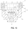
- the detector 11 includes an assembly 21 composed of a casing 18 and a cap 20, and a pressure sensor unit 15 and a passive IC tag 12 housed in a pressure holding chamber 18c inside the casing 18.
- the detector 11 is connected to the communication pipe 10 via an adapter portion 23 made of metal and having a cylindrical shape. More specifically, a cylindrical pipe end connection portion 10a located at an end portion of the communication pipe 10 and the adapter portion 23 are screwed to be connected to each other.
- the adapter portion 23 and a base portion 18a of the casing 18 are connected to each other, and watertightness therebetween is ensured by an annular sealant 18s (O-ring).
- the inside of the adapter portion 23 is an introduction chamber 23a having watertightness.
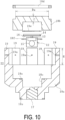
- the casing 18 includes the base portion 18a made of metal and having a cylindrical shape, a radio wave transmission portion 18b that watertightly blocks the upper end portion side of the base portion 18a, and three or more projection portions 19 made of metal and projecting above the radio wave transmission portion 18b.
- the casing 18 further includes an annular fixing portion 18d.
- the base portion 18a and the projection portions 19 are basically an integral body.
- the base portion 18a, the fixing portion 18d, and the projection portions 19 are formed of, for example, stainless steel.
- the base portion 18a includes therein a large-diameter recess in which the radio wave transmission portion 18b is disposed, and a small-diameter recess connected to a lower portion of the large-diameter recess.
- An upper end of the check valve 17 attached to a lower end portion of the base portion 18a is exposed at a bottom surface of the small-diameter recess.
- the annular sealant 18s (O-ring) is disposed inside the base portion 18a (at a bottom surface portion of the large-diameter recess) and on the lower surface of the base portion 18a. Note that the sealant 18s is appropriately disposed at a required position.
- the radio wave transmission portion 18b is formed in a disc shape and has a recess on a lower surface thereof.
- the recess on the lower surface of the radio wave transmission portion 18b and the small-diameter recess inside the base portion 18a are set to vertically face each other.
- the radio wave transmission portion 18b is mounted on the base portion 18a such that the lower surface is in contact with the bottom surface portion of the large-diameter recess inside the base portion 18a.
- the sealant 18s is interposed between the lower surface of the radio wave transmission portion 18b and the bottom surface portion of the large-diameter recess inside the base portion 18a, the upper end portion side of the base portion 18a is watertightly blocked by the radio wave transmission portion 18b.
- the pressure holding chamber 18c is formed by being surrounded by the base portion 18a and the radio wave transmission portion 18b. In other words, the pressure holding chamber 18c having watertightness is formed by the small-diameter recess inside the base portion 18a and the recess on the lower surface of the radio wave transmission portion 18b.
- the radio wave transmission portion 18b includes a circular cutout portion in a plan view at an outer edge of the top surface.
- the annular fixing portion 18d is disposed in the cutout portion.
- An outer circumferential surface of the fixing portion 18d is attachably and detachably screwed to an inner circumferential surface of an upper end opening of the base portion 18a.
- the radio wave transmission portion 18b is fixed to the base portion 18a in a state where the outer circumferential edge portion is pressed from above by the fixing portion 18d screwed with the inner circumferential surface of the upper end opening of the base portion 18a.
- the radio wave transmission portion 18b is fixed to the base portion 18a via the annular fixing portion 18d engaged with an outer edge portion of the radio wave transmission portion 18b.
- the relative dielectric constant of the radio wave transmission portion 18b is set to 5.0 or less in order to easily allow the permeation of the transmission radio wave R1 and the return radio wave R2, is set to, for example, 2.0 or more and 5.0 or less, and is more preferably set to 2.5 or more and 3.0 or less.
- the radio wave transmission portion 18b is made of, for example, polycarbonate, polyamide, or epoxy resin as the material thereof in consideration of durability, shock resistance, and the like.
- the radio wave transmission portion 18b and the base portion 18a may have any specification as long as the pressure holding chamber 18c can be formed by using the radio wave transmission portion 18b and the base portion 18a.
- the radio wave transmission portion 18b can be fixed to the base portion 18a by using another component instead of the fixing portion 18d or by using another component in addition to the fixing portion 18d.
- the projection portions 19 are disposed at intervals in the circumferential direction at positions on the outer circumferential side of the radio wave transmission portion 18b in a plan view.
- the projection portions 19 are preferably disposed at equal intervals in the circumferential direction of the radio wave transmission portion 18b. For example, three or more and eight or less projection portions 19 are disposed.
- the projection portion 19 extending straight upward is employed, but the shape is not limited to this shape. However, when upper end portions of the projection portions 19 are in contact with (joined to) each other, good radio wave communication between the IC tag 12 and the communication unit 24 cannot be ensured. Consequently, the upper end portions of the projection portions 19 are separated from each other.
- the check valve 17 is disposed between the pressure holding chamber 18c and the introduction chamber 23a.
- the check valve 17 allows only the flow of the fluid L and gas from the introduction chamber 23a side to the pressure holding chamber 18c side, and restricts (blocks) the flow from the pressure holding chamber 18c side to the introduction chamber 23a side.
- the check valve 17 interposed between the communication pipe 10 and the pressure holding chamber 18c allows only the flow from the communication pipe 10 side to the pressure holding chamber 18c side, and restricts the flow from the pressure holding chamber 18c side to the communication pipe 10 side.
- a known check valve can be used as the check valve 17.
- the IC tag 12 includes an IC chip 13 and an antenna unit 14 connected to the IC chip 13.
- the pressure sensor unit 15 is connected to the IC tag 12 (the IC chip 13).
- the IC chip 13 has a very small size, for example, a vertical dimension and a horizontal dimension of 30 mm or less (corresponding to an outer diameter of 30 mm or less) and a thickness of 5 mm or less.
- the size of the antenna unit 14 is also very small, for example, the vertical dimension and the horizontal dimension are each 50 mm or less (corresponding to an outer diameter of 50 mm or less) and the thickness is 10 mm or less.
- a ceramic antenna is used as the antenna unit 14, so the antenna is very compact.
- a plate-shaped metal ground unit 16 is arranged in contact with the lower surface of the antenna unit 14.
- the IC tag 12 and the pressure sensor unit 15 are placed in the pressure holding chamber 18c in a state where the ground unit 16 is placed on a C-shaped ring 18f attachably and detachably fitted into an annular groove formed in the recess on the lower surface of the radio wave transmission portion 18b and an annular spacer 18e is disposed on the top surface of the antenna unit 14.
- the IC tag 12 and the pressure sensor unit 15 may be placed in the pressure holding chamber 18c without using the C-shaped ring 18f.
- the spacer 18e can be optionally provided.
- the antenna unit 14 employing the ceramic antenna, the small check valve 17 that can withstand high pressure (for example, 7 to 8 MPa), and the ground unit 16 are combined, which greatly contributes to downsizing of the detector 11.
- the ground unit 16 can be in contact with the metal base portion 18a.
- the base portion 18a and the projection portions 19 can assertively function as an antenna, and thus good radio wave communication between the IC tag 12 and the communication unit 24 can be easily ensured.
- the pressure sensor unit 15 detects the pressure P in the pressure holding chamber 18c.
- the size of the pressure sensor unit 15 is about the same as that of the IC chip 13. Although the IC chip 13 and the pressure sensor unit 15 are suspended in the drawing, the IC chip 13 and the pressure sensor unit 15 can be placed flat as the antenna unit 14.
- a diameter Da is, for example, 40 mm or more and 70 mm or less.
- the top surface of the radio wave transmission portion 18b preferably has the exposed area corresponding to the diameter Da of 40 mm or more and 70 mm or less.
- a gap Db between the projection portions 19 facing each other in a plan view is set to 100% or more of the diameter Da.
- the specification, number, and positions of the projection portions 19 are based on the premise that the radio wave transmission portion 18b can be protected and good radio wave communication between the IC tag 12 and the communication unit 24 can be maintained.
- a height H and a thickness of each of the projection portions 19 be large to some extent; however, it is an essential condition for the height H that the upper end of the projection portion 19 not be projected above the flange 2a in a state where the detector 11 is placed on the surface of the marine hose 1.
- the height H of the projection portion 19 is determined to be in the range of, for example, 15 mm or more and 40 mm or less, for example, and the thickness is determined to be in the range of, for example, 3 mm or more and 8 mm or less.
- the height H of the projection portion 19 is preferably 35% or more and 45% or less of the diameter Da of the top surface of the radio wave transmission portion 18b.
- the width of the projection portion 19 is determined such that an interval W between the adjacent projection portions 19 in the circumferential direction is, for example, 10 mm or more and is more preferably 15 mm or more.
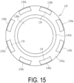
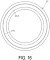
- the cap 20 is an annular body (cylindrical body) that continuously covers the upper end portions of the projection portions 19 in the circumferential direction in a plan view, and is formed of a known resin or rubber.
- the cap 20 has an inner diameter of, for example, 10 mm or more and 70 mm or less, and an outer diameter of 70 mm or more and 110 mm or less.
- the relative dielectric constant of the cap 20 is 1.0 or more and 8.0 or less.
- the resin for forming the cap 20 examples include ABS, polyvinyl chloride, polycarbonate, polyimide, and epoxy. Since it is preferable that the cap 20 has excellent weather resistance, the cap 20 is formed of a resin or rubber having excellent weather resistance, or an anti-aging agent or the like for improving weather resistance is blended with the resin or rubber to be used, or a coating material having excellent weather resistance is applied to the surface of the cap 20. For example, a coating material such as an acrylic silicone resin, a polyurethane resin, an acrylic resin, or a vinyl chloride resin is used. In order to improve durability, reinforcing fibers (short fibers) can be mixed into the resin or rubber to be used. As the reinforcing fibers, known carbon fibers, glass fibers or the like can be used.
- the cap 20 is formed with a plurality of engaging portions 20d that engage with the upper end portions of the projection portions 19. As illustrated in FIG. 5 , the cap 20 is disposed on the upper end portions of the projection portions 19 with the engaging portions 20d engaged with the upper end portions of the corresponding projection portions 19. In this embodiment, a plurality of holes that are arranged at intervals in the circumferential direction of the cap 20 and open in the bottom surface of the cap 20 are employed as the engaging portions 20d. The holes serving as the engaging portions 20d are formed in the cap 20 so as to correspond in number and arrangement to the projection portions 19.
- the cap 20 may be colored (in orange or the like) so as to be noticeable in the ocean. While the surface of the cap 20 can be coated with a coating material in a noticeable color, it is advantageous to manufacture the cap 20 from a material colored in a noticeable color in order to maintain the color for a longer period of time.
- a region on the inner circumferential side from the projection portions 19 and a region on the outer circumferential side from the projection portions 19 communicate with each other through a gap in the circumferential direction between the lower end portions of the projection portions 19 adjacent in the circumferential direction. That is, the cap 20 covers the upper end portions of the projection portions 19 but does not cover the projection portions 19 for the entire length in the height direction.
- the gap in the height direction between the lower end of the cap 20 and the lower end of each projection portion 19 (the top surface of the radio wave transmission portion 18b) is 10 mm or more, for example, 10 mm or more and 30 mm or less.
- insert holes 20a extending in the radial direction are formed at multiple locations spaced apart in the circumferential direction. Specifically, as illustrated in FIGS. 4 and 9 , an insert hole 20a is formed in the outer circumferential surface of the cap 20 so as to communicate with each engaging portion 20d.
- a screw hole 19a is formed in the outer circumferential surface of the plurality of projection portions 19. While the screw holes 19a are formed in all the projection portions 19 in this embodiment, it is only necessary that the screw holes 19a should be formed in a plurality of the projection portions 19, and it is more preferable that the screw holes 19a are formed in three or more projection portions 19. Further, the screw hole 22 may not pass through the projection portion 19 in the radial direction, but may extend halfway from the outer circumferential surface to the inner circumferential surface of the projection portion 19.
- the cap 20 When fixing the cap 20 to the casing 18, as illustrated in FIG. 11 , the cap 20 is moved from the upper side to the lower side of the projection portions 19, and the upper end portions of the projection portions 19 are inserted into the engaging portions 20d formed in the cap 20 so that the cap 20 is disposed on the upper end portions of the projection portions 19.
- the screws 22 are inserted in the radial direction from the outer circumferential side toward the inner circumferential side of the cap 20 into the insert holes 20a communicating with the engaging portions 20d in which the tip end portions of the projection portions 19 are accommodated and engaged.
- the screws 22 are screwed into the screw holes 19a disposed opposed to the respective insert holes 20a, and thus the cap 20 is firmly fixed to the casing 18.
- the screws 22 are screwed into the screw holes 19a of all the projection portions 19 in this embodiment, the screws 22 may be screwed into the screw holes 19a of every other projection 19 in the circumferential direction, for example, to fix the cap 20 to the casing 18.
- the head of the screw 22 is embedded in the insert hole 20a without protruding from the outer circumferential surface of the cap 20 to the outer circumferential side.
- the communication unit 24 is operated to transmit the transmission radio wave R1 from the radio wave transmission unit 24a toward the detector 11, and the transmission radio wave R1 is used to generate electric power in the IC tag 12.
- the IC tag 12 transmits the return radio wave R2 by the electric power, and the radio wave reception unit 24b receives the return radio wave R2.
- the detected pressure data detected by the pressure sensor unit 15 is sent via the return radio wave R2, and the detected pressure data received by the radio wave reception unit 24b is input into the calculation device 25.
- the IC tag 12 and the communication unit 24 form an RFID (Radio Frequency IDentification) system.
- the frequencies and outputs of the radio waves R1 and R2 to be communicated are appropriately set; however, since the passive IC tag 12 is used, the communication distance of the radio waves R1 and R2 between the IC tag 12 and the communication unit 24 is, for example, in the range of several tens of centimeters to several meters.
- the frequency of the radio waves (R1 and R2) used for wireless communication between the IC tag 12 and the communication unit 24 is mainly in the UHF band (depending on the country, range of 860 MHz or higher and 930 MHz or lower, range of 915 MHz or higher and 930 MHz in Japan), and the HF band (13.56 MHz) may also be used.
- the calculation device 25 stores a reference value Pc of the pressure P in the pressure holding chamber 18c for determining whether the fluid L is leaking from the flow path 1a.
- a reference value Pc of the pressure P in the pressure holding chamber 18c for determining whether the fluid L is leaking from the flow path 1a.
- an appropriate range of the reference value Pc is determined in advance by conducting experiments and simulations in consideration of the specifications and use conditions of the marine hose 1, and the reference value Pc is set within this appropriate range and stored in the calculation device 25.
- the calculation device 25 compares the pressure value of the input detected pressure data with the reference value Pc.
- the calculation device 25 determines that the fluid L is not leaking from the flow path 1a, and indicates the result by a monitor display or a sound.
- the fluid L flows into the fluid retention layer 7 from the flow path 1a, and as this happens, as illustrated in FIG. 12 , the fluid L flows through the communication pipe 10, the introduction chamber 23a, and the check valve 17, and the pressure P in the pressure holding chamber 18c increases.
- the increased pressure P is held by the check valve 17 and detected by the pressure sensor unit 15. Consequently, when the transmission radio wave R1 is transmitted from the radio wave transmission unit 24a to the detector 11 during the leakage confirmation work of the fluid L, the maximum pressure value of the pressure P up to now is received by the radio wave reception unit 24b as detected pressure data detected by the pressure sensor unit 15 and is input into the calculation device 25.
- the calculation device 25 compares the pressure value of the input detected pressure data with the reference value Pc. As a result, when the pressure value of the detected pressure data is equal to or higher than the reference value Pc, it is determined that the fluid L is leaking from the flow path 1a, and the result is notified by a monitor display or a sound.
- this detection system uses the passive IC tag 12, the work of monitoring the status of the battery life becomes unnecessary.
- the pressure in the pressure holding chamber 18c is held by using the check valve 17, and the detected pressure data detected by the pressure sensor unit 15 and received by the radio wave reception unit 24b is used as an index, and thereby whether the fluid L leaks from the flow path 1a can be more reliably determined.
- the calculation device 25 automatically determines whether the fluid L leaks from the flow path 1a.
- the operator can determine whether the fluid L leaks by comparing the preset reference value Pc with the pressure value of the detected pressure data received by the radio wave reception unit 24b.
- Other information may be stored in the IC chip 13 and transmitted via the return radio wave R2.
- information such as the specification information about the marine hose 1, the manufacturing information, and the period when the IC tag 12 is installed in the marine hose 1 or the like can be stored in the IC chip 13, and the information can be transmitted to the radio wave reception unit 24b.
- the top surface of the radio wave transmission portion 18b is protected by the aforementioned projection portions 19. Consequently, the risk of damage to the radio wave transmission portion 18b is reduced, which is advantageous for improvement of the durability of the detector 11.
- the projection portions 19 are disposed at intervals in the circumferential direction and the upper end portions of the projection portions 19 are separated from each other in a plan view, and thus the disadvantage that good radio wave communication between the IC tag 12 and the communication unit 24 is impaired by the projection portions 19 is avoidable. As a result, the ease of checking and certainty of detection of the fluid leakage can be ensured while the top surface of the radio wave transmission portion 18b is protected.
- the upper end portions of the projection portions 19 are covered by the cap 20 described above, and thus even if the upper end portions of the projection portions 19 made of metal come into contact with a certain object, it is advantageous in reducing the risk of damage to both the detector 11 and the object. For example, even if another marine hose or rope existing around the detector 11 comes into contact with the detector 11, it is possible to reduce damage to the detector 11 and the marine hose or rope. Further, since the cap 20 is firmly fixed to the casing 18, the cap 20 is not easily removed from the casing 18 even if an object comes into contact with the cap 20.
- the cap 20 is an annular body, the top surface of the radio wave transmission portion 18b is not entirely covered by the cap 20. Therefore, it is possible to prevent good radio wave communication between the IC tag 12 and the communication unit 24 from being impaired. Since a dielectric substance has an effect of causing a hole through which radio wave passes to seem large (the wavelength of the radio wave becomes shorter than that in the air), this effect occasionally contributes to slight improvement of radio wave communication by the fixation of the cap 20 to the casing 18.
- the cap 20 is firmly fixed to the casing 18 using a protruding thread portion 19b and a cap thread portion 20b.
- the cap thread portion 20b extending in the circumferential direction is formed in the cap 20.
- an annular groove that is continuous in the circumferential direction of the cap 20 and opens in the bottom surface of the cap 20 is employed as the engaging portion 20d.
- the cap thread portion 20b extending in the circumferential direction is formed in the outer circumferential surface of the annular groove serving as the engaging portion 20d.
- the protruding thread portion 19b extending in the circumferential direction is formed in the outer circumferential surfaces of the protruding portions 19.
- the cap 20 When the cap 20 is rotated in the circumferential direction at the upper end portions of the protruding portions 19 about the central axes of the cap 20 (the protruding portions 19) in a plan view, the cap thread portion 20b and the protruding thread portions 19b are screwed together. As the cap 20 is rotated, the engaging portion 20d is engaged with the upper end portion of each of the projection portions 19 to gradually move the cap 20 downward, and the cap 20 is fixed to the casing 18 in a state of being disposed on the upper end portion of each of the projection portions 19.
- the cap 20 is firmly fixed to the casing 18 using protruding fitting portions 19c and cap fitting portions 20c.
- the cap fitting portions 20c are formed in the cap 20. More specifically, a plurality of holes that are arranged at intervals in the circumferential direction of the cap 20 and open in the bottom surface of the cap 20 are employed as the engaging portions 20d.
- the cap fitting portions 20c protruding radially inward are formed in the outer circumferential surfaces of the plurality of holes serving as the engaging portions 20d.
- the protruding fitting portions 19c recessed inward in the radial direction are formed in the outer circumferential surfaces of the plurality of protruding portions 19.
- the cap fitting portions 20c recessed radially outward may be employed, and the protruding fitting portions 19c projecting radially outward can be employed. Further, instead of the plurality of holes arranged at intervals in the circumferential direction, an annular groove that is continuous in the circumferential direction of the cap 20 and opens in the bottom surface of the cap 20 can be employed as the engaging portion 20d.
- an adhesive can be used together. That is, when fixing the cap 20 to the casing 18 using each of the above-described methods, the cap 20 and the tip end portions of the projection portions 19 can be fixed to each other using a known adhesive.
- the above-described method of fixing the cap 20 to the casing 18 using the screws 22 and the above-described method of fixing the cap 20 to the casing 18 by screwing the protruding thread portions 19b and the cap thread portion 20b can be used in combination.
- the above-described method of fixing the cap 20 to the casing 18 using the screws 22 and the above-described method of fixing the cap 20 to the casing 18 by fitting the protruding fitting portions 19c and the cap fitting portions 20c may be used in combination.
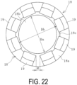
- the shape of the projection portion 19 is preferably a shape extending straight upward; however, another shape can be adopted in order to improve protective effect on the radio wave transmission portion 18b. As illustrated in FIGS. 21 and 22 , the projection portions 19 can bend at an intermediate position in the vertical direction and extend toward the center side of the radio wave transmission portion 18b in a plan view.
- each projection portion 19 is disposed on the outer circumference side of the outer circumferential edge of the top surface of the radio wave transmission portion 18b, and the height position at which the projection portion 19 is bent midway is set to a position of 8 mm or higher from the top surface of the radio wave transmission portion 18b.
- a gap Db between opposed upper ends of bent portions of the projection portions 19 is 50% or more, preferably 70% or more, and more preferably 100% or more of the diameter Da of the top surface of the radio wave transmission portion 18b.
- a gap W between upper ends of portions above the bent positions of the projection portions 19 adjacent in the circumferential direction is preferably 3 mm or more and more preferably 5 mm or more.
- the cap 20 can be fixed to the casing 18 in the same manner as the above-described various caps 20. That is, the casing 18 and the cap 20 can constitute an assembly 21 illustrated in FIGS. 23 and 24 .
- the operator can perform the work of confirming fluid leakage not only by holding the handy communication unit 24 but also by mounting the communication unit 24 on a drone 27 as illustrated in FIG. 25 .
- the detection system illustrated in FIG. 25 includes a drone 27 on which a communication unit 24 (a radio wave transmission unit 24a and a radio wave reception unit 24b) and a camera device 26 are mounted, and a calculation device 25 to which detected pressure data received by the radio wave reception unit 24b and image data acquired by the camera device 26 are input.
- the calculation device 25 is disposed, for example, on a ship or in a remote administrative office.
- the camera device 26 acquires image data of the marine hose 1 from the airspace above the marine hose 1.
- various known digital cameras and the like that acquire image data Mr of still images or moving images can be employed.
- the drone 27 is equipped with a GNSS receiver 28, and the position coordinates of the drone 27 are grasped in real time by the GNSS receiver 28.
- the operator can move the drone 27 to the airspace above and near the detector 11 (IC tag 12) based on the sequentially acquired image data Mr, and can also move the drone 27 to the airspace above and near the detector 11 (IC tag 12) by automatic control operation by inputting the position coordinates of the detector 11 to the control unit of the drone 27.
- the drone 27 When performing the work of confirming fluid leakage using this detection system, the drone 27 is flown from a measurement base located, for example, on land or on a ship, and moved into the airspace above and near the detector 11 (IC tag 12) placed on the surface of the marine hose 1. In this state, wireless communication is performed between the IC tag 12 and the communication unit 24, and the pressure data detected by the pressure sensor unit 15 and the image data Mr acquired by the camera device 26 are input to the calculation device 25.
- the presence or absence of fluid leakage is determined by the calculation device 25 based on the detected pressure data, and the presence or absence of abnormality outside the marine hose 1 is determined based on the image data Mr.
- Using the drone 27 eliminates the need for the operator to approach the marine hose 1 when performing the confirmation work, further reducing the work burden. Further, when the cap 20 is colored in a noticeable color such as orange, the position of the detector 11 can be easily confirmed using the image data Mr from the camera device 26, so that the communication unit 24 can be more easily moved to the airspace above and near the detector 11 (IC tag 12).
Landscapes
- Engineering & Computer Science (AREA)
- General Engineering & Computer Science (AREA)
- Physics & Mathematics (AREA)
- General Physics & Mathematics (AREA)
- Mechanical Engineering (AREA)
- Measuring Fluid Pressure (AREA)
- Arrangements For Transmission Of Measured Signals (AREA)
- Rigid Pipes And Flexible Pipes (AREA)
- Pipeline Systems (AREA)
Applications Claiming Priority (2)
| Application Number | Priority Date | Filing Date | Title |
|---|---|---|---|
| JP2022118905A JP2024016638A (ja) | 2022-07-26 | 2022-07-26 | マリンホースの流体漏れ検知器用のケーシングとキャップの組立体およびマリンホースの流体漏れ検知システム |
| PCT/JP2022/046535 WO2024024124A1 (fr) | 2022-07-26 | 2022-12-16 | Ensemble boîtier et capuchon pour détecteur de fuite de fluide de tuyau marin et système de détection de fuite de fluide de tuyau marin |
Publications (2)
| Publication Number | Publication Date |
|---|---|
| EP4563876A1 true EP4563876A1 (fr) | 2025-06-04 |
| EP4563876A4 EP4563876A4 (fr) | 2025-10-01 |
Family
ID=89705860
Family Applications (1)
| Application Number | Title | Priority Date | Filing Date |
|---|---|---|---|
| EP22953212.2A Pending EP4563876A4 (fr) | 2022-07-26 | 2022-12-16 | Ensemble boîtier et capuchon pour détecteur de fuite de fluide de tuyau marin et système de détection de fuite de fluide de tuyau marin |
Country Status (4)
| Country | Link |
|---|---|
| EP (1) | EP4563876A4 (fr) |
| JP (1) | JP2024016638A (fr) |
| CN (1) | CN119497799B (fr) |
| WO (1) | WO2024024124A1 (fr) |
Family Cites Families (12)
| Publication number | Priority date | Publication date | Assignee | Title |
|---|---|---|---|---|
| IL64379A (en) * | 1981-11-26 | 1989-01-31 | Plasson Maagan Michael Ind Ltd | Tube connection fittings |
| GB2117480B (en) * | 1982-03-23 | 1985-07-03 | Dunlop Ltd | Improvements in or relating to flexible hose |
| CN1098990C (zh) * | 1997-10-16 | 2003-01-15 | 樱护谟株式会社 | 管接头装置 |
| JP3947971B2 (ja) * | 2002-11-25 | 2007-07-25 | Smc株式会社 | 管継手 |
| JP4299355B2 (ja) * | 2006-12-01 | 2009-07-22 | 株式会社リプロ | 情報発信杭 |
| KR101322576B1 (ko) * | 2008-12-01 | 2013-10-28 | 니폰 필라고교 가부시키가이샤 | 수지관 이음매 |
| JP5104979B2 (ja) * | 2011-05-09 | 2012-12-19 | 横浜ゴム株式会社 | 流体搬送用ホース |
| KR102230283B1 (ko) * | 2017-02-20 | 2021-03-19 | 가부시키가이샤 후지킨 | 유체 제어기의 이상 검지 장치, 이상 검지 시스템, 이상 검지 방법 및 유체 제어기 유닛 |
| JP7049981B2 (ja) * | 2018-12-17 | 2022-04-07 | 長野計器株式会社 | 物理量測定装置 |
| JP7389313B2 (ja) * | 2018-12-18 | 2023-11-30 | 横浜ゴム株式会社 | マリンホースの流体漏れ検知システム |
| JP7225949B2 (ja) * | 2019-03-12 | 2023-02-21 | 横浜ゴム株式会社 | マリンホースの流体漏れ検知器 |
| JP7389327B2 (ja) * | 2019-09-20 | 2023-11-30 | 横浜ゴム株式会社 | マリンホースの流体漏れ検知システム |
-
2022
- 2022-07-26 JP JP2022118905A patent/JP2024016638A/ja active Pending
- 2022-12-16 WO PCT/JP2022/046535 patent/WO2024024124A1/fr not_active Ceased
- 2022-12-16 CN CN202280097947.1A patent/CN119497799B/zh active Active
- 2022-12-16 EP EP22953212.2A patent/EP4563876A4/fr active Pending
Also Published As
| Publication number | Publication date |
|---|---|
| CN119497799A (zh) | 2025-02-21 |
| JP2024016638A (ja) | 2024-02-07 |
| WO2024024124A1 (fr) | 2024-02-01 |
| EP4563876A4 (fr) | 2025-10-01 |
| CN119497799B (zh) | 2026-02-03 |
Similar Documents
| Publication | Publication Date | Title |
|---|---|---|
| JP7389327B2 (ja) | マリンホースの流体漏れ検知システム | |
| EP1879008B1 (fr) | Système souple et procédé de détection de fuites pour tuyau à double carcasse | |
| EP1795879B1 (fr) | Système et procédé de détection de fuites pour tuyaux en mer | |
| CN101105262A (zh) | 用于双胎体软管的泄漏检测系统和方法 | |
| EP2873604A2 (fr) | Flotteur de profilage à flottabilité variable | |
| JP7243270B2 (ja) | マリンホースの流体漏れ検知システム | |
| EP3706445A1 (fr) | Système de balise marine portative | |
| EP4563876A1 (fr) | Ensemble boîtier et capuchon pour détecteur de fuite de fluide de tuyau marin et système de détection de fuite de fluide de tuyau marin | |
| EP3901503B1 (fr) | Système de détection de fuite de fluide pour tuyau marin et methode associee | |
| EP4428431A1 (fr) | Système de détection de fuite de fluide de tuyau marin et son procédé de fabrication | |
| US20230008400A1 (en) | Automatic inflation management device | |
| EP4545842A1 (fr) | Système et procédé de surveillance de tuyau marin | |
| KR20160054350A (ko) | 조난신호 발생장치 | |
| JP4747834B2 (ja) | マリンホースの流体漏れ検知システム | |
| KR102801371B1 (ko) | 공기식 방현재의 관리 시스템 및 방법 | |
| KR101982574B1 (ko) | 누수 탐지 시스템 | |
| JP2024149102A (ja) | マリンホースの監視システムおよび方法 | |
| WO2023248500A1 (fr) | Système et procédé de détection de fuite de fluide pour tuyau marin | |
| KR101285139B1 (ko) | 해양 관측 부이용 기압계 모듈 어셈블리 | |
| JP2005308523A (ja) | ホースライン形状監視システム及びマリンホース | |
| BR112021010499B1 (pt) | Sistema de detecção de vazamento de fluido de mangueira marinha |
Legal Events
| Date | Code | Title | Description |
|---|---|---|---|
| STAA | Information on the status of an ep patent application or granted ep patent |
Free format text: STATUS: THE INTERNATIONAL PUBLICATION HAS BEEN MADE |
|
| PUAI | Public reference made under article 153(3) epc to a published international application that has entered the european phase |
Free format text: ORIGINAL CODE: 0009012 |
|
| STAA | Information on the status of an ep patent application or granted ep patent |
Free format text: STATUS: REQUEST FOR EXAMINATION WAS MADE |
|
| 17P | Request for examination filed |
Effective date: 20250212 |
|
| AK | Designated contracting states |
Kind code of ref document: A1 Designated state(s): AL AT BE BG CH CY CZ DE DK EE ES FI FR GB GR HR HU IE IS IT LI LT LU LV MC ME MK MT NL NO PL PT RO RS SE SI SK SM TR |
|
| A4 | Supplementary search report drawn up and despatched |
Effective date: 20250901 |
|
| RIC1 | Information provided on ipc code assigned before grant |
Ipc: F17D 5/06 20060101AFI20250826BHEP Ipc: F16L 11/12 20060101ALI20250826BHEP Ipc: F16L 11/133 20060101ALI20250826BHEP Ipc: F16L 55/00 20060101ALI20250826BHEP Ipc: G01L 19/08 20060101ALI20250826BHEP Ipc: G01M 3/28 20060101ALI20250826BHEP |
|
| DAV | Request for validation of the european patent (deleted) | ||
| DAX | Request for extension of the european patent (deleted) |