EP4564390A1 - Partie polaire de disjoncteur - Google Patents
Partie polaire de disjoncteur Download PDFInfo
- Publication number
- EP4564390A1 EP4564390A1 EP23212964.3A EP23212964A EP4564390A1 EP 4564390 A1 EP4564390 A1 EP 4564390A1 EP 23212964 A EP23212964 A EP 23212964A EP 4564390 A1 EP4564390 A1 EP 4564390A1
- Authority
- EP
- European Patent Office
- Prior art keywords
- channel
- terminal
- bushing
- conduit
- open end
- Prior art date
- Legal status (The legal status is an assumption and is not a legal conclusion. Google has not performed a legal analysis and makes no representation as to the accuracy of the status listed.)
- Pending
Links
Images



Classifications
-
- H—ELECTRICITY
- H01—ELECTRIC ELEMENTS
- H01H—ELECTRIC SWITCHES; RELAYS; SELECTORS; EMERGENCY PROTECTIVE DEVICES
- H01H33/00—High-tension or heavy-current switches with arc-extinguishing or arc-preventing means
- H01H33/60—Switches wherein the means for extinguishing or preventing the arc do not include separate means for obtaining or increasing flow of arc-extinguishing fluid
- H01H33/66—Vacuum switches
- H01H33/6606—Terminal arrangements
-
- H—ELECTRICITY
- H01—ELECTRIC ELEMENTS
- H01H—ELECTRIC SWITCHES; RELAYS; SELECTORS; EMERGENCY PROTECTIVE DEVICES
- H01H71/00—Details of the protective switches or relays covered by groups H01H73/00 - H01H83/00
- H01H71/08—Terminals; Connections
-
- H—ELECTRICITY
- H01—ELECTRIC ELEMENTS
- H01H—ELECTRIC SWITCHES; RELAYS; SELECTORS; EMERGENCY PROTECTIVE DEVICES
- H01H9/00—Details of switching devices, not covered by groups H01H1/00 - H01H7/00
- H01H9/52—Cooling of switch parts
-
- H—ELECTRICITY
- H01—ELECTRIC ELEMENTS
- H01H—ELECTRIC SWITCHES; RELAYS; SELECTORS; EMERGENCY PROTECTIVE DEVICES
- H01H33/00—High-tension or heavy-current switches with arc-extinguishing or arc-preventing means
- H01H33/60—Switches wherein the means for extinguishing or preventing the arc do not include separate means for obtaining or increasing flow of arc-extinguishing fluid
- H01H33/66—Vacuum switches
- H01H33/6606—Terminal arrangements
- H01H2033/6613—Cooling arrangements directly associated with the terminal arrangements
Definitions
- the present invention relates to a circuit breaker pole part, a bushing for a circuit breaker pole part, and a circuit breaker system.
- bushings are used to connect to terminals of a circuit breaker pole part, and due to the currents that pass through these connections temperature rises are caused due to Joule heating and at the junction where a bushing is connected to a terminal, an increased temperature can be generated due to an increased resistance associated with the connection.
- the circuit breaker pole part comprises a fixed contact and a moveable contact.
- the first terminal is electrically connected to the fixed contact or the moveable contact.
- the second terminal is electrically connected to the fixed contact or the moveable contact being the contact to which the first terminal is not electrically connected;
- air can flow through or across a surface of the first terminal to cool it.
- the at least one conduit or the at least one channel is inclined from the horizontal to any degree, air within the conduit(s)/channel(s) is heated and rises and exits the conduit(s)/channel(s) at an upper end and in doing so cold air is drawn into a lower end of the conduit(s)/channel(s) leading to a continuous flow of cold air into the conduit(s)/channel(s) that is heated and exits the conduit(s)/channel(s) and in doing so extracts heat from the first terminal to cool it.
- This is achieved via natural convection and no means such as fans are required to move the air.
- cooling of the first terminal of the circuit breaker pole part is achieved in a simple manner with no moving parts required.
- a normal circuit breaker pole part with a first terminal electrically connected to a fixed contact of the circuit breaker, for example of a vacuum interrupter, and a second terminal electrically connected to a moveable con tact of the circuit breaker has been adapted to permit the terminals to be cooled via natural convection.
- the at least one conduit or the at least one channel is at least one conduit, and the at least one conduit between the first open end and the second open end has side wall surfaces formed only by the first terminal.
- the conduit is a bounded hole through the first terminal, that could be drilled through the first terminal.
- an existing circuit breaker pole can be adapted by drilling holes through the terminal(s) to provide for air convection cooling.
- the at least one conduit or at least one channel is at least one channel in an end surface (40) of the first terminal.
- the at least one channel is an open sided channel in the end surface of the first terminal.
- the at least one boundary become at least one conduit, bounded on one side by the first terminal and bounded on the other side by the bushing, but having open ends that permits cooling air to flow through the formed conduit(s) and cool the first terminal and also cool the bushing.
- the channel in the surface of the terminal can be machined via a router for example, and an existing circuit breaker pole can be adapted for cooling.
- a width of the one or more of the at least one channel varies.
- a direction of the one or more of the at least one channel varies.
- the air flowing through the channel is made to interact with the channel side walls to an increased degree providing for increased heat extraction.
- This is achieved by the channel having a varying width and/or having bends in the channel that leads to a certain amount of turbulence of the air and the air interacts with the channel to a greater degree and exits the channel with an increased temperature difference with respect to the air entering the channel in comparison to a channel that is straight with straight and parallel side walls.
- the varying width of the channel can be made via a router for example.
- the varying direction of the channel can be made via a router for example.
- a bushing (80) is configured to connect to the first terminal, where an end surface (90) of the bushing touches the end surface of the first terminal.
- the air can enter the at least one channel via the first open end flow through the at least one channel and exit the at least one channel via the second open end.
- the open sided channel becomes a conduit with openings at each end that enables air to flow through it and cool the terminal and also cool the bushing.
- the second terminal comprises at least one conduit or at least one channel (70).
- the at least one conduit or the at least one channel of the second terminal comprises a first open end and a second open end such that air can enter the at least one conduit or the at least one channel via the first open end of the at least one conduit or the at least one channel of the second terminal, flow through the at least one conduit or the at least one channel, and exit the at least one conduit or the at least one channel via the second open end of the at least one conduit or the at least one channel of the second terminal.
- the at least one conduit or at least one channel of the second terminal is at least one conduit of the second terminal, and wherein the at least one conduit of the second terminal between the first open end and the second open end has side wall surfaces formed only by the second terminal.
- the at least one conduit or at least one channel of the second terminal is at least one channel of the second terminal in an end surface (50) of the second terminal.
- a width of the one or more of the at least one channel of the second terminal varies.
- a direction of the one or more of the at least one channel of the second terminal varies.
- a bushing (80) is configured to connect to the second terminal such that an end surface (90) of the bushing touches the end surface of the second terminal except for where the at least one channel of the second terminal is located.
- the circuit breaker pole part in use is configured to be positioned in a substantially vertical orientation.
- the at least one conduit or at least one channel in the first terminal is configured to be in a substantially vertical orientation.
- the at least one conduit or at least one channel in the second terminal is configured to be in a substantially vertical orientation.
- the circuit breaker pole part comprises a first terminal (20), and a second terminal (30).
- the circuit breaker pole part also comprises:
- the first terminal is electrically connected to the fixed contact or the moveable contact
- the second terminal is electrically connected to the fixed contact or the moveable contact being the contact to which the first terminal is not electrically connected.
- the first terminal comprises an end surface (40), and the second terminal comprises an end surface (50).
- the bushing comprises:
- the at least one conduit or the at least one channel of the bushing comprises a first open end at one end of the at least one conduit or the at least one channel and a second open end at an opposite end of the least one conduit or the at least one channel such that air can enter the at least one conduit or the at least one channel of the bushing via the first open end flow through the at least one conduit or the at least one channel of the bushing and exit the at least one conduit or the at least one channel of the bushing via the second open end.
- the end surface (90) of the bushing is configured to connect to the end surface of the first terminal of the circuit breaker pole part and/or the end surface of the second terminal of the circuit breaker pole part.
- air can flow through or across a surface of the bushing to cool it.
- the at least one conduit or the at least one channel is inclined from the horizontal to any degree
- air within the conduit(s)/channel(s) is heated and rises and exits the conduit(s)/channel(s) at an upper end and in doing so cold air is drawn into a lower end of the conduit(s) / channel(s) leading to a continuous flow of cold air into the conduit(s) / channel(s) that is heated and exits the conduit(s) / channel(s) and in doing so extracts heat from the bushing to cool it and that will also cool the first terminal.
- This is achieved via natural convection and no means such as fans are required to move the air.
- cooling of the first terminal of the circuit breaker pole part is achieved in a simple manner with no moving parts required.
- the at least one conduit or at least one channel of the bushing is at least one conduit, and the at least one conduit of the bushing between the first open end and the second open end has side wall surfaces formed only by the bushing.
- the conduit is a bounded hole through the bushing, that could be drilled through the drilled.
- an existing bushing can be adapted by drilling holes through the bushing to provide for air convection cooling.
- the at least one conduit or the at least one channel of the bushing is at least one channel in the end surface (90) of the bushing.
- the at least one channel is an open sided channel in the end surface of the bushing.
- the at least one boundary become at least one conduit, bounded on one side by the terminal and bounded on the other side by the bushing, but having open ends that permits cooling air to flow through the formed conduit(s) and cool the bushing and also cool the terminal.
- the channel in the surface of the bushing can be machined via a router for example, and a bushing can be adapted for cooling.
- a width of the one or more of the at least one channel of the bushing varies.
- a direction of the one or more of the at least one channel of the bushing varies.
- the air flowing through the channel is made to interact with the channel side walls to an increased degree providing for increased heat extraction.
- This is achieved by the channel having a varying width and/or having bends in the channel that leads to a certain amount of turbulence of the air and the air interacts with the channel to a greater degree and exits the channel with an increased temperature difference with respect to the air entering the channel in comparison to a channel that is straight with straight and parallel side walls.
- the varying width of the channel can be made via a router for example.
- the varying direction of the channel can be made via a router for example.
- the end surface of the bushing is configured to connect to the end surface of the first terminal, where the end surface (90) of the bushing touches the end surface of the first terminal, and the air can enter the at least one channel of the bushing via the first open end flow through the at least one channel of the bushing and exit the at least one channel of the bushing via the second open end.
- the end surface of the bushing is configured to connect to the end surface of the second terminal, where the end surface (90) of the bushing touches the end surface of the second terminal, and the air can enter the at least one channel of the bushing via the first open end flow through the at least one channel of the bushing and exit the at least one channel of the bushing via the second open end.
- the open sided channel becomes a conduit, due to the surface of the first terminal closing the open side of the channel, with openings at each end that enables air to flow through it and cool the terminal(s) of the circuit breaker pole part and also cool the bushing.
- the at least one channel of the bushing is configured to be in a substantially vertical orientation.
- a circuit breaker system comprising:
- the bushing is configured to connect to the circuit breaker pole part.
- the circuit breaker pole part comprises a first terminal (20); and a second terminal (30).
- the circuit breaker pole part comprises: a fixed contact; and a moveable contact.
- the first terminal is electrically connected to the fixed contact or the moveable contact, and the second terminal is electrically connected to the fixed contact or the moveable contact being the contact to which the first terminal is not electrically connected.
- the first terminal comprises: an end surface (40).
- the first terminal comprises: at least one channel (60) in the end surface of the first terminal.
- the at least one channel of the first terminal comprises a first open end at one end of the at least one channel and a second open end at an opposite the at least one channel such that air can enter the at least one channel of the first terminal via the first open end flow through the at least one channel of the first terminal and exit the at least one channel of the first terminal via the second open end.
- the bushing comprises an end surface (90).
- the bushing also comprises at least one channel (100) in the end surface of the bushing.
- the at least one channel of the bushing comprises a first open end at one end of the at least one channel and a second open end at an opposite end of the at least one channel such that air can enter the at least one channel of the bushing via the first open end flow through the at least one channel of the bushing and exit the at least one channel of the bushing via the second open end.
- the end surface of the bushing is configured to connect to the end surface of the first terminal. When the end surface of the bushing is connected to the end surface of the first terminal the air can flow through the at least one channel of the bushing, and the air can flow through the at least one channel of the first terminal.
- the first terminal and the bushing can be designed such that the channel(s) align - thus forming a number of conduits equal in number to half of the total number of channel(s) in the first terminal and bushing. This provides for a design where the conduits formed can large and where good electrical conduction between the bushing and the terminal is maintained because the amount of mating surfaces is maximised, whilst convective air cooling is provided.
- the channels need not align, where for example conduits are formed from a channel on one side and a flat surface of the mating surface on the other side,
- a number of conduits formed can be equal to the total number of channels of the bushing and the terminal. This provides for a design where cooling can be provided over a maximised surface area of the end of the bushing and over a maximised surface area of the end of the terminal, provided for an overall increased cooling effect via natural air convection.
- a width of the one or more of the at least one channel of the first terminal varies.
- a direction of the one or more of the at least one channel of the first terminal varies.
- a width of the one or more of the at least one channel of the bushing varies.
- a direction of the one or more of the at least one channel of the bushing varies.
- the at least one channel of the bushing is configured to align with the at least one channel of the first terminal.
- the system comprises a second bushing.
- the second bushing comprises an end surface (90).
- the second bushing also comprises at least one channel (100) in the end surface of the second bushing.
- the at least one channel of the second bushing comprises a first open end at one end of the at least one channel and a second open end at an opposite end of the at least one channel such that air can enter the at least one channel of the second bushing via the first open end flow through the at least one channel of the second bushing and exit the at least one channel of the second bushing via the second open end.
- the second terminal comprises an end surface (50).
- the second terminal also comprises at least one channel (70) in the end surface of the second terminal.
- the at least one channel of the second terminal comprises a first open end at one end of the at least one channel and a second open end at an opposite the at least one channel such that air can enter the at least one channel of the second terminal via the first open end flow through the at least one channel of the second terminal and exit the at least one channel of the first terminal via the second open end.
- the end surface of the second bushing is configured to connect to the end surface of the second terminal. When the end surface of the second bushing is connected to the end surface of the second terminal the air can flow through the at least one channel of the second bushing, and the air can flow through the at least one channel of the second terminal.
- the second bushing can be identical to the first bushing (the "first bushing” referred to as “bushing” above).
- the at least one channel of the second bushing is configured to align with the at least one channel of the second terminal.
- the circuit breaker pole part in use is configured to be positioned in a substantially vertical orientation.
- the at least one channel of the first terminal is configured to be in a substantially vertical orientation.
- the at least one channel of the bushing is configured to be in a substantially vertical orientation.
- the at least one channel of the second bushing is configured to be in a substantially vertical orientation.
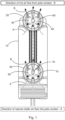
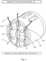
- Fig. 3 shows an isometric representation of a circuit breaker system that has a circuit breaker pole part as shown in Figs. 1-2 to which two bushings as shown in Figs. 3-4 are connected to the two terminals.
- Figs. 1-5 relates to a new circuit breaker pole part, a new bushing for a circuit breaker pole part, and a new circuit breaker system.
- end surfaces 40, 50 of terminals 20, 30 of the circuit breaker pole part are shown with channels 60, 70 in those surfaces.
- conduits, in other would bounded holes, could be provided behind those surfaces, for example having been drilled.
- An exemplar new circuit breaker pole part 10 comprises:
- the circuit breaker pole part comprises a fixed contact and a moveable contact.
- the first terminal is electrically connected to the fixed contact or the moveable contact.
- the second terminal is electrically connected to the fixed contact or the moveable contact being the contact to which the first terminal is not electrically connected.
- the first terminal comprises at least one conduit or at least one channel 60.
- the at least one conduit or the at least one channel comprises a first open end at one end of the at least one conduit or the at least one channel and a second open end at an opposite end of the least one conduit or the at least one channel such that air can enter the at least one conduit or the at least one channel via the first open end flow through the at least one conduit or the at least one channel and exit the at least one conduit or the at least one channel via the second open end.
- air can flow through or across a surface of the first terminal to cool it.
- the at least one conduit or the at least one channel is inclined from the horizontal to any degree, air within the conduit(s)/channel(s) is heated and rises and exits the conduit(s)/channel(s) at an upper end and in doing so cold air is drawn into a lower end of the conduit(s)/channel(s) leading to a continuous flow of cold air into the conduit(s)/channel(s) that is heated and exits the conduit(s)/channel(s) and in doing so extracts heat from the first terminal to cool it.
- This is achieved via natural convection and no means such as fans are required to move the air.
- cooling of the first terminal of the circuit breaker pole part is achieved in a simple manner with no moving parts required.
- a normal circuit breaker pole part with a first terminal electrically connected to a fixed contact of the circuit breaker, for example of a vacuum interrupter, and a second terminal electrically connected to a moveable con tact of the circuit breaker has been adapted to permit the terminals to be cooled via natural convection.
- the at least one conduit or the at least one channel is at least one conduit, and the at least one conduit between the first open end and the second open end has side wall surfaces formed only by the first terminal.
- the conduit is a bounded hole through the first terminal, that could be drilled through the first terminal.
- an existing circuit breaker pole can be adapted by drilling holes through the terminal(s) to provide for air convection cooling.
- the at least one conduit or at least one channel is at least one channel in an end surface 40 of the first terminal.
- the at least one channel is an open sided channel in the end surface of the first terminal.
- the at least one boundary become at least one conduit, bounded on one side by the first terminal and bounded on the other side by the bushing, but having open ends that permits cooling air to flow through the formed conduit(s) and cool the first terminal and also cool the bushing.
- the channel in the surface of the terminal can be machined via a router for example, and an existing circuit breaker pole can be adapted for cooling.
- a width of the one or more of the at least one channel varies.
- a direction of the one or more of the at least one channel varies.
- the air flowing through the channel is made to interact with the channel side walls to an increased degree providing for increased heat extraction.
- This is achieved by the channel having a varying width and/or having bends in the channel that leads to a certain amount of turbulence of the air and the air interacts with the channel to a greater degree and exits the channel with an increased temperature difference with respect to the air entering the channel in comparison to a channel that is straight with straight and parallel side walls.
- the varying width of the channel can be made via a router for example.
- the varying direction of the channel can be made via a router for example.
- a bushing 80 is configured to connect to the first terminal, where an end surface 90 of the bushing touches the end surface of the first terminal.
- the air can enter the at least one channel via the first open end flow through the at least one channel and exit the at least one channel via the second open end.
- the open sided channel becomes a conduit with openings at each end that enables air to flow through it and cool the terminal and also cool the bushing.
- the second terminal comprises at least one conduit or at least one channel 70.
- the at least one conduit or the at least one channel of the second terminal comprises a first open end and a second open end such that air can enter the at least one conduit or the at least one channel via the first open end of the at least one conduit or the at least one channel of the second terminal, flow through the at least one conduit or the at least one channel, and exit the at least one conduit or the at least one channel via the second open end of the at least one conduit or the at least one channel of the second terminal.
- the at least one conduit or at least one channel of the second terminal is at least one conduit of the second terminal, and wherein the at least one conduit of the second terminal between the first open end and the second open end has side wall surfaces formed only by the second terminal.
- the at least one conduit or at least one channel of the second terminal is at least one channel of the second terminal in an end surface 50 of the second terminal.
- a width of the one or more of the at least one channel of the second terminal varies.
- a direction of the one or more of the at least one channel of the second terminal varies.
- a bushing 80 is configured to connect to the second terminal such that an end surface 90 of the bushing touches the end surface of the second terminal except for where the at least one channel of the second terminal is located.
- the circuit breaker pole part in use is configured to be positioned in a substantially vertical orientation.
- the at least one conduit or at least one channel in the first terminal is configured to be in a substantially vertical orientation.
- the at least one conduit or at least one channel in the second terminal is configured to be in a substantially vertical orientation.
- the circuit breaker pole part comprises a first terminal (20), and a second terminal (30).
- the circuit breaker pole part also comprises: a fixed contact; and a moveable contact.
- the first terminal is electrically connected to the fixed contact or the moveable contact
- the second terminal is electrically connected to the fixed contact or the moveable contact being the contact to which the first terminal is not electrically connected.
- the first terminal comprises an end surface 40
- the second terminal comprises an end surface 50.
- the bushing comprises: at least one conduit or at least one channel 100; and an end surface 90.
- the at least one conduit or the at least one channel of the bushing comprises a first open end at one end of the at least one conduit or the at least one channel and a second open end at an opposite end of the least one conduit or the at least one channel such that air can enter the at least one conduit or the at least one channel of the bushing via the first open end flow through the at least one conduit or the at least one channel of the bushing and exit the at least one conduit or the at least one channel of the bushing via the second open end.
- the end surface (90) of the bushing is configured to connect to the end surface of the first terminal of the circuit breaker pole part and/or the end surface of the second terminal of the circuit breaker pole part.
- air can flow through or across a surface of the bushing to cool it.
- the at least one conduit or the at least one channel is inclined from the horizontal to any degree
- air within the conduit(s)/channel(s) is heated and rises and exits the conduit(s)/channel(s) at an upper end and in doing so cold air is drawn into a lower end of the conduit(s) / channel(s) leading to a continuous flow of cold air into the conduit(s) / channel(s) that is heated and exits the conduit(s) / channel(s) and in doing so extracts heat from the bushing to cool it and that will also cool the first terminal.
- This is achieved via natural convection and no means such as fans are required to move the air.
- cooling of the first terminal of the circuit breaker pole part is achieved in a simple manner with no moving parts required.
- the at least one conduit or at least one channel of the bushing is at least one conduit, and the at least one conduit of the bushing between the first open end and the second open end has side wall surfaces formed only by the bushing.
- the conduit is a bounded hole through the bushing, that could be drilled through the drilled.
- an existing bushing can be adapted by drilling holes through the bushing to provide for air convection cooling.
- the at least one conduit or the at least one channel of the bushing is at least one channel in the end surface 90 of the bushing.
- the at least one channel is an open sided channel in the end surface of the bushing.
- the at least one boundary become at least one conduit, bounded on one side by the terminal and bounded on the other side by the bushing, but having open ends that permits cooling air to flow through the formed conduit(s) and cool the bushing and also cool the terminal.
- the channel in the surface of the bushing can be machined via a router for example, and a bushing can be adapted for cooling.
- a width of the one or more of the at least one channel of the bushing varies.
- a direction of the one or more of the at least one channel of the bushing varies.
- the air flowing through the channel is made to interact with the channel side walls to an increased degree providing for increased heat extraction.
- This is achieved by the channel having a varying width and/or having bends in the channel that leads to a certain amount of turbulence of the air and the air interacts with the channel to a greater degree and exits the channel with an increased temperature difference with respect to the air entering the channel in comparison to a channel that is straight with straight and parallel side walls.
- the varying width of the channel can be made via a router for example.
- the varying direction of the channel can be made via a router for example.
- the end surface of the bushing is configured to connect to the end surface of the first terminal, where the end surface 90 of the bushing touches the end surface of the first terminal, and the air can enter the at least one channel of the bushing via the first open end flow through the at least one channel of the bushing and exit the at least one channel of the bushing via the second open end.
- the end surface of the bushing is configured to connect to the end surface of the second terminal, where the end surface 90 of the bushing touches the end surface of the second terminal, and the air can enter the at least one channel of the bushing via the first open end flow through the at least one channel of the bushing and exit the at least one channel of the bushing via the second open end.
- the open sided channel becomes a conduit, due to the surface of the first terminal closing the open side of the channel, with openings at each end that enables air to flow through it and cool the terminal(s) of the circuit breaker pole part and also cool the bushing.
- the at least one channel of the bushing is configured to be in a substantially vertical orientation.
- An exemplar new circuit breaker system comprises:
- the bushing is configured to connect to the circuit breaker pole part.
- the circuit breaker pole part comprises a first terminal 20; and a second terminal (30).
- the circuit breaker pole part comprises: a fixed contact; and a moveable contact.
- the first terminal is electrically connected to the fixed contact or the moveable contact, and the second terminal is electrically connected to the fixed contact or the moveable contact being the contact to which the first terminal is not electrically connected.
- the first terminal comprises: an end surface 40.
- the first terminal comprises: at least one channel 60 in the end surface of the first terminal.
- the at least one channel of the first terminal comprises a first open end at one end of the at least one channel and a second open end at an opposite the at least one channel such that air can enter the at least one channel of the first terminal via the first open end flow through the at least one channel of the first terminal and exit the at least one channel of the first terminal via the second open end.
- the bushing comprises an end surface 90.
- the bushing also comprises at least one channel 100 in the end surface of the bushing.
- the at least one channel of the bushing comprises a first open end at one end of the at least one channel and a second open end at an opposite end of the at least one channel such that air can enter the at least one channel of the bushing via the first open end flow through the at least one channel of the bushing and exit the at least one channel of the bushing via the second open end.
- the end surface of the bushing is configured to connect to the end surface of the first terminal. When the end surface of the bushing is connected to the end surface of the first terminal the air can flow through the at least one channel of the bushing, and the air can flow through the at least one channel of the first terminal.
- the first terminal and the bushing can be designed such that the channel(s) align - thus forming a number of conduits equal in number to half of the total number of channel(s) in the first terminal and bushing. This provides for a design where the conduits formed can large and where good electrical conduction between the bushing and the terminal is maintained because the amount of mating surfaces is maximised, whilst convective air cooling is provided.
- the channels need not align, where for example conduits are formed from a channel on one side and a flat surface of the mating surface on the other side,
- a number of conduits formed can be equal to the total number of channels of the bushing and the terminal. This provides for a design where cooling can be provided over a maximised surface area of the end of the bushing and over a maximised surface area of the end of the terminal, provided for an overall increased cooling effect via natural air convection.
- a width of the one or more of the at least one channel of the first terminal varies.
- a direction of the one or more of the at least one channel of the first terminal varies.
- a width of the one or more of the at least one channel of the bushing varies.
- a direction of the one or more of the at least one channel of the bushing varies.
- the at least one channel of the bushing is configured to align with the at least one channel of the first terminal.
- the system comprises a second bushing.
- the second bushing comprises an end surface 90.
- the second bushing also comprises at least one channel 100 in the end surface of the second bushing.
- the at least one channel of the second bushing comprises a first open end at one end of the at least one channel and a second open end at an opposite end of the at least one channel such that air can enter the at least one channel of the second bushing via the first open end flow through the at least one channel of the second bushing and exit the at least one channel of the second bushing via the second open end.
- the second terminal comprises an end surface 50.
- the second terminal also comprises at least one channel 70 in the end surface of the second terminal.
- the at least one channel of the second terminal comprises a first open end at one end of the at least one channel and a second open end at an opposite the at least one channel such that air can enter the at least one channel of the second terminal via the first open end flow through the at least one channel of the second terminal and exit the at least one channel of the first terminal via the second open end.
- the end surface of the second bushing is configured to connect to the end surface of the second terminal. When the end surface of the second bushing is connected to the end surface of the second terminal the air can flow through the at least one channel of the second bushing, and the air can flow through the at least one channel of the second terminal.
- the second bushing can be identical to the first bushing (the "first bushing” referred to as “bushing” above).
- the at least one channel of the second bushing is configured to align with the at least one channel of the second terminal.
- the circuit breaker pole part in use is configured to be positioned in a substantially vertical orientation.
- the at least one channel of the first terminal is configured to be in a substantially vertical orientation.
- the at least one channel of the second terminal is configured to be in a substantially vertical orientation.
- the at least one channel of the bushing is configured to be in a substantially vertical orientation.
- the at least one channel of the second bushing is configured to be in a substantially vertical orientation.
- the inventors realized that in effect existing circuit breaker pole parts and existing bushings that connect to terminals of the circuit breaker pole parts could be modified to provide cooling at or near the connection points between the bushing and the terminals to which they connect. This is achieved by providing open sided channels in the end surfaces of the terminals of the pole part and/or of the bushings to enable air to convect through the holes to provide cooling at the interface. Alternatively or additionally holes can be drilled through the terminals and/or the bushing, near to where the connection is to be made, again enabling air to flow through the holes via convection to provide cooling.
- the new design of the terminal/bushing provides a volume of fresh air flowing through the connection region naturally by convection, considerably helping the removal of heat generated by the passage of high currents.
- the new terminal /bushing design allows to increase the heat dissipation surfaces all around the system, maintaining and guaranteeing the contact between the two surfaces through which the current passes.
- the special channels (grooves) geometry and the vertical orientation (introduced on both surfaces) facilitates the effectiveness of natural ventilation, this allows more heat to be removed in the same unit of time, increasing the heat removal efficiency.
- the switching element and its terminals are a part of the main circuit which must be cooled due to ohmic losses at nominal current.
- the cooling makes it necessary to conduct the heat losses to the ambient air.
- circuit breaker overall dimensions will remain unchanged, from dielectric point of view, it has no impact, and cooling is provided enabling the required standards to be met and increase current loads to be utilized, because improved cooling is provided.
Landscapes
- Breakers (AREA)
- Driving Mechanisms And Operating Circuits Of Arc-Extinguishing High-Tension Switches (AREA)
Priority Applications (2)
| Application Number | Priority Date | Filing Date | Title |
|---|---|---|---|
| EP23212964.3A EP4564390A1 (fr) | 2023-11-29 | 2023-11-29 | Partie polaire de disjoncteur |
| CN202411737615.2A CN120072583A (zh) | 2023-11-29 | 2024-11-29 | 断路器极部件 |
Applications Claiming Priority (1)
| Application Number | Priority Date | Filing Date | Title |
|---|---|---|---|
| EP23212964.3A EP4564390A1 (fr) | 2023-11-29 | 2023-11-29 | Partie polaire de disjoncteur |
Publications (1)
| Publication Number | Publication Date |
|---|---|
| EP4564390A1 true EP4564390A1 (fr) | 2025-06-04 |
Family
ID=89030076
Family Applications (1)
| Application Number | Title | Priority Date | Filing Date |
|---|---|---|---|
| EP23212964.3A Pending EP4564390A1 (fr) | 2023-11-29 | 2023-11-29 | Partie polaire de disjoncteur |
Country Status (2)
| Country | Link |
|---|---|
| EP (1) | EP4564390A1 (fr) |
| CN (1) | CN120072583A (fr) |
Citations (4)
| Publication number | Priority date | Publication date | Assignee | Title |
|---|---|---|---|---|
| US20100282713A1 (en) * | 2007-12-07 | 2010-11-11 | Abb Technology Ltd. | Heat dissipating means for circuit-breaker and circuit-breaker with such a heat dissipating means |
| US20160233042A1 (en) * | 2015-02-06 | 2016-08-11 | Abb Technology Ag | Circuit breaker contact arm |
| EP3171381A1 (fr) * | 2015-11-20 | 2017-05-24 | Siemens Aktiengesellschaft | Structure de contact d'un disjoncteur |
| WO2018122630A1 (fr) * | 2016-12-29 | 2018-07-05 | Abb Schweiz Ag | Bloc de contact d'appareillage de connexion |
-
2023
- 2023-11-29 EP EP23212964.3A patent/EP4564390A1/fr active Pending
-
2024
- 2024-11-29 CN CN202411737615.2A patent/CN120072583A/zh active Pending
Patent Citations (4)
| Publication number | Priority date | Publication date | Assignee | Title |
|---|---|---|---|---|
| US20100282713A1 (en) * | 2007-12-07 | 2010-11-11 | Abb Technology Ltd. | Heat dissipating means for circuit-breaker and circuit-breaker with such a heat dissipating means |
| US20160233042A1 (en) * | 2015-02-06 | 2016-08-11 | Abb Technology Ag | Circuit breaker contact arm |
| EP3171381A1 (fr) * | 2015-11-20 | 2017-05-24 | Siemens Aktiengesellschaft | Structure de contact d'un disjoncteur |
| WO2018122630A1 (fr) * | 2016-12-29 | 2018-07-05 | Abb Schweiz Ag | Bloc de contact d'appareillage de connexion |
Also Published As
| Publication number | Publication date |
|---|---|
| CN120072583A (zh) | 2025-05-30 |
Similar Documents
| Publication | Publication Date | Title |
|---|---|---|
| US7641506B2 (en) | Electrical connection device and connector | |
| US8278582B2 (en) | Heat dissipating means for circuit-breaker and circuit-breaker with such a heat dissipating means | |
| US5753875A (en) | Heat sink for contact stems of a vacuum interrupter and a vacuum interrupter therewith | |
| EP2828873B1 (fr) | Appareil de refroidissement pour appareillage de commutation avec refroidissement de joint de barres omnibus amélioré | |
| CN113412523A (zh) | 功率半导体的冷却 | |
| KR101608685B1 (ko) | 효율적인 열 방산을 위한 통풍 채널을 포함하는 회로 차단기 | |
| EP4564390A1 (fr) | Partie polaire de disjoncteur | |
| US12355201B2 (en) | Cooled inlet cold plate design for robust electrical isolation | |
| EP1758136B1 (fr) | Appareil de commutation électrique et dissipateur thermique associé | |
| CN114446721B (zh) | 一种低温升的万能式断路器 | |
| EP2306482B1 (fr) | Assemblage de terminal de circuit principal pour disjoncteur à vide | |
| CN102017039A (zh) | 断路器及其散热装置 | |
| CN110767482B (zh) | 一种气体绝缘金属封闭开关 | |
| CN216818194U (zh) | 一种断路器结构 | |
| CN113725017B (zh) | 一种固封极柱隔离触头座组件及开关柜 | |
| EP4715857A1 (fr) | Disjoncteur | |
| EP4715858A1 (fr) | Disjoncteur | |
| EP4560674A1 (fr) | Appareillage de commutation | |
| CN113193506B (zh) | 用于中压空气或气体绝缘开关设备的隔室 | |
| CN220874108U (zh) | 配电盒盒体结构及高压配电盒 | |
| CN114203479B (zh) | 一种断路器结构 | |
| KR20120024500A (ko) | 전류-운반 세그먼트, 그 냉각 방법, 및 전기 장치 | |
| CN116110749A (zh) | 一种断路器散热结构 | |
| JPWO2012066792A1 (ja) | ブッシング | |
| CN118507295A (zh) | 一种用于断路器的散热装置 |
Legal Events
| Date | Code | Title | Description |
|---|---|---|---|
| PUAI | Public reference made under article 153(3) epc to a published international application that has entered the european phase |
Free format text: ORIGINAL CODE: 0009012 |
|
| STAA | Information on the status of an ep patent application or granted ep patent |
Free format text: STATUS: THE APPLICATION HAS BEEN PUBLISHED |
|
| AK | Designated contracting states |
Kind code of ref document: A1 Designated state(s): AL AT BE BG CH CY CZ DE DK EE ES FI FR GB GR HR HU IE IS IT LI LT LU LV MC ME MK MT NL NO PL PT RO RS SE SI SK SM TR |
|
| STAA | Information on the status of an ep patent application or granted ep patent |
Free format text: STATUS: REQUEST FOR EXAMINATION WAS MADE |
|
| 17P | Request for examination filed |
Effective date: 20251113 |