EP4564509A1 - Festkörperelektrolyt, herstellungsverfahren dafür, sekundärbatterie, batteriemodul, batteriepack und elektrische vorrichtung - Google Patents
Festkörperelektrolyt, herstellungsverfahren dafür, sekundärbatterie, batteriemodul, batteriepack und elektrische vorrichtung Download PDFInfo
- Publication number
- EP4564509A1 EP4564509A1 EP23917189.5A EP23917189A EP4564509A1 EP 4564509 A1 EP4564509 A1 EP 4564509A1 EP 23917189 A EP23917189 A EP 23917189A EP 4564509 A1 EP4564509 A1 EP 4564509A1
- Authority
- EP
- European Patent Office
- Prior art keywords
- solid electrolyte
- layer
- porous layer
- battery
- secondary battery
- Prior art date
- Legal status (The legal status is an assumption and is not a legal conclusion. Google has not performed a legal analysis and makes no representation as to the accuracy of the status listed.)
- Pending
Links
Images

Classifications
-
- H—ELECTRICITY
- H01—ELECTRIC ELEMENTS
- H01M—PROCESSES OR MEANS, e.g. BATTERIES, FOR THE DIRECT CONVERSION OF CHEMICAL ENERGY INTO ELECTRICAL ENERGY
- H01M10/00—Secondary cells; Manufacture thereof
- H01M10/05—Accumulators with non-aqueous electrolyte
- H01M10/056—Accumulators with non-aqueous electrolyte characterised by the materials used as electrolytes, e.g. mixed inorganic/organic electrolytes
- H01M10/0561—Accumulators with non-aqueous electrolyte characterised by the materials used as electrolytes, e.g. mixed inorganic/organic electrolytes the electrolyte being constituted of inorganic materials only
- H01M10/0562—Solid materials
-
- H—ELECTRICITY
- H01—ELECTRIC ELEMENTS
- H01M—PROCESSES OR MEANS, e.g. BATTERIES, FOR THE DIRECT CONVERSION OF CHEMICAL ENERGY INTO ELECTRICAL ENERGY
- H01M10/00—Secondary cells; Manufacture thereof
- H01M10/05—Accumulators with non-aqueous electrolyte
- H01M10/052—Li-accumulators
- H01M10/0525—Rocking-chair batteries, i.e. batteries with lithium insertion or intercalation in both electrodes; Lithium-ion batteries
-
- H—ELECTRICITY
- H01—ELECTRIC ELEMENTS
- H01M—PROCESSES OR MEANS, e.g. BATTERIES, FOR THE DIRECT CONVERSION OF CHEMICAL ENERGY INTO ELECTRICAL ENERGY
- H01M10/00—Secondary cells; Manufacture thereof
- H01M10/05—Accumulators with non-aqueous electrolyte
- H01M10/058—Construction or manufacture
-
- H—ELECTRICITY
- H01—ELECTRIC ELEMENTS
- H01M—PROCESSES OR MEANS, e.g. BATTERIES, FOR THE DIRECT CONVERSION OF CHEMICAL ENERGY INTO ELECTRICAL ENERGY
- H01M4/00—Electrodes
- H01M4/02—Electrodes composed of, or comprising, active material
- H01M4/04—Processes of manufacture in general
- H01M4/0402—Methods of deposition of the material
- H01M4/0407—Methods of deposition of the material by coating on an electrolyte layer
-
- H—ELECTRICITY
- H01—ELECTRIC ELEMENTS
- H01M—PROCESSES OR MEANS, e.g. BATTERIES, FOR THE DIRECT CONVERSION OF CHEMICAL ENERGY INTO ELECTRICAL ENERGY
- H01M4/00—Electrodes
- H01M4/02—Electrodes composed of, or comprising, active material
- H01M4/36—Selection of substances as active materials, active masses, active liquids
- H01M4/362—Composites
- H01M4/366—Composites as layered products
-
- H—ELECTRICITY
- H01—ELECTRIC ELEMENTS
- H01M—PROCESSES OR MEANS, e.g. BATTERIES, FOR THE DIRECT CONVERSION OF CHEMICAL ENERGY INTO ELECTRICAL ENERGY
- H01M4/00—Electrodes
- H01M4/02—Electrodes composed of, or comprising, active material
- H01M4/36—Selection of substances as active materials, active masses, active liquids
- H01M4/38—Selection of substances as active materials, active masses, active liquids of elements or alloys
- H01M4/40—Alloys based on alkali metals
-
- H—ELECTRICITY
- H01—ELECTRIC ELEMENTS
- H01M—PROCESSES OR MEANS, e.g. BATTERIES, FOR THE DIRECT CONVERSION OF CHEMICAL ENERGY INTO ELECTRICAL ENERGY
- H01M4/00—Electrodes
- H01M4/02—Electrodes composed of, or comprising, active material
- H01M4/36—Selection of substances as active materials, active masses, active liquids
- H01M4/48—Selection of substances as active materials, active masses, active liquids of inorganic oxides or hydroxides
- H01M4/485—Selection of substances as active materials, active masses, active liquids of inorganic oxides or hydroxides of mixed oxides or hydroxides for inserting or intercalating light metals, e.g. LiTi2O4 or LiTi2OxFy
-
- H—ELECTRICITY
- H01—ELECTRIC ELEMENTS
- H01M—PROCESSES OR MEANS, e.g. BATTERIES, FOR THE DIRECT CONVERSION OF CHEMICAL ENERGY INTO ELECTRICAL ENERGY
- H01M4/00—Electrodes
- H01M4/02—Electrodes composed of, or comprising, active material
- H01M4/36—Selection of substances as active materials, active masses, active liquids
- H01M4/48—Selection of substances as active materials, active masses, active liquids of inorganic oxides or hydroxides
- H01M4/50—Selection of substances as active materials, active masses, active liquids of inorganic oxides or hydroxides of manganese
- H01M4/505—Selection of substances as active materials, active masses, active liquids of inorganic oxides or hydroxides of manganese of mixed oxides or hydroxides containing manganese for inserting or intercalating light metals, e.g. LiMn2O4 or LiMn2OxFy
-
- H—ELECTRICITY
- H01—ELECTRIC ELEMENTS
- H01M—PROCESSES OR MEANS, e.g. BATTERIES, FOR THE DIRECT CONVERSION OF CHEMICAL ENERGY INTO ELECTRICAL ENERGY
- H01M4/00—Electrodes
- H01M4/02—Electrodes composed of, or comprising, active material
- H01M4/36—Selection of substances as active materials, active masses, active liquids
- H01M4/48—Selection of substances as active materials, active masses, active liquids of inorganic oxides or hydroxides
- H01M4/52—Selection of substances as active materials, active masses, active liquids of inorganic oxides or hydroxides of nickel, cobalt or iron
- H01M4/525—Selection of substances as active materials, active masses, active liquids of inorganic oxides or hydroxides of nickel, cobalt or iron of mixed oxides or hydroxides containing iron, cobalt or nickel for inserting or intercalating light metals, e.g. LiNiO2, LiCoO2 or LiCoOxFy
-
- H—ELECTRICITY
- H01—ELECTRIC ELEMENTS
- H01M—PROCESSES OR MEANS, e.g. BATTERIES, FOR THE DIRECT CONVERSION OF CHEMICAL ENERGY INTO ELECTRICAL ENERGY
- H01M4/00—Electrodes
- H01M4/02—Electrodes composed of, or comprising, active material
- H01M4/36—Selection of substances as active materials, active masses, active liquids
- H01M4/58—Selection of substances as active materials, active masses, active liquids of inorganic compounds other than oxides or hydroxides, e.g. sulfides, selenides, tellurides, halogenides or LiCoFy; of polyanionic structures, e.g. phosphates, silicates or borates
-
- H—ELECTRICITY
- H01—ELECTRIC ELEMENTS
- H01M—PROCESSES OR MEANS, e.g. BATTERIES, FOR THE DIRECT CONVERSION OF CHEMICAL ENERGY INTO ELECTRICAL ENERGY
- H01M4/00—Electrodes
- H01M4/02—Electrodes composed of, or comprising, active material
- H01M4/36—Selection of substances as active materials, active masses, active liquids
- H01M4/58—Selection of substances as active materials, active masses, active liquids of inorganic compounds other than oxides or hydroxides, e.g. sulfides, selenides, tellurides, halogenides or LiCoFy; of polyanionic structures, e.g. phosphates, silicates or borates
- H01M4/5825—Oxygenated metallic salts or polyanionic structures, e.g. borates, phosphates, silicates, olivines
-
- H—ELECTRICITY
- H01—ELECTRIC ELEMENTS
- H01M—PROCESSES OR MEANS, e.g. BATTERIES, FOR THE DIRECT CONVERSION OF CHEMICAL ENERGY INTO ELECTRICAL ENERGY
- H01M4/00—Electrodes
- H01M4/02—Electrodes composed of, or comprising, active material
- H01M4/36—Selection of substances as active materials, active masses, active liquids
- H01M4/58—Selection of substances as active materials, active masses, active liquids of inorganic compounds other than oxides or hydroxides, e.g. sulfides, selenides, tellurides, halogenides or LiCoFy; of polyanionic structures, e.g. phosphates, silicates or borates
- H01M4/583—Carbonaceous material, e.g. graphite-intercalation compounds or CFx
-
- H—ELECTRICITY
- H01—ELECTRIC ELEMENTS
- H01M—PROCESSES OR MEANS, e.g. BATTERIES, FOR THE DIRECT CONVERSION OF CHEMICAL ENERGY INTO ELECTRICAL ENERGY
- H01M4/00—Electrodes
- H01M4/02—Electrodes composed of, or comprising, active material
- H01M4/36—Selection of substances as active materials, active masses, active liquids
- H01M4/58—Selection of substances as active materials, active masses, active liquids of inorganic compounds other than oxides or hydroxides, e.g. sulfides, selenides, tellurides, halogenides or LiCoFy; of polyanionic structures, e.g. phosphates, silicates or borates
- H01M4/583—Carbonaceous material, e.g. graphite-intercalation compounds or CFx
- H01M4/587—Carbonaceous material, e.g. graphite-intercalation compounds or CFx for inserting or intercalating light metals
-
- H—ELECTRICITY
- H01—ELECTRIC ELEMENTS
- H01M—PROCESSES OR MEANS, e.g. BATTERIES, FOR THE DIRECT CONVERSION OF CHEMICAL ENERGY INTO ELECTRICAL ENERGY
- H01M4/00—Electrodes
- H01M4/02—Electrodes composed of, or comprising, active material
- H01M4/64—Carriers or collectors
- H01M4/66—Selection of materials
- H01M4/665—Composites
- H01M4/667—Composites in the form of layers, e.g. coatings
-
- H—ELECTRICITY
- H01—ELECTRIC ELEMENTS
- H01M—PROCESSES OR MEANS, e.g. BATTERIES, FOR THE DIRECT CONVERSION OF CHEMICAL ENERGY INTO ELECTRICAL ENERGY
- H01M50/00—Constructional details or processes of manufacture of the non-active parts of electrochemical cells other than fuel cells, e.g. hybrid cells
- H01M50/10—Primary casings; Jackets or wrappings
- H01M50/102—Primary casings; Jackets or wrappings characterised by their shape or physical structure
- H01M50/103—Primary casings; Jackets or wrappings characterised by their shape or physical structure prismatic or rectangular
-
- H—ELECTRICITY
- H01—ELECTRIC ELEMENTS
- H01M—PROCESSES OR MEANS, e.g. BATTERIES, FOR THE DIRECT CONVERSION OF CHEMICAL ENERGY INTO ELECTRICAL ENERGY
- H01M50/00—Constructional details or processes of manufacture of the non-active parts of electrochemical cells other than fuel cells, e.g. hybrid cells
- H01M50/20—Mountings; Secondary casings or frames; Racks, modules or packs; Suspension devices; Shock absorbers; Transport or carrying devices; Holders
- H01M50/204—Racks, modules or packs for multiple batteries or multiple cells
-
- H—ELECTRICITY
- H01—ELECTRIC ELEMENTS
- H01M—PROCESSES OR MEANS, e.g. BATTERIES, FOR THE DIRECT CONVERSION OF CHEMICAL ENERGY INTO ELECTRICAL ENERGY
- H01M10/00—Secondary cells; Manufacture thereof
- H01M10/05—Accumulators with non-aqueous electrolyte
- H01M10/054—Accumulators with insertion or intercalation of metals other than lithium, e.g. with magnesium or aluminium
-
- H—ELECTRICITY
- H01—ELECTRIC ELEMENTS
- H01M—PROCESSES OR MEANS, e.g. BATTERIES, FOR THE DIRECT CONVERSION OF CHEMICAL ENERGY INTO ELECTRICAL ENERGY
- H01M4/00—Electrodes
- H01M4/02—Electrodes composed of, or comprising, active material
- H01M2004/021—Physical characteristics, e.g. porosity, surface area
-
- H—ELECTRICITY
- H01—ELECTRIC ELEMENTS
- H01M—PROCESSES OR MEANS, e.g. BATTERIES, FOR THE DIRECT CONVERSION OF CHEMICAL ENERGY INTO ELECTRICAL ENERGY
- H01M4/00—Electrodes
- H01M4/02—Electrodes composed of, or comprising, active material
- H01M2004/026—Electrodes composed of, or comprising, active material characterised by the polarity
- H01M2004/027—Negative electrodes
-
- H—ELECTRICITY
- H01—ELECTRIC ELEMENTS
- H01M—PROCESSES OR MEANS, e.g. BATTERIES, FOR THE DIRECT CONVERSION OF CHEMICAL ENERGY INTO ELECTRICAL ENERGY
- H01M4/00—Electrodes
- H01M4/02—Electrodes composed of, or comprising, active material
- H01M2004/026—Electrodes composed of, or comprising, active material characterised by the polarity
- H01M2004/028—Positive electrodes
-
- H—ELECTRICITY
- H01—ELECTRIC ELEMENTS
- H01M—PROCESSES OR MEANS, e.g. BATTERIES, FOR THE DIRECT CONVERSION OF CHEMICAL ENERGY INTO ELECTRICAL ENERGY
- H01M2300/00—Electrolytes
- H01M2300/0017—Non-aqueous electrolytes
- H01M2300/0065—Solid electrolytes
- H01M2300/0068—Solid electrolytes inorganic
-
- H—ELECTRICITY
- H01—ELECTRIC ELEMENTS
- H01M—PROCESSES OR MEANS, e.g. BATTERIES, FOR THE DIRECT CONVERSION OF CHEMICAL ENERGY INTO ELECTRICAL ENERGY
- H01M2300/00—Electrolytes
- H01M2300/0017—Non-aqueous electrolytes
- H01M2300/0065—Solid electrolytes
- H01M2300/0068—Solid electrolytes inorganic
- H01M2300/0071—Oxides
-
- H—ELECTRICITY
- H01—ELECTRIC ELEMENTS
- H01M—PROCESSES OR MEANS, e.g. BATTERIES, FOR THE DIRECT CONVERSION OF CHEMICAL ENERGY INTO ELECTRICAL ENERGY
- H01M2300/00—Electrolytes
- H01M2300/0017—Non-aqueous electrolytes
- H01M2300/0065—Solid electrolytes
- H01M2300/0068—Solid electrolytes inorganic
- H01M2300/008—Halides
-
- H—ELECTRICITY
- H01—ELECTRIC ELEMENTS
- H01M—PROCESSES OR MEANS, e.g. BATTERIES, FOR THE DIRECT CONVERSION OF CHEMICAL ENERGY INTO ELECTRICAL ENERGY
- H01M2300/00—Electrolytes
- H01M2300/0088—Composites
- H01M2300/0094—Composites in the form of layered products, e.g. coatings
-
- Y—GENERAL TAGGING OF NEW TECHNOLOGICAL DEVELOPMENTS; GENERAL TAGGING OF CROSS-SECTIONAL TECHNOLOGIES SPANNING OVER SEVERAL SECTIONS OF THE IPC; TECHNICAL SUBJECTS COVERED BY FORMER USPC CROSS-REFERENCE ART COLLECTIONS [XRACs] AND DIGESTS
- Y02—TECHNOLOGIES OR APPLICATIONS FOR MITIGATION OR ADAPTATION AGAINST CLIMATE CHANGE
- Y02E—REDUCTION OF GREENHOUSE GAS [GHG] EMISSIONS, RELATED TO ENERGY GENERATION, TRANSMISSION OR DISTRIBUTION
- Y02E60/00—Enabling technologies; Technologies with a potential or indirect contribution to GHG emissions mitigation
- Y02E60/10—Energy storage using batteries
Definitions
- This application relates to the field of secondary battery technologies, and in particular, to a solid electrolyte, a preparation method thereof, a secondary battery, a battery module, a battery pack, and an electric apparatus.
- secondary batteries have been widely used in energy storage power supply systems such as hydroelectric, thermal, wind, and solar power plants, and many other fields including electric tools, electric bicycles, electric motorcycles, electric vehicles, military equipment, and aerospace. With the popularization of secondary batteries, higher requirements are imposed on the performance and safety of secondary batteries.
- the solid electrolyte includes a compact layer and a porous layer located on at least one side of the compact layer.
- the porous layer helps to improve wettability of an interface between the solid electrolyte and a positive electrode plate/negative electrode plate or a current collector on a positive electrode side/current collector on a negative electrode side, and also facilitates direct introduction of a positive electrode active material/negative electrode active material into pores, thereby reducing interface resistance of a battery, and improving rate performance and low-temperature performance of the battery.
- this application provides a solid electrolyte for a secondary battery.
- the solid electrolyte includes a compact layer and a porous layer located on at least one side of the compact layer, where a porosity of the porous layer is greater than a porosity of the compact layer.
- the solid electrolyte includes the compact layer and the porous layer located on at least one side of the compact layer, and the porosity of the porous layer is greater than the porosity of the compact layer. This helps to improve the wettability of the interface between the solid electrolyte and the positive electrode plate/negative electrode plate or the current collector on the positive electrode side/current collector on the negative electrode side, thereby reducing the interface resistance of the battery, and improving the rate performance and room-temperature/low-temperature cycling stability of the battery.
- the porous layer is disposed on at least one side of the compact layer, and the porosity of the porous layer is greater than the porosity of the compact layer.
- the porous layer with a larger porosity helps to reduce the interface resistance between the solid electrolyte and the positive electrode plate/negative electrode plate and improve the room-temperature/low-temperature cycling stability of the battery.
- the porous layer is disposed on a surface of the compact layer.
- the porous layer disposed on the surface of the compact layer can not only effectively reduce the interface resistance of the battery but also helps to improve the rate performance and roomtemperature/low-temperature cycling stability of the battery.
- two porous layers are provided and are respectively connected to two opposite surfaces of the compact layer.
- the two opposite surfaces of the compact layer being each provided with one porous layer helps to simultaneously improve the interface kinetics between the solid electrolyte and the positive and negative electrode plates, reduce the interface resistance of the battery, and improve the rate performance and roomtemperature/low-temperature cycling stability of the battery.
- a thickness ratio of any one of the porous layers to the compact layer is 0.5 to 7.5, optionally 1 to 4.
- Controlling the thickness ratio of any one of the porous layers to the compact layer to be 0.5 to 7.5 can control an electrochemical-mechanical effect and does not cause cycling performance degradation of the battery caused by stress deformation of the solid electrolyte due to a mechanical stress during cycling. This helps to reduce the interface resistance of the battery, improve the rate performance and roomtemperature/low-temperature cycling stability of the battery, and balances the mechanical properties and electrical properties of the solid electrolyte. Further controlling the thickness ratio of the porous layer to the compact layer to be 1 to 4 can ensure that the solid electrolyte has a larger specific surface area while having a low body phase internal resistance, helping to further reduce the internal resistance of the battery, increase the specific surface area of the porous layer, and optimize the kinetic performance of the battery.
- an ionic conductivity of the porous layer is not less than 1/10 of an ionic conductivity of the compact layer.
- Controlling the ionic conductivity of the porous layer to be not less than 1/10 of the ionic conductivity of the compact layer improves the interface kinetics between the solid electrolyte and the positive electrode plate/negative electrode plate, ensures the ionic conductivity of the solid electrolyte, and balances the interface kinetics and the ionic conductivity of the solid electrolyte.
- a contact angle of molten sodium on the surface of the porous layer of the solid electrolyte is ⁇ 90°, optionally ⁇ 70°.
- the contact angle of molten sodium on the surface of the porous layer of the solid electrolyte being ⁇ 90° indicates that the porous layer of the solid electrolyte has better wettability to molten sodium.
- the collocation of the porous layer and the positive/negative electrode active material can improve the interface kinetics between the solid electrolyte and the positive electrode plate/negative electrode plate, reduce the interface resistance of the battery, and improve the rate performance and room-temperature/low-temperature cycling stability of the battery.
- the contact angle of molten sodium on the surface of the porous layer of the solid electrolyte being ⁇ 70° can further reduce the interface resistance of the battery and improve the rate performance and room-temperature/low-temperature cycling stability of the battery.
- the compact layer and the porous layer both include an inorganic solid electrolyte material, where the inorganic solid electrolyte material includes one or more of a sulfur-based electrolyte, a sodium superionic conductor, and an oxide electrolyte.
- the sulfur-based electrolyte includes one or more of Na 2 S-P 2 S 5 , Na 11 Sn 2 PnX 12 , and Na 3 Pn y Pn' 1-y X z X' 4-z , where Pn includes at least one of P and Sb, X includes at least one of S and Se, Pn' includes at least one of Si, Sn, and Ge, X' includes at least one of F, Br, and Cl, 0 ⁇ y ⁇ 1, and 0 ⁇ z ⁇ 4.
- the sodium superionic conductor includes Na 3+x M y M' 2-y Si 2-z P z O 12 , where M and M' each independently include at least one of Zr, Ca, Mg, Zn, La, Ti, and Nb, 0 ⁇ x ⁇ 1, 0 ⁇ y ⁇ 2, and 0 ⁇ z ⁇ 2.
- the oxide electrolyte includes at least one of Na- ⁇ -Al 2 O 3 and Na- ⁇ "-Al 2 O 3 , where Na- ⁇ -Al 2 O 3 includes ⁇ -Na 2 O ⁇ 11Al 2 O 3 , and Na- ⁇ "-Al 2 O 3 includes ⁇ "-Na 2 O ⁇ 5Al 2 O 3 , and optionally, the oxide electrolyte further includes an inorganic oxide, where the inorganic oxide includes one or more of Li 2 O, MgO, TiO 2 , ZrO 2 , Y 2 O 3 , MnO 2 , SiO 2 , and Fe 2 O 3 , and a mass percentage of the inorganic oxide is 0.5% to 30% based on a total mass of the oxide electrolyte.
- the sulfur-based electrolyte, the sodium superionic conductor, and the oxide electrolyte all help to reduce the interface resistance of the battery and improve the rate performance and room-temperature/low-temperature cycling stability of the battery.
- this application provides a preparation method of a solid electrolyte for a secondary battery, including the following steps:
- the above preparation method is simple and easy to operate, and the prepared solid electrolyte helps to improve the wettability of the interface between the solid electrolyte and the positive electrode plate/negative electrode plate, thereby reducing the interface resistance of the battery and improving the rate performance and room-temperature/low-temperature cycling stability of the battery.
- the pore forming agent includes one or more of activated carbon, carbon black, ethyl cellulose, starch, ammonium carbonate, ammonium bicarbonate, polyethylene glycol, polymethacrylic acid, and polymethyl methacrylate.
- the above pore forming agent is likely to decompose at high temperatures, forming pores inside the porous layer and increasing the porosity of the porous layer, so that the porosity of the porous layer is greater than the porosity of the compact layer, and the specific surface area of the porous layer is increased.
- the remaining carbon element can improve the interface kinetics between the solid electrolyte and the positive electrode plate/negative electrode plate, reduce the interface resistance of the battery, and improve the rate performance and room-temperature/low-temperature cycling stability of the battery.
- a mass percentage of the pore forming agent is 5% to 50% based on a total mass of the porous layer precursor.
- Controlling the mass percentage of the pore forming agent within a suitable range can balance the ionic conductivity of the porous layer and the interface kinetics of the solid electrolyte, reduce the interface resistance of the battery, and improve the rate performance and room-temperature/low-temperature cycling stability of the battery.
- a mass percentage of the compact layer is 30% to 70% based on a total mass of the solid electrolyte precursor, optionally 50% to 70%.
- Controlling the mass percentage of the compact layer to be 30% to 70% based on the total mass of the solid electrolyte precursor can ensure the ionic conductivity of the solid electrolyte as well as reduce the interface resistance of the battery and improve the rate performance and room-temperature/low-temperature cycling stability of the battery. Further controlling the mass percentage of the compact layer to be 50% to 70% based on the total mass of the solid electrolyte precursor helps to further reduce the interface resistance of the battery and improve the rate performance and room-temperature/low-temperature cycling stability of the battery.
- conditions for the calcining include: the calcining is first maintained at a temperature of 400°C to 600°C for 0.5 h to 4 h and then maintained at a temperature of 800°C to 1300°C for 0.5 h to 24 h.
- Suitable calcining temperature and time facilitate full release of the pore forming agent, thereby increasing the porosity of the porous layer, increasing the specific surface area and ionic conductivity of the porous layer, improving the wettability of the interface between the solid electrolyte and the positive electrode plate/negative electrode plate, reducing the interface resistance of the battery, and improving the rate performance and room-temperature/low-temperature cycling stability of the battery.
- the first compaction and the second compaction are performed at a pressure of 10 MPa to 50 MPa, and the third compaction is performed at a pressure of 50 MPa to 300 MPa.
- Controlling the pressures for the first compaction, second compaction and third compaction to be within suitable ranges facilitates shaping of the solid electrolyte and avoids or reduces delamination between the porous layer and the compact layer during preparation of the solid electrolyte.
- a particle size of the inorganic solid electrolyte powder is 1 ⁇ m to 10 ⁇ m.
- Controlling the particle size of the inorganic solid electrolyte powder to be 1 ⁇ m to 10 ⁇ m facilitates uniform mixing of the inorganic solid electrolyte powder and the pore forming agent to realize uniform distribution of the pores of the porous layer, reduces the interface resistance of the battery, and improves the rate performance and room-temperature/low-temperature cycling stability of the battery. In addition, this also helps to reduce a compaction pressure increase caused by an excessively large particle size, thereby reducing device wear and tear.
- this application provides a secondary battery including a positive electrode plate, a negative electrode plate, and the solid electrolyte according to the first aspect or a solid electrolyte prepared using the preparation method of a solid electrolyte according to the second aspect.
- the secondary battery includes a positive electrode active material, where the positive electrode active material is located in pores of the porous layer of the solid electrolyte on a positive electrode plate side.
- the positive electrode active material is distributed in the pores of the porous layer of the solid electrolyte on the positive electrode plate side. This can avoid or reduce the use of a binder, increase a proportion of the positive electrode active material, and improve the kinetic performance of the positive electrode plate.
- the porous layer has a large specific surface area, and the positive electrode active material distributed in the pores of the porous layer helps to increase a contact area between the positive electrode active material and the solid electrolyte, reduce the interface resistance of the battery, and improve the rate performance and room-temperature/low-temperature cycling stability of the battery.
- the positive electrode active material is synthesized in situ in the porous layer of the solid electrolyte, where methods for the in-situ synthesis include at least one of a hydrothermal method, an electrodeposition method, a sol-gel method, an electrospinning method, a chemical vapor deposition method, a physical vapor deposition method, and an impregnation method, and the physical vapor deposition method includes at least one of vacuum evaporation, magnetron sputtering, ion sputtering, molecular beam epitaxy, and atomic layer deposition.
- All the above in-situ synthesis methods can realize distribution of the positive electrode active material in the pores of the porous layer of the solid electrolyte, and reduce the interface resistance between the positive electrode active material and the solid electrolyte.
- the positive electrode active material includes at least one of a layered transition metal oxide, a polyanionic compound, and a Prussian blue compound, and optionally includes one or more of NaNi 1/3 Fe 1/3 Mn 1/3 O 2 , Na(Cu 1/9 Ni 2/9 Fe 1/3 Mn 1/3 )O 2 , Na 2/3 Ni 1/6 Mn 2/3 Cu 1/9 Mg 1/18 O 2 , Na 4 Fe 3 (PO 4 ) 2 P 2 O 7 , NaFePO 4 , Na 3 V 2 (PO 4 ) 3 , Na 1.9 CoFe(CN) 6 , Na 2 NiFe(CN) 6 , and NaMnFe(CN) 6 .
- All the above positive electrode active materials help to reduce the interface resistance of the battery and improve the rate performance and room-temperature/low-temperature cycling stability of the battery.
- a coating layer is provided on a surface of the positive electrode active material, where the coating layer includes one or more of carbon material, ZrO 2 , TiO 2 , polyaniline, polypyrrole, poly(3,4-ethylenedioxythiophene), aluminum oxide, zinc oxide, titanium oxide, zirconium oxide, magnesium oxide, silicon oxide, lanthanum oxide, sodium fluoride, lithium fluoride, and aluminum fluoride, where the carbon material includes one or more of amorphous carbon, graphite, and graphene.
- the positive electrode active material including the coating layer helps to improve the high-voltage cycling stability and room-temperature/low-temperature cycling stability of the battery.
- a thickness of the coating layer is 2 nm to 1000 nm, optionally 10 nm to 100 nm.
- Controlling the thickness of the coating layer to be within a suitable range helps to improve the high-voltage cycling stability and electrical properties of the battery.
- the secondary battery includes a negative electrode active material, where the negative electrode active material is located in the pores of the porous layer of the solid electrolyte on a negative electrode plate side.
- the negative electrode active material is distributed in the pores of the porous layer of the solid electrolyte on the negative electrode plate side. This can increase a proportion of the negative electrode active material, increase a charge/discharge capacity of the battery, and improve the interface kinetics between the solid electrolyte and the negative electrode plate.
- the porous layer has a large specific surface area, and the negative electrode active material distributed in the pores of the porous layer helps to increase a contact area between the negative electrode active material and the solid electrolyte, reduce the interface resistance of the battery, and improve the rate performance and room-temperature/low-temperature cycling stability of the battery.
- the negative electrode active material fills the pores of the porous layer of the solid electrolyte through thermal infusion.
- the thermal infusion significantly improves an interface kinetic process.
- the negative electrode active material includes sodium metal or sodium alloy.
- the sodium alloy includes any one of sodium-potassium alloy, sodium-potassium-lithium alloy, sodium-magnesium alloy, and sodium-zinc alloy.
- the secondary battery is a sodium secondary battery with no negative electrode.
- the solid electrolyte includes a conductive material, where the conductive material is located in the pores of the porous layer of the solid electrolyte on the positive electrode plate side and/or negative electrode plate side, and the conductive material is one or more selected from carbon nanotubes, graphite, graphene, and Super P.
- the conductive material being located in the pores of the porous layer of the solid electrolyte on the negative electrode plate side helps to increase the electronic conductivity.
- the negative electrode plate includes a negative electrode current collector and a primer layer disposed on at least one surface of the negative electrode current collector, where the primer layer includes one or more of carbon nanotubes, graphite, graphene, silver and carbon composite nanoparticles, and tin and carbon composite nanoparticles.
- the primer layer not only has excellent conductibility but also facilitates uniform deposition of metal ions on the surface of the current collector, thereby improving the cycling performance and safety of the battery.
- an areal density of the primer layer is 5 g/m 2 to 50 g/m 2 .
- the primer layer with an areal density of 5 g/m 2 to 50 g/m 2 facilitates uniform distribution of nucleation sites and promotes uniform deposition of metal, without affecting transport of electrons.
- a thickness of the primer layer is 2 ⁇ m to 100 ⁇ m.
- Controlling the thickness of the primer layer to be 2 ⁇ m to 100 ⁇ m can provide sufficient nucleation sites, facilitates uniform deposition of metal ions, and inhibits dendrites.
- this application provides a battery module including the secondary battery according to the third aspect of this application.
- this application provides a battery pack including the secondary battery according to the third aspect of this application or the battery module according to the fourth aspect of this application.
- this application provides an electric apparatus including at least one of the secondary battery according to the third aspect of this application, the battery module according to the fourth aspect of this application, and the battery pack according to the fifth aspect of this application.
- Ranges disclosed in this application are defined in the form of lower and upper limits.
- a given range is defined by one lower limit and one upper limit selected, where the selected lower and upper limits define boundaries of that special range. Ranges defined in this way may or may not include end values, and any combination may be used, meaning that any lower limit may be combined with any upper limit to form a range. For example, if ranges of 60-120 and 80-110 are provided for a specific parameter, it is understood that ranges of 60-110 and 80-120 can also be envisioned.
- low limit values of a range are given as 1 and 2
- upper limit values of the range are given as 3, 4, and 5, the following ranges can all be envisioned: 1-3, 1-4, 1-5, 2-3, 2-4, and 2-5.
- a value range of "a-b” is a short representation of any combination of real numbers between a and b, where both a and b are real numbers.
- a value range of "0-5" means that all real numbers in the range of "0-5" are listed herein and "0-5" is just a short representation of combinations of these values.
- a parameter expressed as an integer greater than or equal to 2 is equivalent to disclosure that the parameter is, for example, an integer of 2, 3, 4, 5, 6, 7, 8, 9, 10, 11, or 12.
- steps in this application can be performed sequentially or randomly, preferably, performed sequentially.
- the method including steps (a) and (b) indicates that the method may include steps (a) and (b) performed sequentially or may include steps (b) and (a) performed sequentially.
- the foregoing method may further include step (c), which indicates that step (c) may be added to the method in any ordinal position, for example, the method may include steps (a), (b), and (c), steps (a), (c), and (b), steps (c), (a), and (b), or the like.
- the term "or” is inclusive.
- the phrase “A or B” means “A, B, or both A and B”. More specifically, any one of the following conditions satisfies the condition "A or B”: A is true (or present) and B is false (or not present); A is false (or not present) and B is true (or present); or both A and B are true (or present).
- inorganic solid electrolytes have become a hot research topic due to their excellent chemical stability and wide electrochemical stability window.
- this application provides a solid electrolyte for a secondary battery.
- the solid electrolyte includes a compact layer and a porous layer located on at least one side of the compact layer, where a porosity of the porous layer is greater than a porosity of the compact layer.
- the porous layer is located on at least one side of the compact layer.
- the porous layer is located on one side of the compact layer or on both sides of the compact layer.
- the compact layer and the porous layer may be in surface contact, or there may be any other intermediate layer in between.
- the solid electrolyte includes a compact layer and one porous layer, where the porous layer is located on a side of the compact layer facing the positive electrode plate.
- the solid electrolyte includes a compact layer and one porous layer, where the porous layer is located on a side of the compact layer facing the negative electrode plate.
- the solid electrolyte includes a compact layer and two porous layers, where the compact layer is located between the two porous layers.
- the solid electrolyte includes the compact layer and the porous layer located on at least one side of the compact layer, and the porosity of the porous layer is greater than the porosity of the compact layer. This helps to improve the wettability of the interface between the solid electrolyte and the positive electrode plate/negative electrode plate, thereby reducing the interface resistance of the battery and improving the rate performance and room-temperature/low-temperature cycling stability of the battery.
- the porous layer is disposed on at least one side of the compact layer, and the porosity of the porous layer is greater than the porosity of the compact layer.
- the porous layer with a larger porosity helps to reduce the interface resistance between the solid electrolyte and the positive electrode plate/negative electrode plate and improve the room-temperature/low-temperature cycling stability of the battery.
- the porous layer is disposed on the surface of the compact layer.
- the porous layer being formed on the surface of the compact layer can effectively reduce the interface resistance of the battery and also helps to improve the rate performance and room-temperature/low-temperature cycling stability of the battery.
- two porous layers are provided and are respectively connected to two opposite surfaces of the compact layer.
- the two opposite surfaces of the compact layer are each provided with one porous layer, where one porous layer is in contact with the positive electrode plate, and the other porous layer is in contact with the negative electrode plate. This helps to simultaneously improve the interface kinetics between the solid electrolyte and the positive and negative electrode plates, reduce the interface resistance of the battery, and improve the rate performance and room-temperature/low-temperature cycling stability of the battery.
- the two porous layers respectively connected to the two opposite surfaces of the compact layer have the same thickness, that is, the solid electrolyte is a symmetrical structure.
- the two porous layers respectively connected to the two opposite surfaces of the compact layer have the different thicknesses, that is, the solid electrolyte is an asymmetrical structure.
- a thickness ratio of any one of the porous layers to the compact layer is 0.5 to 7.5, optionally 1 to 4.
- the thickness ratio of any one of the porous layers to the compact layer is optionally 0.5, 1, 1.5, 2, 2.5, 3, 3.5, 4, 4.5, 5, 5.5, 6.5, 7, or 7.5.
- Controlling the thickness ratio of any one of the porous layers to the compact layer to be 0.5 to 7.5 can control an electrochemical-mechanical effect and does not cause cycling performance degradation of the battery caused by stress deformation of the solid electrolyte due to a mechanical stress during cycling. This helps to reduce the interface resistance of the battery, improve the rate performance and roomtemperature/low-temperature cycling stability of the battery, and balances the mechanical properties and electrical properties of the solid electrolyte. Further controlling the thickness ratio of the porous layer to the compact layer to be 1 to 4 can achieve a larger specific surface area while ensuring the ionic conductivity of the solid electrolyte, helping to further reduce the internal resistance of the battery, increase the specific surface area of the porous layer, and optimize the kinetic performance of the battery.
- a thickness of the compact layer is 0.2 mm to 0.6 mm, and a thickness of any porous layer is 0.3 mm to 1.5 mm.
- the thickness of the compact layer is randomly 0.2 mm, 0.3 mm, 0.4 mm, 0.5 mm, or 0.6 mm.
- the thickness of the porous layer is randomly 0.3 mm, 0.4 mm, 0.5 mm, 0.6 mm, 0.7 mm, 0.8 mm, 0.9 mm, 1.0 mm, 1.1 mm, 1.2 mm, 1.3 mm, 1.4 mm, or 1.5 mm.
- the compact layer and porous layer within these ranges can further improve the performance of the battery and avoid excessively high internal resistance of the battery.
- the ionic conductivity of the porous layer is not less than 1/10 of the ionic conductivity of the compact layer.
- a ratio of the ionic conductivity of the porous layer to the ionic conductivity of the compact layer is optionally 1/9, 1/8, 1/7, 1/6, 1/5, 1/4, 1/3, 1/2, or 2/3.
- Controlling the ionic conductivity of the porous layer to be not less than 1/10 of the ionic conductivity of the compact layer improves the interface kinetics between the solid electrolyte and the positive electrode plate/negative electrode plate, ensures the ionic conductivity of the solid electrolyte, and balances the interface kinetics and the ionic conductivity of the solid electrolyte.
- the ionic conductivity of the porous layer is 5 ⁇ 10 -4 S ⁇ cm -1 to 2 ⁇ 10 -3 S ⁇ cm -1 . In some embodiments, the ionic conductivity of the porous layer is optionally 5 ⁇ 10 -4 S ⁇ cm -1 , 6 ⁇ 10 -4 S ⁇ cm -1 , 7 ⁇ 10 -4 S ⁇ cm -1 , 8 ⁇ 10 -4 S ⁇ cm -1 , 9 ⁇ 10 -4 S ⁇ cm -1 , 1 ⁇ 10 -3 S ⁇ cm -1 , 1.2 ⁇ 10 -3 S ⁇ cm -1 , 1.4 ⁇ 10 -3 S ⁇ cm -1 , 1.5 ⁇ 10 -3 S ⁇ cm -1 , 1.6 ⁇ 10 -3 S ⁇ cm -1 , 1.8 ⁇ 10 -3 S ⁇ cm -1 , or 2 ⁇ 10 -3 S ⁇ cm -1 .
- the ionic conductivity of the compact layer is 1 ⁇ 10 -3 S ⁇ cm -1 to 1 ⁇ 10 -2 S - em -1 .
- the ionic conductivity of the porous layer is optionally 1 ⁇ 10 -3 S ⁇ cm -1 , 1.5 ⁇ 10 -3 S ⁇ cm -1 , 2 ⁇ 10 -3 S ⁇ cm -1 , 2.5 ⁇ 10 -3 S ⁇ cm -1 , 3 ⁇ 10 -3 S ⁇ cm -1 , 3.5 ⁇ 10 -3 S ⁇ cm -1 , 4 ⁇ 10 -3 S ⁇ cm -1 , 4.5 ⁇ 10 -3 S ⁇ cm -1 , 5 ⁇ 10 -3 S ⁇ cm -1 , 5.5 ⁇ 10 -3 S ⁇ cm -1 , 6 ⁇ 10 -3 S ⁇ cm -1 , 6.5 ⁇ 10 -3 S ⁇ cm -1 , 7 ⁇ 10 -3 S ⁇ cm -1 , 7.5 ⁇ 10 -3 S ⁇ cm -1 , 8 ⁇ 10 -3 S
- Controlling the ionic conductivity of the compact layer and the ionic conductivity of the porous layer within suitable ranges allows the solid electrolyte to have excellent ion transport capability and improves the electrical properties of the battery.
- a contact angle of molten sodium on the surface of the porous layer of the solid electrolyte is ⁇ 90°, optionally ⁇ 70°. In some embodiments, the contact angle of molten sodium on the surface of the porous layer of the solid electrolyte is optionally 90°, 85°, 80°, 75°, 70°, 60°, 50°, 40°, 30°, 20°, 10°, or 5°.
- the contact angle of molten sodium on the surface of the porous layer of the solid electrolyte can be tested using known methods in the art, for example, by dropwise adding molten sodium onto a surface of a porous layer/compact layer/porous layer solid electrolyte or a porous layer/compact layer solid electrolyte, then taking an image of the surface of the electrolyte with a high-resolution camera (Grasshopper GRAS-50S5M-C) equipped with a Fujinon HF75SA-1 lens, and measuring the contact angle using ImageJ software. Test processes of comparative examples and other examples were the same as above.
- the contact angle of molten sodium on the surface of the porous layer of the solid electrolyte being ⁇ 90° indicates that the porous layer of the solid electrolyte has better wettability to molten sodium.
- the collocation of the porous layer and the negative electrode active material can improve the interface kinetics between the solid electrolyte and the positive electrode plate/negative electrode plate, reduce the interface resistance of the battery, and improve the rate performance and room-temperature/low-temperature cycling stability of the battery.
- the contact angle of molten sodium on the surface of the porous layer of the solid electrolyte being ⁇ 70° can further reduce the interface resistance of the battery and improve the rate performance and room-temperature/low-temperature cycling stability of the battery.
- the compact layer and the porous layer both include an inorganic solid electrolyte material, where the inorganic solid electrolyte material includes one or more of a sulfur-based electrolyte, a sodium superionic conductor, and an oxide electrolyte.
- the sulfur-based electrolyte includes one or more of Na 2 S-P 2 S 5 , Na 11 Sn 2 PnX 12 , and Na 3 Pn y Pn' 1-y X z X' 4-z , where Pn includes at least one of P and Sb, X includes at least one of S and Se, Pn' includes at least one of Si, Sn, and Ge, X' includes at least one of F, Br, and Cl, 0 ⁇ y ⁇ 1, and 0 ⁇ z ⁇ 4.
- y is optionally 0.1, 0.2, 0.3, 0.4, 0.5, 0.6, 0.7, 0.8, 0.9, or 1.
- z is optionally 0.1, 0.2, 0.3, 0.4, 0.5, 0.6, 0.7, 0.8, 0.9, 1, 1.2, 1.4, 1.5, 1.6, 1.8, 2, 2.2, 2.4, 2.5, 2.6, 2.8, 3, 3.2, 3.4, 3.5, 3.6, 3.8, or 4.
- the sulfur-based electrolyte includes Na 11 Sn 2 PS 12 , Na 11 Sn 2 PS 12 , Na 10 SnP 2 S 12 , Na 10 GeP 2 S 12 , and Na 2.9375 PS 3.9375 Cl 0.0625 .
- the sodium superionic conductor includes Na 3+x M y M' 2-y Si 2-z P z O 12 , where M and M' each independently include at least one of Zr, Ca, Mg, Zn, La, Ti, and Nb, 0 ⁇ x ⁇ 1, 0 ⁇ y ⁇ 2, and 0 ⁇ z ⁇ 2.
- x is optionally 0, 0.1, 0.2, 0.3, 0.4, 0.5, 0.6, 0.7, 0.8, 0.9, or 1.
- y is optionally 0.1, 0.2, 0.3, 0.4, 0.5, 0.6, 0.7, 0.8, 0.9, 1, 1.1, 1.2, 1.3, 1.4, 1.5, 1.6, 1.7, 1.8, or 1.9.
- z is optionally0, 0.1, 0.2, 0.3, 0.4, 0.5, 0.6, 0.7, 0.8, 0.9, 1, 1.1, 1.2, 1.3, 1.4, 1.5, 1.6, 1.7, 1.8, or 1.9.
- the sodium superionic conductor solid electrolyte includes at least one of Na 3.4 Zr 1.9 Zn 0.1 Si 2.2 P 0.8 O 12 , Na 3 Zr 1.75 Mg 0.25 Si 2 PO 12 , Na 3.3 Zr 1.7 La 0.3 Si 2 PO 12 , and Na 3.1 Ca 0.05 Zr 1.95 Si 2 PO 12 .
- the oxide electrolyte includes at least one of Na- ⁇ -Al 2 O 3 and Na- ⁇ "-Al 2 O 3 , where Na- ⁇ -Al 2 O 3 includes ⁇ -Na 2 O ⁇ 11Al 2 O 3 , and Na- ⁇ "-Al 2 O 3 includes ⁇ "-Na 2 O ⁇ 5Al 2 O 3 .
- the oxide electrolyte further includes an inorganic oxide, where the inorganic oxide includes one or more of Li 2 O, MgO, TiO 2 , ZrO 2 , Y 2 O 3 , MnO 2 , SiO 2 , and Fe 2 O 3 , and a mass percentage of the inorganic oxide is 0.5% to 30% based on a total mass of the oxide electrolyte.
- a mass percentage of the inorganic oxide is optionally 0.5%, 1%, 5%, 7%, 10%, 12%, 15%, 18%, 20%, 23%, 25%, 28%, or 30% based on the total mass of the oxide electrolyte.
- the sulfur-based electrolyte, the sodium superionic conductor, and the oxide electrolyte all help to reduce the interface resistance of the battery and improve the rate performance and room-temperature/low-temperature cycling stability of the battery.
- This application further provides a preparation method of a solid electrolyte for a secondary battery, including the following steps:
- the first compaction and the second compaction are performed in a random order.
- the porous layer precursor is prepared first; then the inorganic solid electrolyte powder is laid on the porous layer precursor for the second compaction to form a compact layer on a surface of the porous layer precursor; and then the third compaction is directly performed.
- the compact layer is prepared first; then inorganic solid electrolyte powder and the pore forming agent are laid on the compact layer to form a porous layer precursor on a surface of the compact layer; and then the third compaction is directly performed.
- the above preparation method is simple and easy to operate, and the prepared solid electrolyte helps to improve the wettability of the interface between the solid electrolyte and the positive electrode plate/negative electrode plate, thereby reducing the interface resistance of the battery and improving the rate performance and room-temperature/low-temperature cycling stability of the battery.
- the pore forming agent includes one or more of activated carbon, carbon black, ethyl cellulose, starch, ammonium carbonate, ammonium bicarbonate, polyethylene glycol, polymethacrylic acid, and polymethyl methacrylate.
- the above pore forming agent is likely to decompose at high temperatures, forming pores inside the porous layer and increasing the porosity of the porous layer, so that the porosity of the porous layer is greater than the porosity of the compact layer, and the specific surface area of the porous layer is increased.
- the remaining carbon element can improve the interface kinetics between the solid electrolyte and the positive electrode plate/negative electrode plate, reduce the interface resistance of the battery, and improve the rate performance and room-temperature/low-temperature cycling stability of the battery.
- a mass percentage of the pore forming agent is 5% to 50% based on a total mass of the porous layer precursor.
- the mass percentage of the pore forming agent is optionally 5%, 6%, 8%, 10%, 15%, 20%, 25%, 30%, 35%, 40%, 42%, 44%, 45%, 46%, 48%, or 50% based on the total mass of the porous layer precursor.
- Controlling the mass percentage of the pore forming agent within a suitable range can balance the ionic conductivity of the porous layer and the interface kinetics of the solid electrolyte, reduce the interface resistance of the battery, and improve the rate performance and room-temperature/low-temperature cycling stability of the battery.
- a mass percentage of the compact layer is 30% to 70% based on a total mass of the solid electrolyte precursor, optionally 50% to 70%.
- the mass percentage of the compact layer is optionally 30%, 32%, 34%, 35%, 36%, 38%, 40%, 45%, 50%, 55%, 60%, 62%, 64%, 65%, 66%, 68%, or 70% based on the total mass of the solid electrolyte precursor.
- Controlling the mass percentage of the compact layer to be 30% to 70% based on the total mass of the solid electrolyte precursor can ensure the ionic conductivity of the solid electrolyte as well as reduce the interface resistance of the battery and improve the rate performance and room-temperature/low-temperature cycling stability of the battery. Further controlling the mass percentage of the compact layer to be 50% to 70% based on the total mass of the solid electrolyte precursor helps to further reduce the interface resistance of the battery and improve the rate performance and room-temperature/low-temperature cycling stability of the battery.
- conditions for the calcining include: the calcining is first maintained at a temperature of 400°C to 600°C for 0.5 h to 4 h and then maintained at a temperature of 800°C to 1300°C for 0.5 h to 24 h.
- the conditions for the calcining include: the calcining is first maintained at a temperature of 400°C for 4 h and then maintained at a temperature of 1300°C for 0.5 h.
- the conditions for the calcining include: the calcining is first maintained at a temperature of 500°C for 3 h and then maintained at a temperature of 1000°C for 20 h.
- the conditions for the calcining include: the calcining is first maintained at a temperature of 600°C for 0.5 h and then maintained at a temperature of 800°C for 15 h.
- the conditions for the calcining include: the calcining is first maintained at a temperature of 500°C for 3 h and then maintained at a temperature of 800°C for 24 h.
- Suitable calcining temperature and time facilitate full combustion of the pore forming agent, thereby increasing the porosity of the porous layer, increasing the specific surface area and ionic conductivity of the porous layer, improving the wettability of the interface between the solid electrolyte and the positive electrode plate/negative electrode plate, reducing the interface resistance of the battery, and improving the rate performance and room-temperature/low-temperature cycling stability of the battery.
- the first compaction and the second compaction are performed at a pressure of 10 MPa to 50 MPa, and the third compaction is performed at a pressure of 50 MPa to 300 MPa.
- the first compaction and the second compaction are optionally performed at a pressure of 10 MPa, 15 MPa, 20 MPa, 25 MPa, 30 MPa, 35 MPa, 40 MPa, 45 MPa, or 50 MPa
- the third compaction is optionally performed at a pressure of 50 MPa, 60 MPa, 80 MPa, 100 MPa, 150 MPa, 220 MPa, 230 MPa, 250 MPa, 260 MPa, 280 MPa, or 300 MPa.
- Controlling the pressures for the first compaction, second compaction and third compaction to be within suitable ranges facilitates shaping of the solid electrolyte and avoids or reduces delamination between the porous layer and the compact layer during preparation of the solid electrolyte.
- a particle size of the inorganic solid electrolyte powder is 1 ⁇ m to 10 ⁇ m. In some embodiments, the particle size of the inorganic solid electrolyte powder is optionally 1 ⁇ m, 2 ⁇ m, 3 ⁇ m, 4 ⁇ m, 5 ⁇ m, 6 ⁇ m, 7 ⁇ m, 8 ⁇ m, 9 ⁇ m, or 10 ⁇ m.
- Controlling the particle size of the inorganic solid electrolyte powder to be 1 ⁇ m to 10 ⁇ m facilitates uniform mixing of the inorganic solid electrolyte powder and the pore forming agent to realize uniform distribution of the pores of the porous layer, reduces the interface resistance of the battery, and improves the rate performance and room-temperature/low-temperature cycling stability of the battery. In addition, this also helps to reduce a compaction pressure increase caused by an excessively large particle size, thereby reducing device wear and tear.
- a secondary battery includes a positive electrode plate, a negative electrode plate, and the solid electrolyte according to some embodiments or a solid electrolyte prepared using the preparation method according to some embodiments.
- the secondary battery includes a positive electrode active material, where the positive electrode active material is located in pores of a porous layer of the solid electrolyte on a positive electrode plate side.
- the positive electrode active material being located in the pores of the porous layer of the solid electrolyte on the positive electrode plate side means that the positive electrode active material is located in the pores of the porous layer on a side of the solid electrolyte facing the positive electrode plate.
- the positive electrode active material is distributed in the pores of the porous layer of the solid electrolyte on the positive electrode plate side. This can avoid or reduce the use of a binder, increase a proportion of the positive electrode active material, and improve the kinetic performance of the positive electrode plate.
- the porous layer has a large specific surface area, and the positive electrode active material distributed in the pores of the porous layer helps to increase a contact area between the positive electrode active material and the solid electrolyte, reduce the interface resistance of the battery, and improve the rate performance and room-temperature/low-temperature cycling stability of the battery.
- the positive electrode active material is synthesized in situ in the porous layer of the solid electrolyte, where methods for the in-situ synthesis include at least one of a hydrothermal method, an electrodeposition method, a sol-gel method, an electrospinning method, a chemical vapor deposition method, a physical vapor deposition method, and an impregnation method, and the physical vapor deposition method includes at least one of vacuum evaporation, magnetron sputtering, ion sputtering, molecular beam epitaxy, and atomic layer deposition.
- the positive electrode active material includes at least one of a layered transition metal oxide, a polyanionic compound, and a Prussian blue compound, and includes one or more of NaNi 1/3 Fe 1/3 Mn 1/3 O 2 , Na(Cu 1/9 Ni 2/9 Fe 1/3 Mn 1/3 )O 2 , Na 2/3 Ni 1/6 Mn 2/3 Cu 1/9 Mg 1/18 O 2 , Na 4 Fe 3 (PO 4 ) 2 P 2 O 7 , NaFePO 4 , Na 3 V 2 (PO 4 ) 3 , Na 1.9 CoFe(CN) 6 , Na 2 NiFe(CN) 6 , and NaMnFe(CN) 6 .
- a transition metal in the layered transition metal oxide may be at least one of Mn, Fe, Ni, Co, Cr, Cu, Ti, Zn, V, Zr, and Ce.
- the layered transition metal oxide is, for example, Na x MO 2 , where M is one or more of Ti, V, Mn, Co, Ni, Fe, Cr, and Cu, and 0 ⁇ x ⁇ 1.
- the polyanionic compound may be a type of compound including metal ions, transition metal ions, and a tetrahedral (YO 4 ) n - anion unit.
- the metal ions are optionally one of sodium ions, lithium ions, potassium ions, and zinc ions;
- the transition metal is optionally at least one of Mn, Fe, Ni, Co, Cr, Cu, Ti, Zn, V, Zr, and Ce;
- Y is optionally at least one of P, S, and Si; and n represents a valence state of (YO 4 ) n- .
- the Prussian blue compound may be a type of compound including sodium ions, transition metal ions, and cyanide ions (CN - ).
- the transition metal may be at least one of Mn, Fe, Ni, Co, Cr, Cu, Ti, Zn, V, Zr, and Ce.
- the Prussian blue compound is, for example, Na a Me b Me' c (CN) 6 , where Me and Me' are each independently at least one of Ni, Cu, Fe, Mn, Co, and Zn; 0 ⁇ a ⁇ 2; 0 ⁇ b ⁇ 1; and 0 ⁇ c ⁇ 1.
- a coating layer is provided on a surface of the positive electrode active material, where the coating layer includes one or more of carbon material, ZrO 2 , TiO 2 , polyaniline, polypyrrole, poly(3,4-ethylenedioxythiophene), aluminum oxide, zinc oxide, titanium oxide, zirconium oxide, magnesium oxide, silicon oxide, lanthanum oxide, sodium fluoride, lithium fluoride, and aluminum fluoride, where the carbon material includes one or more of amorphous carbon, graphite, and graphene.
- amorphous carbon refers to a carbon material with a quite low graphitization and crystallization degree and similar to an amorphous form, and such carbon material has no specific shape and no periodic structure.
- the amorphous carbon includes but is not limited to carbon black, charcoal, or coke.
- graphite refers to an allotrope of carbon, including natural graphite and artificial graphite.
- graphene refers to a carbon material in which carbon atoms connected through sp 2 hybridization are densely stacked to form a single-layer two-dimensional honeycomb lattice structure.
- the graphene includes but is not limited to single-layer graphene or multi-layer graphene.
- single-layer graphene refers to a single-layer sheet structure formed by carbon atoms periodically and tightly arranged in a hexagonal honeycomb structure.
- a thickness of the single-layer graphene is only 0.3 nm to 0.4 nm.
- multi-layer graphene is prepared by stacking 2 to 10 layers of single-layer graphene, with a total thickness of less than 100 nm.
- the positive electrode active material including the coating layer helps to improve the high-voltage cycling stability and room-temperature/low-temperature cycling stability of the battery.
- a thickness of the coating layer is 2 nm to 1000 nm, optionally 10 nm to 100 nm.
- the thickness of the coating layer is optionally 2 nm, 5 nm, 10 nm, 20 nm, 30 nm, 40 nm, 50 nm, 60 nm, 70 nm, 80 nm, 90 nm, 100 nm, 200 nm, 300 nm, 400 nm, 500 nm, 600 nm, 700 nm, 800 nm, 900 nm, or 1000 nm.
- Controlling the thickness of the coating layer to be within a suitable range helps to improve the high-voltage cycling stability and electrical properties of the battery.
- the secondary battery includes a negative electrode active material, where the negative electrode active material is located in the pores of the porous layer of the solid electrolyte on a negative electrode plate side.
- the negative electrode active material being located in the pores of the porous layer of the solid electrolyte on the negative electrode plate side means that the negative electrode active material is located in the pores of the porous layer on a side of the solid electrolyte facing the negative electrode plate.
- the negative electrode active material is distributed in the pores of the porous layer of the solid electrolyte on the negative electrode plate side. This can increase a proportion of the negative electrode active material, increase a charge/discharge capacity of the battery, and improve the interface kinetics between the solid electrolyte and the negative electrode plate.
- the porous layer has a large specific surface area, and the negative electrode active material distributed in the pores of the porous layer helps to increase a contact area between the negative electrode active material and the solid electrolyte, reduce the interface resistance of the battery, and improve the rate performance and room-temperature/low-temperature cycling stability of the battery.
- the negative electrode active material fills the pores of the porous layer of the solid electrolyte through thermal infusion.
- the thermal infusion significantly improves an interface kinetic process.
- the negative electrode active material includes sodium metal or sodium alloy.
- the sodium alloy includes any one of sodium-potassium alloy, sodium-potassium-lithium alloy, sodium-magnesium alloy, and sodium-zinc alloy.
- a sodium metal phase or sodium alloy may be pre-deposited on the negative electrode current collector as a negative electrode active material.
- the sodium metal phase or sodium alloy may fill the pores of the porous layer of the solid electrolyte through thermal infusion.
- filling the pores of the porous layer of the solid electrolyte with the sodium metal phase or sodium alloy through thermal infusion helps to reduce the nucleation overpotential and interface resistance of the battery and improve the rate performance and room-temperature/low-temperature cycling performance of the battery.
- sodium alloy helps to reduce a melting point, reduce the nucleation overpotential, and increase a critical current density.
- the secondary battery is a sodium secondary battery with no negative electrode.
- the sodium secondary battery with no negative electrode does not include a negative electrode active material and includes only a negative electrode current collector.
- sodium ions obtain electrons on an anode side and sodium metal deposits on a surface of the current collector to form a sodium metal phase.
- the sodium metal can be converted into sodium ions that return to the positive electrode, realizing cyclic charging and discharging.
- sodium secondary batteries with no negative electrode are not limited by negative electrode materials, allowing for higher energy density.
- the solid electrolyte includes a conductive material, where the conductive material is located in the pores of the porous layer of the solid electrolyte on the positive electrode plate side/negative electrode plate side, and the conductive material is one or more selected from carbon nanotubes, graphite, graphene, and Super P.
- the conductive material being located in the pores of the porous layer of the solid electrolyte on the negative electrode plate side helps to improve the conductibility of the porous layer and improve deposition uniformity of sodium on the negative electrode in the sodium secondary battery with no negative electrode.
- a CB value of the sodium secondary battery with no negative electrode is less than or equal to 0.1.
- the CB value is obtained by dividing a unit area capacity of the negative electrode plate in the secondary battery by a unit area capacity of the positive electrode plate.
- the battery with no negative electrode does not include a negative electrode active material. Therefore, the unit area capacity of the negative electrode plate is relatively small, and the CB value of the secondary battery is less than or equal to 0.1.
- the negative electrode plate includes a negative electrode current collector and a primer layer disposed on at least one surface of the negative electrode current collector, where the primer layer includes one or more of carbon nanotubes, graphite, graphene, silver and carbon composite nanoparticles, and tin and carbon composite nanoparticles.
- the negative electrode plate may include only the negative electrode current collector and include no negative electrode active material.
- the negative electrode plate may alternatively include sodium metal or sodium alloy as the negative electrode active material.
- the primer layer not only has excellent conductibility but also facilitates uniform deposition of metal ions on the surface of the current collector, thereby improving the cycling performance and safety of the battery.
- the negative electrode current collector may be a metal foil or a composite current collector.
- an aluminum foil or copper foil may be used as the metal foil.
- the composite current collector may include a polymer material matrix and a metal layer formed on at least one surface of the polymer material matrix.
- the composite current collector may be formed by forming a metal material (copper, copper alloy, nickel, nickel alloy, titanium, titanium alloy, silver, silver alloy, or the like) on the polymer material matrix (for example, matrices of polypropylene (PP), polyethylene terephthalate (PET), polybutylene terephthalate (PBT), polystyrene (PS), and polyethylene (PE)).
- PP polypropylene
- PET polyethylene terephthalate
- PBT polybutylene terephthalate
- PS polystyrene
- PE polyethylene
- an areal density of the primer layer is 5 g/m 2 to 50 g/m 2 .
- the areal density of the primer layer is optionally 5 g/m 2 , 10 g/m 2 , 15 g/m 2 , 20 g/m 2 , 25 g/m 2 , 30 g/m 2 , 35 g/m 2 , 40 g/m 2 , 45 g/m 2 , or 50 g/m 2 .
- the primer layer with an areal density of 5 g/m 2 to 50 g/m 2 facilitates uniform distribution of nucleation sites and promotes uniform deposition of metal, without affecting transport of electrons.
- a thickness of the primer layer is 2 ⁇ m to 100 ⁇ m.
- the thickness of the primer layer is optionally 2 ⁇ m, 5 ⁇ m, 10 ⁇ m, 15 ⁇ m, 20 ⁇ m, 25 ⁇ m, 30 ⁇ m, 35 ⁇ m, 40 ⁇ m, 45 ⁇ m, 50 ⁇ m, 55 ⁇ m, 60 ⁇ m, 65 ⁇ m, 70 ⁇ m, 75 ⁇ m, 80 ⁇ m, 85 ⁇ m, 90 ⁇ m, 95 ⁇ m, or 100 ⁇ m.
- Controlling the thickness of the primer layer to be 2 ⁇ m to 100 ⁇ m can provide sufficient nucleation sites, facilitates uniform deposition of metal ions, and inhibits dendrites.
- the positive electrode plate, the negative electrode plate, and the solid electrolyte can be made into an electrode assembly through winding or lamination.
- the secondary battery may include an outer package.
- the outer package may be used for packaging the foregoing electrode assembly and electrolyte.
- the outer package of the secondary battery may be a hard shell, for example, a hard plastic shell, an aluminum shell, or a steel shell.
- the outer package of the secondary battery may alternatively be a soft pack, for example, a soft pouch.
- the soft pack may be made of plastic.
- plastic polypropylene, polybutylene terephthalate, polybutylene succinate, and the like may be listed.
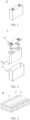
- FIG. 1 is a schematic diagram of a secondary battery 5 of a square structure as an example, and FIG. 1 is an exploded view of the secondary battery 5.
- the outer package may include a housing 51 and a cover plate 53.
- the housing 51 may include a base plate and side plates connected to the base plate, and the base plate and the side plates enclose an accommodating cavity.
- the housing 51 has an opening communicating with the accommodating cavity, and the cover plate 53 can cover the opening to close the accommodating cavity.
- the positive electrode plate, the negative electrode plate, and the separator may be made into an electrode assembly 52 through winding or lamination.
- the electrode assembly 52 is packaged in the accommodating cavity.
- An electrolyte solution infiltrates the electrode assembly 52.
- the secondary battery 5 may include one or more electrode assemblies 52, and persons skilled in the art may make choices according to actual requirements.
- the secondary battery may be assembled into a battery module, and the battery module may include one or more secondary batteries.
- a specific quantity may be chosen by persons skilled in the art according to use and capacity of the battery module.
- FIG. 3 shows a battery module 4 as an example.
- a plurality of secondary batteries 5 may be sequentially arranged in a length direction of the battery module 4.
- the secondary batteries may alternatively be arranged in any other manners.
- the plurality of secondary batteries 5 may be fastened using fasteners.
- the battery module 4 may further include a housing with an accommodating space, and the plurality of secondary batteries 5 are accommodated in the accommodating space.
- the battery module may be further assembled into a battery pack, and the battery pack may include one or more battery modules.
- a specific quantity may be chosen by persons skilled in the art based on use and capacity of the battery pack.
- FIG. 4 and FIG. 5 show a battery pack 1 as an example.
- the battery pack 1 may include a battery box and a plurality of battery modules 4 arranged in the battery box.
- the battery box includes an upper box body 2 and a lower box body 3.
- the upper box body 2 can cover the lower box body 3 to form an enclosed space for accommodating the battery modules 4.
- the plurality of battery modules 4 may be arranged in the battery box in any manner.
- this application further provides an electric apparatus.
- the electric apparatus includes at least one of the secondary battery, the battery module, or the battery pack provided in this application.
- the secondary battery, the battery module, or the battery pack may be used as a power source for the electric apparatus, or as an energy storage unit of the electric apparatus.
- the electric apparatus may include a mobile device (for example, a mobile phone or a notebook computer), an electric vehicle (for example, a battery electric vehicle, a hybrid electric vehicle, a plug-in hybrid electric vehicle, an electric bicycle, an electric scooter, an electric golf vehicle, or an electric truck), an electric train, a ship, a satellite system, an energy storage system, or the like, but is not limited thereto.
- a secondary battery, a battery module, or a battery pack may be selected according to requirements for using the electric apparatus.
- FIG. 6 shows an electric apparatus as an example.
- This electric apparatus is a battery electric vehicle, a hybrid electric vehicle, a plug-in hybrid electric vehicle, or the like.
- a battery pack or a battery module may be used.
- the apparatus may be a mobile phone, a tablet computer, a notebook computer, or the like.
- the apparatus is usually required to be light and thin and may use a secondary battery as a power supply.
- Inorganic solid electrolyte powder Na 3.4 Zr 1.9 Zn 0.1 Si 2.2 P 0.8 O 12 with a particle size of 20 ⁇ m and 20wt.% carbon black were mixed to uniformity to obtain a powder mixture; and part of the powder mixture was laid in a mold and flattened at 20 MPa to obtain a porous layer precursor.
- the inorganic solid electrolyte powder Na 3.4 Zr 1.9 Zn 0.1 Si 2.2 P 0.8 O 12 with a particle size of 20 ⁇ m was laid on the porous layer precursor and flattened at 20 MPa to obtain a compact layer.
- the remaining powder mixture was laid on the compact layer and flattened at 20 MPa pressure to obtain a porous layer precursor.
- porous layer precursor, the compact layer, and the other porous layer precursor were flattened at 200 MPa to obtain a solid electrolyte precursor, where a mass of the compact layer accounted for 60% of a total mass of the solid electrolyte precursor.
- the solid electrolyte precursor was put into a muffle furnace, maintained at a temperature of 500°C for 3 h, and then maintained at a temperature of 1000°C for 20 h to obtain a solid electrolyte of a three-layer structure.
- a thickness of the compact layer was 0.4 mm, thicknesses of the porous layers on two sides of the compact layer were both 0.6 mm, and a thickness ratio of the porous layer to the compact layer was 1.5.
- a contact angle of molten sodium on the porous layer of the solid electrolyte was 65°, and a contact angle of molten sodium on the compact layer of the solid electrolyte was 89°.
- Carbon nanotubes and carboxymethyl cellulose (CMC) at a mass ratio of 1:0.4 were added to deionized water and stirred to form a uniform slurry; the slurry was applied onto a surface of a positive electrode current collector aluminum foil; and subsequently, the aluminum foil was transferred into a vacuum drying oven to be dried completely, and then punched to obtain a positive electrode plate with no positive electrode structure.
- CMC carboxymethyl cellulose
- Carbon nanotubes and carboxymethyl cellulose (CMC) at a mass ratio of 1:0.4 were added to deionized water and stirred to form a uniform slurry; the slurry was applied onto a surface of a negative electrode current collector copper foil; and subsequently the copper foil was transferred into a vacuum drying oven to be dried completely, and then punched to obtain a positive electrode plate with no positive electrode structure, where an areal density of the primer layer was 10 g/m 2 , and a thickness of the primer layer was 5 ⁇ m.
- a polypropylene film was used as a separator.
- Carbon-coated sodium iron pyrophosphate (Na 4 Fe 3 (PO 4 ) 2 P 2 O 7 /C) with a particle size of less than 10 ⁇ m was first dispersed in an ethylene glycol dimethyl ether solvent using an impregnation method; and then an impregnation method was used to allow the positive electrode active material carbon-coated sodium iron pyrophosphate (Na 4 Fe 3 (PO 4 ) 2 P 2 O 7 /C) to enter the porous layer on the positive electrode side and fill the corresponding pores.
- carbon nanotubes were dispersed in the ethylene glycol dimethyl ether solvent, then the solvent was dropwise added onto the porous layer of the solid electrolyte on the negative electrode plate side by using the impregnation method, and the porous layer was impregnated for more than 5 h and heated at 60°C, such that the carbon nanotubes could enter the porous layer of the solid electrolyte on the negative electrode side and fill the corresponding pores.
- the positive electrode plate, the solid electrolyte, and the negative electrode plate were stacked sequentially and then wound to obtain a jelly roll; tabs were welded to the jelly roll; the jelly roll was packaged into an aluminum housing and baked at 80°C to remove moisture; and then the aluminum housing was sealed to obtain an uncharged battery.
- the uncharged battery was then sequentially subjected to processes such as standing, hot and cold pressing, formation, shaping, and capacity testing to obtain the sodium secondary battery product with no negative electrode of Example 1.
- a preparation method of a battery of Example 2 was similar to that of the battery of Example 1, except that the type of the solid electrolyte was adjusted, where specific parameters are shown in Table 1.
- Example 3 shows a sodium metal secondary battery whose preparation method was basically the same as that of Example 2, except that the pores of the porous layer of the solid electrolyte on the negative electrode plate side were infused with sodium metal using a thermal infusion method, where specific parameters are shown in Table 1.
- Examples 4 and 5 show a sodium metal secondary battery whose preparation method was basically the same as that of Example 3, except that in Example 4, the porous layer on the negative electrode side was infused with sodium-potassium-lithium alloy in which a mass ratio of sodium to potassium to lithium was 2:3:5, and in Example 5, the porous layer on the negative electrode side was infused with sodium-potassium alloy in which a mass ratio of sodium to potassium was 2:3, where specific parameters are shown in Table 1.
- Example 6 A preparation method of Example 6 was basically the same as that of Example 1, except that the type of the solid electrolyte was adjusted, where specific parameters are shown in Table 1.
- a preparation method of Examples 7 and 8 was basically the same as that of Example 1, except that the type of the positive electrode active material was adjusted, where in Example 8, a thickness of the coating layer was 30 nm, and specific parameters are shown in Table 1.
- Examples 9 to 11 show a sodium metal secondary battery whose preparation method was basically the same as that of Example 1, except that in Example 9, the pores of the porous layer of the solid electrolyte on the negative electrode plate side was infused with sodium metal using a thermal infusion method, in Example 10, the porous layer on the negative electrode side was infused with sodium-potassium-lithium alloy in which a mass ratio of sodium to potassium to lithium was 2:3:5; and in Example 11, the porous layer on the negative electrode side was infused with sodium-potassium alloy in which a mass ratio of sodium to potassium was 2:3; where specific parameters are shown in Table 1.
- a preparation method of Examples 12 to 19 was basically the same as that of Example 1, except that the thickness ratio of the porous layer to the compact layer or the ionic conductivity ratio of the porous layer to the compact layer was adjusted, where specific parameters are shown in Table 2.
- a preparation method of Example 20 was basically the same as that of Example 1, except that a slurry prepared by mixing a positive electrode active material with a conductive agent was applied onto a current collector of the positive electrode plate, where specific parameters are shown in Table 1.
- Example 21 A preparation method of Example 21 was basically the same as that of Example 9, except that a slurry prepared by mixing a positive electrode active material with a conductive agent was applied onto a current collector of the positive electrode plate, where specific parameters are shown in Table 2.
- a preparation method of Example 22 was basically the same as that of Example 10, except that a slurry prepared by mixing a positive electrode active material with a conductive agent was applied onto a current collector of the positive electrode plate, where specific parameters are shown in Table 2.
- a preparation method of Example 23 was basically the same as that of Example 11, except that a slurry prepared by mixing a positive electrode active material with a conductive agent was applied onto a current collector of the positive electrode plate, where specific parameters are shown in Table 2.
- a preparation method of Examples 24 to 27 was basically the same as that of Example 1, except that the solid electrolyte in Examples 24 to 27 was provided with the porous layer on only one side of the compact layer, that was, the solid electrolyte included only the porous layer on the positive electrode plate side, the positive electrode active material was distributed in the porous layer, the thicknesses of the porous layer and the compact layer were the same as the thickness of each layer of the solid electrolyte in Example 1, and the negative electrode plate and the compact layer of the solid electrolyte were assembled with contact, where specific parameters are shown in Table 2.
- a preparation method of a battery in Comparative examples 1 to 8 was basically the same as that of Example 1, except that the solid electrolyte included only one compact layer, and the thickness of the compact layer was the same as the thickness of the compact layer of the solid electrolyte in Example 1.
- a porous layer sheet and a compact layer sheet were respectively subjected to an electrochemical alternating-current impedance test.
- Test processes of the comparative examples and other examples were the same as above.
- Molten sodium was dropwise added to the surface of the solid electrolyte, then an image of the surface of the electrolyte was taken using a high-resolution camera (Grasshopper GRAS-50S5M-C) equipped with a Fujinon HF75SA-1 lens, and a contact angle was measured using ImageJ software. Test processes of the comparative examples and other examples were the same as above.
- a nucleation overpotential test process was as follows: At 25°C, in a three-electrode battery system, an aluminum current collector coated with carbon nanotubes was used as a working electrode, a sodium metal sheet was used as a counter electrode, another sodium metal sheet was used as a reference electrode, the battery was discharged to 0.3 mAh/cm 2 at a constant current of 0.1 mA/cm 2 , and the most negative potential obtained in this process was recorded as a nucleation overpotential. Test processes of the comparative examples and other examples were the same as above.
- a room-temperature/low-temperature cycling performance test was as follows: At 25°C/-10°C, the prepared battery was charged to 3.7 V (a carbon-coated sodium iron pyrophosphate positive electrode material) or to 4.0 V (a layered transition metal oxide positive electrode material) at a constant current of 1C, and then discharged to 2.5 V at 1C, and a capacity obtained was recorded as an initial capacity (C0).
- Test processes of the comparative examples and other examples were the same as above.
- An interface resistance test process was as follows: An assembled full battery was subjected to an electrochemical alternating-current impedance test. At 25°C, an alternating-current impedance spectrum of the full battery was measured using a 1470 multi-channel electrochemical workstation from Solartron in UK, where a frequency range was 1 Hz to 1 MHz, and a perturbation signal was 5 mV. After the relevant electrochemical impedance spectrum was obtained, fitting was performed using Zview software, and a diameter obtained by fitting an arc whose impedance tolerance value was between 1 ⁇ 10 -7 and 1 ⁇ 10 -5 was taken as an interface resistance. Test processes of the comparative examples and other examples were the same as above.
- the solid electrolytes for secondary batteries in Examples 1 to 27 each include a compact layer and a porous layer located on at least one side of the compact layer, and the porosity of the porous layer is greater than the porosity of the compact layer.
- the solid electrolyte in this application that includes a compact layer and a porous layer located on at least one side of the compact layer helps to significantly increase the number of cycles when the capacity of the battery reaches 80% at 25°C and -10°C, reduce the interface resistance of the battery, and significantly increase the charge/discharge rate at 50% of the discharge capacity at 1C.
- Example 1 From the comparison between Example 1 and Examples 2 and 6, it can be seen that compared with an inorganic solid electrolyte material including ⁇ -Na 2 O ⁇ 11Al 2 O 3 or Na 11 Sn 2 P 2 S 12 , the inorganic solid electrolyte material including Na 3.4 M 1.9 M' 0.1 Si 2.2 P 0.8 O 12 further helps to reduce the nucleation overpotential of the battery and increase the number of cycles when the capacity of the battery reaches 80% at 25°C and -10°C.
- Example 1 From the comparison between Example 1 and Examples 7 and 8, it can be seen that compared with using Na 2/3 Ni 1/6 Mn 2/3 Cu 1/9 Mg 1/18 O 2 or Na(Cu 1/9 Ni 2/9 Fe 1/3 Mn 1/3 )O 2 coated with ZrO 2 or TiO 2 as the positive electrode active material, using Na 4 Fe 3 (PO 4 ) 2 P 2 O 7 as the positive electrode active material helps to increase the number of cycles when the capacity of the battery reaches 80% at 25°C and -10°C, reduce the interface resistance of the battery, and increase the charge/discharge rate at 50% of the discharge capacity at 1C.
- Example 8 From the comparison between Example 8 and Example 7, it can be seen that compared with using Na(Cu 1/9 Ni 2/9 Fe 1/3 Mn 1/3 )O 2 as the positive electrode active material, using Na 2/3 Ni 1/6 Mn 2/3 Cu 1/9 Mg 1/18 O 2 coated with ZrO 2 or TiO 2 as the positive electrode active material helps to increase the number of cycles when the capacity of the battery reaches 80% at 25°C and -10°C.
- Example 1 and Example 24 From the comparison between Example 1 and Example 24, the comparison between Example 9 and Example 25, the comparison between Example 10 and Example 26, the comparison between Example 11 and Example 27, it can be seen that for a sodium secondary battery with no negative electrode or a sodium metal secondary battery, compared with a solid electrolyte that includes a compact layer and a porous layer located on a positive electrode plate side, the solid electrolyte that includes a compact layer, a porous layer located on a positive electrode plate side and a porous layer located on a negative electrode plate side helps to reduce the nucleation overpotential of the battery, increase the number of cycles when the capacity of the battery reaches 80% at 25°C and -10°C, reduce the interface resistance of the battery, and increase the charge/discharge rate at 50% of the discharge capacity at 1C.
- Example 9 From the comparison between Example 9 and Example 3, the comparison between Example 10 and Example 4, and the comparison between Example 111 and Example 5, it can be seen that for a sodium metal secondary battery, compared with an inorganic solid electrolyte material including ⁇ -Na 2 O ⁇ 11Al 2 O 3 , the inorganic solid electrolyte material including Na 3.4 M 1.9 M' 0.1 Si 2.2 P 0.8 O 12 further helps to reduce the nucleation overpotential of the battery, increase the number of cycles when the capacity of the battery reaches 80% at 25°C and -10°C, reduce the interface resistance of the battery, and increase the charge/discharge rate at 50% of the discharge capacity at 1C.
- Example 1 and Example 20 From the comparison between Example 1 and Example 20, the comparison between Example 9 and Example 21, the comparison between Example 10 and Example 22, and the comparison between Example 111 and Example 23, it can be seen that for a sodium metal secondary battery, compared with a manner in which the positive electrode slurry is prepared from a positive electrode active material Na 3.4 M 1.9 M' 0.1 Si 2.2 P 0.8 O 12 and a conductive agent and applied onto a current collector, the manner in which the pores of the porous layer in contact with the positive electrode plate are filled with a positive electrode active material Na 3.4 M 1.9 M' 0.1 Si 2.2 P 0.8 O 12 further helps to increase the number of cycles when the capacity of the battery reaches 80% at 25°C and -10°C, reduce the interface resistance of the battery, and increase the charge/discharge rate at 50% of the discharge capacity at 1C.
- controlling the ionic conductivity of the porous layer to be not less than 1/10 of the ionic conductivity of the compact layer helps to reduce the nucleation overpotential of the battery, increase the number of cycles when the capacity of the battery reaches 80% at 25°C and -10°C, reduce the interface resistance of the battery, and increase the charge/discharge rate at 50% of the discharge capacity at 1C.
Landscapes
- Chemical & Material Sciences (AREA)
- Chemical Kinetics & Catalysis (AREA)
- Electrochemistry (AREA)
- General Chemical & Material Sciences (AREA)
- Engineering & Computer Science (AREA)
- Inorganic Chemistry (AREA)
- Manufacturing & Machinery (AREA)
- Composite Materials (AREA)
- Materials Engineering (AREA)
- Physics & Mathematics (AREA)
- Condensed Matter Physics & Semiconductors (AREA)
- General Physics & Mathematics (AREA)
- Crystallography & Structural Chemistry (AREA)
- Secondary Cells (AREA)
- Conductive Materials (AREA)
- Cell Electrode Carriers And Collectors (AREA)
- Battery Electrode And Active Subsutance (AREA)
Applications Claiming Priority (2)
| Application Number | Priority Date | Filing Date | Title |
|---|---|---|---|
| CN202310070432.9A CN118352610A (zh) | 2023-01-16 | 2023-01-16 | 固态电解质、及其制备方法、二次电池、电池模块、电池包及用电装置 |
| PCT/CN2023/132362 WO2024152721A1 (zh) | 2023-01-16 | 2023-11-17 | 固态电解质、及其制备方法、二次电池、电池模块、电池包及用电装置 |
Publications (2)
| Publication Number | Publication Date |
|---|---|
| EP4564509A1 true EP4564509A1 (de) | 2025-06-04 |
| EP4564509A4 EP4564509A4 (de) | 2026-01-07 |
Family
ID=91819965
Family Applications (1)
| Application Number | Title | Priority Date | Filing Date |
|---|---|---|---|
| EP23917189.5A Pending EP4564509A4 (de) | 2023-01-16 | 2023-11-17 | Festkörperelektrolyt, herstellungsverfahren dafür, sekundärbatterie, batteriemodul, batteriepack und elektrische vorrichtung |
Country Status (6)
| Country | Link |
|---|---|
| US (1) | US20250201915A1 (de) |
| EP (1) | EP4564509A4 (de) |
| JP (1) | JP2025530804A (de) |
| KR (1) | KR20250035593A (de) |
| CN (1) | CN118352610A (de) |
| WO (1) | WO2024152721A1 (de) |
Cited By (1)
| Publication number | Priority date | Publication date | Assignee | Title |
|---|---|---|---|---|
| EP4528874A4 (de) * | 2023-01-17 | 2026-03-25 | Contemporary Amperex Technology Hong Kong Ltd | Festelektrolyt, sekundärbatterie, batteriemodul, batteriepack und elektrische vorrichtung |
Families Citing this family (2)
| Publication number | Priority date | Publication date | Assignee | Title |
|---|---|---|---|---|
| CN119253033B (zh) * | 2024-09-04 | 2025-09-16 | 华中科技大学 | 一种多孔固态电解质的制备方法及其应用 |
| CN119627195A (zh) * | 2024-12-11 | 2025-03-14 | 远景动力技术(江苏)有限公司 | 一种全固态电池及其应用 |
Family Cites Families (13)
| Publication number | Priority date | Publication date | Assignee | Title |
|---|---|---|---|---|
| JP4925878B2 (ja) * | 2007-03-22 | 2012-05-09 | 日本碍子株式会社 | セラミックス構造体の製造方法 |
| JP5740297B2 (ja) * | 2011-12-22 | 2015-06-24 | 株式会社日立製作所 | リチウムイオン二次電池用正極、リチウムイオン二次電池、これを搭載した乗り物および電力貯蔵システム |
| JP2016517146A (ja) * | 2013-03-21 | 2016-06-09 | ユニバーシティー オブ メリーランド、カレッジ パーク | 固体電解質物質を含むイオン伝導性バッテリー |
| US20210257658A1 (en) * | 2013-03-21 | 2021-08-19 | University Of Maryland, College Park | Solid-state li-s batteries and methods of making same |
| EP3384545A4 (de) * | 2015-11-30 | 2019-07-10 | University of Maryland, College Park | Festkörper-li-s-batterien und verfahren zur herstellung davon |
| KR102358448B1 (ko) * | 2017-11-21 | 2022-02-04 | 주식회사 엘지에너지솔루션 | 리튬 이차전지용 음극 및 이의 제조 방법 |
| KR102144284B1 (ko) * | 2018-11-23 | 2020-08-13 | 연세대학교 산학협력단 | 고체전해질 구조체, 이를 포함하는 소듐 이차전지 및 고체전해질의 표면처리 방법 |
| DE102019000841A1 (de) * | 2019-02-06 | 2020-08-06 | Forschungszentrum Jülich GmbH | Festkörperbatterie sowie Verfahren zur Herstellung derselben |
| CN111313087B (zh) * | 2019-06-05 | 2021-10-01 | 北京纳米能源与系统研究所 | 电解质材料、钠离子固体电解质及应用和钠离子固体电池 |
| CN116259710A (zh) * | 2020-10-15 | 2023-06-13 | 宁德新能源科技有限公司 | 极片及包含其的电化学装置和电子设备 |
| US20220263070A1 (en) * | 2021-02-15 | 2022-08-18 | Global Graphene Group, Inc. | Solid-state medium for lithium ion transport, lithium batteries and manufacturing method |
| CN113451546B (zh) * | 2021-06-26 | 2022-05-06 | 宁德时代新能源科技股份有限公司 | 钠金属电池、电化学装置 |
| CN115172864B (zh) * | 2022-07-06 | 2025-08-29 | 北京新能源汽车股份有限公司 | 固态电池及其制备方法和应用 |
-
2023
- 2023-01-16 CN CN202310070432.9A patent/CN118352610A/zh active Pending
- 2023-11-17 JP JP2025513396A patent/JP2025530804A/ja active Pending
- 2023-11-17 KR KR1020257005957A patent/KR20250035593A/ko active Pending
- 2023-11-17 EP EP23917189.5A patent/EP4564509A4/de active Pending
- 2023-11-17 WO PCT/CN2023/132362 patent/WO2024152721A1/zh not_active Ceased
-
2025
- 2025-03-03 US US19/068,624 patent/US20250201915A1/en active Pending
Cited By (1)
| Publication number | Priority date | Publication date | Assignee | Title |
|---|---|---|---|---|
| EP4528874A4 (de) * | 2023-01-17 | 2026-03-25 | Contemporary Amperex Technology Hong Kong Ltd | Festelektrolyt, sekundärbatterie, batteriemodul, batteriepack und elektrische vorrichtung |
Also Published As
| Publication number | Publication date |
|---|---|
| WO2024152721A1 (zh) | 2024-07-25 |
| EP4564509A4 (de) | 2026-01-07 |
| KR20250035593A (ko) | 2025-03-12 |
| JP2025530804A (ja) | 2025-09-17 |
| CN118352610A (zh) | 2024-07-16 |
| US20250201915A1 (en) | 2025-06-19 |
Similar Documents
| Publication | Publication Date | Title |
|---|---|---|
| EP3098882B1 (de) | Elektrische vorrichtung | |
| EP4564509A1 (de) | Festkörperelektrolyt, herstellungsverfahren dafür, sekundärbatterie, batteriemodul, batteriepack und elektrische vorrichtung | |
| US10535870B2 (en) | Electrical device | |
| CN115832166B (zh) | 正极极片、二次电池、电池模块、电池包和用电装置 | |
| US20160308243A1 (en) | Electrochemical cell with solid and liquid electrolytes | |
| EP3098892B1 (de) | Elektrische vorrichtung | |
| JPWO2017046915A1 (ja) | 二次電池用複合電解質、二次電池及び電池パック | |
| JP2015156356A (ja) | 水溶液電解質ナトリウムイオン二次電池、および、これを含む充放電システム | |
| CN117790793A (zh) | 用于高能量电池的混合电极设计 | |
| Mae et al. | A stable full cell having high energy density realized by using a three-dimensional current collector of carbon nanotubes and partial prelithiation of silicon monoxide | |
| EP3098890B1 (de) | Elektrische vorrichtung | |
| US12206091B2 (en) | Lithium molybdate anode material | |
| US20250343269A1 (en) | Electrolyte, secondary battery, and electrical apparatus | |
| US20250350005A1 (en) | Composite separator, secondary battery, and power consuming apparatus | |
| CN118825212B (zh) | 钠金属电池的正极活性材料、正极极片、电池单体、钠金属电池及用电装置 | |
| EP4468393A1 (de) | Natrium-ionen-batterie und elektrische vorrichtung damit | |
| JP2025537865A (ja) | 集電体、二次電池、電池モジュール、電池パック及び電気装置 | |
| US20220393148A1 (en) | Negative electrode and nonaqueous electrolyte secondary battery including the same | |
| JP2025533141A (ja) | 集電体およびその応用、二次電池、電池モジュール、電池パック並びに電力消費機器 | |
| US20240290962A1 (en) | Free-standing, three-dimensional (3d) anode having continuous, ion-conducting network | |
| EP4586354A1 (de) | Stromabnehmer, sekundärbatterie, batteriemodul, batteriepack und elektrische vorrichtung | |
| US20250219068A1 (en) | Freestanding lithium-alloy anodes for lithium-sulfur batteries | |
| EP4597675A1 (de) | Elektrolyt für natriumsekundärbatterie, natriumsekundärbatterie und elektrische vorrichtung | |
| WO2025040586A1 (en) | Coated cathode active material for lithium ion batteries | |
| CN121215861A (zh) | 二次电池、用电装置以及正极活性材料的制备方法 |
Legal Events
| Date | Code | Title | Description |
|---|---|---|---|
| STAA | Information on the status of an ep patent application or granted ep patent |
Free format text: STATUS: THE INTERNATIONAL PUBLICATION HAS BEEN MADE |
|
| PUAI | Public reference made under article 153(3) epc to a published international application that has entered the european phase |
Free format text: ORIGINAL CODE: 0009012 |
|
| STAA | Information on the status of an ep patent application or granted ep patent |
Free format text: STATUS: REQUEST FOR EXAMINATION WAS MADE |
|
| 17P | Request for examination filed |
Effective date: 20250226 |
|
| AK | Designated contracting states |
Kind code of ref document: A1 Designated state(s): AL AT BE BG CH CY CZ DE DK EE ES FI FR GB GR HR HU IE IS IT LI LT LU LV MC ME MK MT NL NO PL PT RO RS SE SI SK SM TR |
|
| A4 | Supplementary search report drawn up and despatched |
Effective date: 20251209 |
|
| RIC1 | Information provided on ipc code assigned before grant |
Ipc: H01M 10/0562 20100101AFI20251203BHEP Ipc: H01M 10/0561 20100101ALI20251203BHEP Ipc: H01M 10/056 20100101ALI20251203BHEP Ipc: H01M 10/0525 20100101ALI20251203BHEP Ipc: H01M 10/054 20100101ALI20251203BHEP |
|
| DAV | Request for validation of the european patent (deleted) | ||
| DAX | Request for extension of the european patent (deleted) |