EP4564540A1 - Energiespeicherzelle mit vorgeschnittener entlüftungsmembran - Google Patents
Energiespeicherzelle mit vorgeschnittener entlüftungsmembran Download PDFInfo
- Publication number
- EP4564540A1 EP4564540A1 EP23307121.6A EP23307121A EP4564540A1 EP 4564540 A1 EP4564540 A1 EP 4564540A1 EP 23307121 A EP23307121 A EP 23307121A EP 4564540 A1 EP4564540 A1 EP 4564540A1
- Authority
- EP
- European Patent Office
- Prior art keywords
- venting
- precut
- energy storage
- venting membrane
- membrane
- Prior art date
- Legal status (The legal status is an assumption and is not a legal conclusion. Google has not performed a legal analysis and makes no representation as to the accuracy of the status listed.)
- Pending
Links
Images


Classifications
-
- H—ELECTRICITY
- H01—ELECTRIC ELEMENTS
- H01M—PROCESSES OR MEANS, e.g. BATTERIES, FOR THE DIRECT CONVERSION OF CHEMICAL ENERGY INTO ELECTRICAL ENERGY
- H01M50/00—Constructional details or processes of manufacture of the non-active parts of electrochemical cells other than fuel cells, e.g. hybrid cells
- H01M50/30—Arrangements for facilitating escape of gases
- H01M50/342—Non-re-sealable arrangements
- H01M50/3425—Non-re-sealable arrangements in the form of rupturable membranes or weakened parts, e.g. pierced with the aid of a sharp member
-
- H—ELECTRICITY
- H01—ELECTRIC ELEMENTS
- H01M—PROCESSES OR MEANS, e.g. BATTERIES, FOR THE DIRECT CONVERSION OF CHEMICAL ENERGY INTO ELECTRICAL ENERGY
- H01M50/00—Constructional details or processes of manufacture of the non-active parts of electrochemical cells other than fuel cells, e.g. hybrid cells
- H01M50/10—Primary casings; Jackets or wrappings
- H01M50/102—Primary casings; Jackets or wrappings characterised by their shape or physical structure
- H01M50/103—Primary casings; Jackets or wrappings characterised by their shape or physical structure prismatic or rectangular
-
- H—ELECTRICITY
- H01—ELECTRIC ELEMENTS
- H01M—PROCESSES OR MEANS, e.g. BATTERIES, FOR THE DIRECT CONVERSION OF CHEMICAL ENERGY INTO ELECTRICAL ENERGY
- H01M50/00—Constructional details or processes of manufacture of the non-active parts of electrochemical cells other than fuel cells, e.g. hybrid cells
- H01M50/10—Primary casings; Jackets or wrappings
- H01M50/147—Lids or covers
- H01M50/148—Lids or covers characterised by their shape
- H01M50/15—Lids or covers characterised by their shape for prismatic or rectangular cells
Definitions
- the present invention concerns an energy storage cell of the type comprising:
- An energy storage cell is an assembly that enables electrical energy to be converted into chemical energy and then stored. It comprises a set of multiple electrode sheets stacked and immersed in an electrolyte.
- the formation and/or expansion of gases produced during operation may increase the internal pressure of the cell. If the internal pressure reaches a critical point by any chance, it can cause the cell to explode. To avoid explosion of the cell, a slightly deformable and tearable leak-tight venting membrane is used across a venting window of the cell.
- the internal pressure inside the cell increases to a point where the accommodation in changes in pressure provided by the deformation of the venting membrane is not sufficient to protect the cell and to avoid its subsequent explosion.
- the venting membrane comprises a precut pattern, delimiting a region of the venting membrane where the mechanical properties are inferior.
- the venting membrane tends to rip along the precut pattern causing the membrane to open, and the gases are ejected from the internal volume of the cell through the opened venting membrane. The remaining elements of the cell are therefore protected.
- the precut pattern is commonly found in the literature as a central double Y line, allowing the venting membrane to open in two opposite flaps. This line is straight and is extended by two diverging segments at each end. The gases are thus allowed to escape the cell perpendicularly to the venting window, through an opening defined between the two ripped edges, which is parallel to the initial plan of the venting member.
- an energy storage cell is commonly used with several other energy storage cells, forming together an energy storage cell pack or module closed by a cover.
- the cover is located around the cells and in particular above the venting window. Therefore, after the opening of the membrane, the ripped edges are pressed against the cover. The cover forms thus an obstacle to the circulation of the gases escaping the cell in case of tearing of the venting membrane.
- One aim of the invention is therefore to propose a better protection of the cell in case of high internal pressure by allowing a better escape of the gases from the storage cell.
- the energy storage cell is characterized in that the precut pattern defines a convex movable flap on one side, and a concave complementary panel on the other side, the convex movable flap being movable with respect to the concave complementary panel so as to form an opening between ripped edges of the convex movable flap and the concave complementary panel in the opened position of the venting membrane, the opening extending slightly perpendicular to the initial plane of the venting membrane.
- the venting membrane deforms until being ripped in the region of the precut pattern.
- the convex movable flap together with the concave complementary panel forms an opening for the gases circulation which is slightly perpendicular to the cover and which is thus not closed by the cover.
- the gases are ejected from the cell through the opening in a direction slightly parallel to the venting window.
- the cover is therefore not on the circulating path of the ejected gases anymore and does not slow down the depressurization process. Therefore, the cell is better protected in case of high internal pressure conditions.
- the energy storage cell according to the invention comprises one or more of the following features, taken alone or in any technically possible combination:
- the invention concerns an energy storage cell pack or module comprising an array of energy storage cells as described above, and a cover facing the venting face of each energy storage cell.
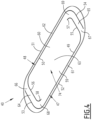
- the energy storage cell 10 shown in Figures 1 and 2 comprises a can 13 defining a closed internal volume 15.
- the can 13 is for example a metallic parallelepipedal case.
- the energy storage cell 10 comprises two stacks of electrodes 18 enclosed in the closed internal volume 15.
- the can 13 Before operation of the energy storage cell 10, the can 13 is filled with an electrolyte in which the stacks of electrodes 18 are immersed.
- the stacks of electrodes 18 are parallelepipedal in shape and are completely enclosed for electrical insulation by a protective envelope 21.
- Each energy storage cell 10 comprises connection tabs 22 connecting together the electrodes of the same polarity.
- the connection tabs 22 are electrically connected to respective outer connection terminals 23 through collectors 24.
- the can 13 comprises a venting face 25 on which the terminals 23 are exposed.
- An oblong pass-through venting window 30, represented in Figure 3 allowing the passage of gas from the closed internal volume 15 is defined in the venting face 25.
- the venting face 25 is the top face of the can 13.
- the venting face 25 could also be a lateral face, or a bottom face of the can 13.
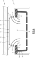
- the venting face 25 comprises an external layer 33 superimposed with an internal layer 36, as shown in Figure 3 .
- the pass-through venting window 30 extends across both the external layer 33 and the internal layer 36.
- the pass-through venting window 30 allows the passage of gas and electrolytes from the internal volume 15 of the can 13 towards the outside of the energy storage cell 10.
- the energy storage cell 10 comprises a venting membrane 40 laid across the pass-through venting window 30.
- the venting membrane 40 has an oblong outline.
- the venting membrane 40 is leak-tight.
- the venting membrane 40 is a sheet of aluminum, having a thickness comprised between 0.2 mm and 0.5 mm.
- the venting membrane 40 is welded around the perimeter of the pass-through venting window 30, and sealingly closes the pass-through venting window 30.
- the venting membrane 40 is for example welded on an inner face of the can 13.
- venting membrane 40 is fixed to the external layer 33 of the venting face 25.
- venting membrane 40 is welded on an inner face 33A of the external layer 33 of the venting face 25 by a weld 41.
- the external layer 33 of the venting face 25 comprises a peripheral shoulder 43 with reduced thickness around the pass-through venting window 30.
- the peripheral shoulder 43 extends along the entire perimeter of the pass-through venting window 30.
- the venting membrane 40 is welded on the inner side of the peripheral shoulder 43.
- the venting membrane 40 is slightly deformable.
- venting membrane 40 is able to be deflected in a concave manner towards the inside of the cell 10 in response to a low-pressure condition inside the cell 10 and/or a high-pressure condition outside the cell 10.
- venting membrane 40 is able to be deflected in a convex manner towards the outside of the cell 10 in response to a high-pressure condition inside the cell 10 and/or a low-pressure condition outside the cell 10.
- the venting membrane 40 comprises two precut patterns 47, 48 allowing the venting membrane 40 to deform between a closing position wherein the venting membrane 40 extends on an initial plane and sealingly closes the venting window 30, and an opened position wherein the venting membrane 40 is ripped and allows the passage of gas.
- the initial plane corresponds to the plane onto which the venting membrane 40 lays when the venting membrane 40 is in the closing position.
- a precut pattern is for example a region of the venting membrane 40 where the thickness is reduced. Therefore, when the venting membrane 40 faces a high internal pressure and tends to deform consequently, the region of the precut patterns 47, 48, being mechanically less resistant, will rip and the venting membrane 40 will open according to the precut patterns.
- the thickness of the venting membrane 40 in the regions of the precut patterns 47, 48 is roughly comprised between about 40% and 70% of the thickness of the venting membrane 40 away from the precut patterns 47, 48.
- each precut pattern 47, 48 is a convex line, more particularly each precut pattern 47, 48 is a sensibly U-shaped line.
- Each U-shaped line respectively comprises a median section 49, 50 parallel to longitudinal edges 51, 52 of the venting membrane 40 and two lateral sections 53, 54, 55, 56 on either side of the median section 49, 50.
- the lateral sections 53, 54, 55, 56 extend from one longitudinal edge 51, 52 to the other, and extend parallel to each other.
- the median sections 49, 50 have substantially the same length, and the lateral sections 53, 54, 55, 56 have substantially the same length as well.
- the median part 49, 50 of each precut pattern 47, 48 is respectively located in the vicinity of a longitudinal edge 51, 52 of the venting membrane 40.
- the lengths of the median sections 49, 50 and the lateral sections 53, 54, 55, 56 are more than 70% of the length and the width of the membrane, respectively.
- the two precut patterns 47, 48 are interlocked, in such a way that the U-shaped line of a first precut pattern 47 and the U-shaped line of a second precut pattern 48 are curved in opposite directions.
- each precut pattern 47, 48 comprises an outer lateral section 53, 54 being outside the U-shaped line formed by the other precut pattern 48, 47, and an inner lateral section 55, 56 being inside the U-shaped line formed by the other precut pattern 48, 47.
- each precut pattern 47, 48 comprises a curved portion 57, 58 extending the U-shaped lines towards the centre of the venting membrane 40.
- the curved portions 57, 58 extend the respective inner lateral sections 55, 56 towards the centre of the venting membrane 40.
- Each precut pattern 47, 48 defines respectively a convex movable flap 59, 60 on one side, and a concave complementary panel 61, 62 on the other side.
- each convex movable flap 59, 60 independently from the other, the area defined by each convex movable flap 59, 60 is strictly greater than the area defined by the respective concave complementary panel 61, 62.
- the two precut patterns 47, 48 are interlocked in such a way that more than 60% of the area of the first movable flap 59 is shared with the area of the second movable flap 60.
- the shared area between each movable flap 59, 60 is commonly defined in what follows as a venting region 63.
- the shared portion of the convex movable flaps 59, 60 delimits the venting region 63, the venting region 63 being moved away from the complementary panels 61, 62, while the unshared portions of the convex movable flaps 59, 60 delimit two partially movable legs 64, 65.
- the partially movable legs 64, 65 allow the venting region 63 to be displaced from the initial plane of the venting membrane 40 in order to allow gas circulation, while maintaining the venting region 63 connected to the fixed part of the venting membrane 40.
- first convex movable flap 59 which is not shared with the second convex movable flap 60 delimits a first partially movable leg 64.
- the portion of the second convex movable flap 60 which is not shared with the first convex movable flap 59 delimits a second partially movable leg 65.
- Each partially movable leg 64, 65 is partially movable with respect to a fixed portion of the venting membrane 40.
- the fixed portion of the venting membrane 40 is defined as the shared area by the two complementary panels 61, 62.
- each partially movable leg 64, 65 comprises a first extremity 66, 67 connected to the fixed portion of the venting membrane 40, and a second extremity 68, 69 connected to the venting region 63.
- Each partially movable leg 64, 65 has a rectangular outline between the first extremity 66, 67 and the second extremity 68, 69.
- the movable flaps 59, 60 are movable with respect to the respective concave complementary panels 61, 62, so as to form openings 70, 71 between ripped edges 72, 73 of the convex movable flaps 59, 60 and the concave complementary panels 61, 62 in the opened position of the venting membrane 40.
- the convex movable flaps 59, 60 form a central region 74 of the venting membrane 40, and at least an extremity region 75, 76 of each convex movable flaps 59, 60 extends slightly parallel to the initial plane of the venting membrane 40.
- the openings 70, 71 extend slightly perpendicular to the initial plane of the venting membrane 40.
- the two openings 70, 71 communicate and form one large passage for the gas circulation, illustrated by the arrows in Figures 5 and 6 .
- the area of the venting region 63 delimited by the common area of the first convex movable flap 59 and the second convex movable flap 60 as previously mentioned, is comprised between about 60% and 98% of the total area of the venting membrane 40.
- Such a percentage means that a major part of the venting membrane 40 is moved away from the initial plane of the venting membrane 40 in case of tearing of the venting membrane 40 along the precut patterns 47, 48 in response to an increase in pressure inside the cell 10.
- the venting membrane 40 rips, the gases can escape the cell 10 quite easily, as a big part of the venting membrane 40, namely the venting region 63, is displaced and defines a large opening for the gases circulation.
- the venting region 63 extends away and parallel to the initial plane of the venting membrane 40.
- the gases ejected from the cell 10 cannot exit the cell 10 perpendicularly to the initial plane of the venting membrane 40. They are thus ejected almost parallel to the initial plane of the venting membrane 40, as illustrated in Figures 5 and 6 .
- This feature allows a rapid depressurization of the cell 10 in case of high internal pressure conditions.
- the energy storage cell 10 is commonly used in an energy storage cell pack or module comprising an array of energy storage cells 10.
- the energy storage cell pack or module comprises a cover 85 holding the energy storage cells 10 together within said pack or module.
- a vent side 86 of the cover 85 faces the venting face 25 of each energy storage cell 10.
- the gases are ejected from the cell 10 almost parallel to the initial plane of the venting membrane 40, that is to say almost parallel to the vent side 86 of the cover 85.
- vent side 86 does not impede the gases to be ejected from the cell 10 during the depressurization process.
- the pressure inside the cell 10 is quickly released, and an explosion of the energy storage cell 10 is avoided.
- venting membrane according to the invention allows then an optimal protection of the energy storage cell 10, and in particular of an energy storage cell pack or module, even in case of high internal pressure conditions inside the cells.
Landscapes
- Chemical & Material Sciences (AREA)
- Chemical Kinetics & Catalysis (AREA)
- Electrochemistry (AREA)
- General Chemical & Material Sciences (AREA)
- Gas Exhaust Devices For Batteries (AREA)
Priority Applications (1)
| Application Number | Priority Date | Filing Date | Title |
|---|---|---|---|
| EP23307121.6A EP4564540A1 (de) | 2023-12-01 | 2023-12-01 | Energiespeicherzelle mit vorgeschnittener entlüftungsmembran |
Applications Claiming Priority (1)
| Application Number | Priority Date | Filing Date | Title |
|---|---|---|---|
| EP23307121.6A EP4564540A1 (de) | 2023-12-01 | 2023-12-01 | Energiespeicherzelle mit vorgeschnittener entlüftungsmembran |
Publications (1)
| Publication Number | Publication Date |
|---|---|
| EP4564540A1 true EP4564540A1 (de) | 2025-06-04 |
Family
ID=89222062
Family Applications (1)
| Application Number | Title | Priority Date | Filing Date |
|---|---|---|---|
| EP23307121.6A Pending EP4564540A1 (de) | 2023-12-01 | 2023-12-01 | Energiespeicherzelle mit vorgeschnittener entlüftungsmembran |
Country Status (1)
| Country | Link |
|---|---|
| EP (1) | EP4564540A1 (de) |
Citations (3)
| Publication number | Priority date | Publication date | Assignee | Title |
|---|---|---|---|---|
| EP1134818A1 (de) * | 1998-11-19 | 2001-09-19 | Toyo Kohan Co., Ltd. | Sicherheitsvorrichtung für abgedichtete batterien und abgedichtete batterie bei der diese verwendet wird |
| JP2002367583A (ja) * | 2001-06-05 | 2002-12-20 | Miyama Tool Kk | 密閉型電池の封口板及びその製造方法 |
| EP2372809A1 (de) * | 2010-03-15 | 2011-10-05 | Shin-Kobe Electric Machinery Co., Ltd. | Sekundärbatterie |
-
2023
- 2023-12-01 EP EP23307121.6A patent/EP4564540A1/de active Pending
Patent Citations (3)
| Publication number | Priority date | Publication date | Assignee | Title |
|---|---|---|---|---|
| EP1134818A1 (de) * | 1998-11-19 | 2001-09-19 | Toyo Kohan Co., Ltd. | Sicherheitsvorrichtung für abgedichtete batterien und abgedichtete batterie bei der diese verwendet wird |
| JP2002367583A (ja) * | 2001-06-05 | 2002-12-20 | Miyama Tool Kk | 密閉型電池の封口板及びその製造方法 |
| EP2372809A1 (de) * | 2010-03-15 | 2011-10-05 | Shin-Kobe Electric Machinery Co., Ltd. | Sekundärbatterie |
Similar Documents
| Publication | Publication Date | Title |
|---|---|---|
| US11949119B2 (en) | Cover assembly of secondary battery and secondary battery | |
| KR101201812B1 (ko) | 이차 전지 | |
| US10910626B2 (en) | Secondary battery including bottom retainer | |
| US7851078B2 (en) | Secondary battery with a shock absorbing portion | |
| KR102846144B1 (ko) | 배터리, 그리고 이를 포함하는 배터리 팩 및 자동차 | |
| KR101520064B1 (ko) | 이차전지용 캡 조립체의 제조방법과 그에 따라 제조된 캡 조립체 및 이를 채용한 이차전지 | |
| EP4564540A1 (de) | Energiespeicherzelle mit vorgeschnittener entlüftungsmembran | |
| KR101465171B1 (ko) | 이차전지용 캡 조립체 및 이를 채용한 이차전지 | |
| JP5062463B2 (ja) | 角形電池ケース及び角形電池 | |
| US20240154239A1 (en) | Secondary battery | |
| US12126052B2 (en) | Electrode assembly and secondary battery having the same | |
| KR20070088897A (ko) | 이차전지 | |
| EP4546537A1 (de) | Energiespeicherzelle mit stützelement für die entlüftungsmembran | |
| KR102475969B1 (ko) | 상단 개방이 가능한 구조를 포함하는 원통형 이차전지 | |
| US20240396130A1 (en) | Secondary battery | |
| EP4687209A1 (de) | Sekundärbatterie | |
| EP2947710B1 (de) | Sekundärbatterie | |
| JP7838517B2 (ja) | 電極体 | |
| US20260121247A1 (en) | Secondary battery | |
| US20260106313A1 (en) | Battery assembly including prismatic cell can having a multi-layer mica vent cover | |
| US20250174853A1 (en) | Electrode assembly and rechargeable battery including the same | |
| JP7654638B2 (ja) | 電池モジュール | |
| US20250219209A1 (en) | Cylindrical secondary battery | |
| US20240339736A1 (en) | Secondary Battery and Battery Module Including the Same | |
| EP4645540A1 (de) | Zylindrische batterie mit verbesserter abdichtung |
Legal Events
| Date | Code | Title | Description |
|---|---|---|---|
| PUAI | Public reference made under article 153(3) epc to a published international application that has entered the european phase |
Free format text: ORIGINAL CODE: 0009012 |
|
| STAA | Information on the status of an ep patent application or granted ep patent |
Free format text: STATUS: THE APPLICATION HAS BEEN PUBLISHED |
|
| AK | Designated contracting states |
Kind code of ref document: A1 Designated state(s): AL AT BE BG CH CY CZ DE DK EE ES FI FR GB GR HR HU IE IS IT LI LT LU LV MC ME MK MT NL NO PL PT RO RS SE SI SK SM TR |
|
| STAA | Information on the status of an ep patent application or granted ep patent |
Free format text: STATUS: REQUEST FOR EXAMINATION WAS MADE |
|
| 17P | Request for examination filed |
Effective date: 20250611 |
|
| P01 | Opt-out of the competence of the unified patent court (upc) registered |
Free format text: CASE NUMBER: APP_27216/2025 Effective date: 20250607 |