EP4564585A1 - Batteriezellenanordnung, batterie und elektronische vorrichtung - Google Patents
Batteriezellenanordnung, batterie und elektronische vorrichtung Download PDFInfo
- Publication number
- EP4564585A1 EP4564585A1 EP23919474.9A EP23919474A EP4564585A1 EP 4564585 A1 EP4564585 A1 EP 4564585A1 EP 23919474 A EP23919474 A EP 23919474A EP 4564585 A1 EP4564585 A1 EP 4564585A1
- Authority
- EP
- European Patent Office
- Prior art keywords
- tab
- glue
- bent
- battery cell
- tab portion
- Prior art date
- Legal status (The legal status is an assumption and is not a legal conclusion. Google has not performed a legal analysis and makes no representation as to the accuracy of the status listed.)
- Pending
Links
Images





Classifications
-
- H—ELECTRICITY
- H01—ELECTRIC ELEMENTS
- H01M—PROCESSES OR MEANS, e.g. BATTERIES, FOR THE DIRECT CONVERSION OF CHEMICAL ENERGY INTO ELECTRICAL ENERGY
- H01M10/00—Secondary cells; Manufacture thereof
- H01M10/42—Methods or arrangements for servicing or maintenance of secondary cells or secondary half-cells
- H01M10/425—Structural combination with electronic components, e.g. electronic circuits integrated to the outside of the casing
-
- H—ELECTRICITY
- H01—ELECTRIC ELEMENTS
- H01M—PROCESSES OR MEANS, e.g. BATTERIES, FOR THE DIRECT CONVERSION OF CHEMICAL ENERGY INTO ELECTRICAL ENERGY
- H01M50/00—Constructional details or processes of manufacture of the non-active parts of electrochemical cells other than fuel cells, e.g. hybrid cells
- H01M50/50—Current conducting connections for cells or batteries
- H01M50/531—Electrode connections inside a battery casing
- H01M50/533—Electrode connections inside a battery casing characterised by the shape of the leads or tabs
-
- H—ELECTRICITY
- H01—ELECTRIC ELEMENTS
- H01M—PROCESSES OR MEANS, e.g. BATTERIES, FOR THE DIRECT CONVERSION OF CHEMICAL ENERGY INTO ELECTRICAL ENERGY
- H01M50/00—Constructional details or processes of manufacture of the non-active parts of electrochemical cells other than fuel cells, e.g. hybrid cells
- H01M50/50—Current conducting connections for cells or batteries
- H01M50/572—Means for preventing undesired use or discharge
- H01M50/584—Means for preventing undesired use or discharge for preventing incorrect connections inside or outside the batteries
- H01M50/586—Means for preventing undesired use or discharge for preventing incorrect connections inside or outside the batteries inside the batteries, e.g. incorrect connections of electrodes
-
- H—ELECTRICITY
- H01—ELECTRIC ELEMENTS
- H01M—PROCESSES OR MEANS, e.g. BATTERIES, FOR THE DIRECT CONVERSION OF CHEMICAL ENERGY INTO ELECTRICAL ENERGY
- H01M50/00—Constructional details or processes of manufacture of the non-active parts of electrochemical cells other than fuel cells, e.g. hybrid cells
- H01M50/10—Primary casings; Jackets or wrappings
- H01M50/102—Primary casings; Jackets or wrappings characterised by their shape or physical structure
- H01M50/105—Pouches or flexible bags
-
- H—ELECTRICITY
- H01—ELECTRIC ELEMENTS
- H01M—PROCESSES OR MEANS, e.g. BATTERIES, FOR THE DIRECT CONVERSION OF CHEMICAL ENERGY INTO ELECTRICAL ENERGY
- H01M50/00—Constructional details or processes of manufacture of the non-active parts of electrochemical cells other than fuel cells, e.g. hybrid cells
- H01M50/40—Separators; Membranes; Diaphragms; Spacing elements inside cells
- H01M50/46—Separators, membranes or diaphragms characterised by their combination with electrodes
-
- H—ELECTRICITY
- H01—ELECTRIC ELEMENTS
- H01M—PROCESSES OR MEANS, e.g. BATTERIES, FOR THE DIRECT CONVERSION OF CHEMICAL ENERGY INTO ELECTRICAL ENERGY
- H01M50/00—Constructional details or processes of manufacture of the non-active parts of electrochemical cells other than fuel cells, e.g. hybrid cells
- H01M50/50—Current conducting connections for cells or batteries
- H01M50/531—Electrode connections inside a battery casing
- H01M50/536—Electrode connections inside a battery casing characterised by the method of fixing the leads to the electrodes, e.g. by welding
-
- H—ELECTRICITY
- H01—ELECTRIC ELEMENTS
- H01M—PROCESSES OR MEANS, e.g. BATTERIES, FOR THE DIRECT CONVERSION OF CHEMICAL ENERGY INTO ELECTRICAL ENERGY
- H01M50/00—Constructional details or processes of manufacture of the non-active parts of electrochemical cells other than fuel cells, e.g. hybrid cells
- H01M50/50—Current conducting connections for cells or batteries
- H01M50/543—Terminals
- H01M50/552—Terminals characterised by their shape
- H01M50/553—Terminals adapted for prismatic, pouch or rectangular cells
- H01M50/557—Plate-shaped terminals
-
- H—ELECTRICITY
- H01—ELECTRIC ELEMENTS
- H01M—PROCESSES OR MEANS, e.g. BATTERIES, FOR THE DIRECT CONVERSION OF CHEMICAL ENERGY INTO ELECTRICAL ENERGY
- H01M50/00—Constructional details or processes of manufacture of the non-active parts of electrochemical cells other than fuel cells, e.g. hybrid cells
- H01M50/50—Current conducting connections for cells or batteries
- H01M50/543—Terminals
- H01M50/562—Terminals characterised by the material
-
- H—ELECTRICITY
- H01—ELECTRIC ELEMENTS
- H01M—PROCESSES OR MEANS, e.g. BATTERIES, FOR THE DIRECT CONVERSION OF CHEMICAL ENERGY INTO ELECTRICAL ENERGY
- H01M50/00—Constructional details or processes of manufacture of the non-active parts of electrochemical cells other than fuel cells, e.g. hybrid cells
- H01M50/50—Current conducting connections for cells or batteries
- H01M50/572—Means for preventing undesired use or discharge
- H01M50/574—Devices or arrangements for the interruption of current
-
- H—ELECTRICITY
- H01—ELECTRIC ELEMENTS
- H01M—PROCESSES OR MEANS, e.g. BATTERIES, FOR THE DIRECT CONVERSION OF CHEMICAL ENERGY INTO ELECTRICAL ENERGY
- H01M50/00—Constructional details or processes of manufacture of the non-active parts of electrochemical cells other than fuel cells, e.g. hybrid cells
- H01M50/50—Current conducting connections for cells or batteries
- H01M50/572—Means for preventing undesired use or discharge
- H01M50/584—Means for preventing undesired use or discharge for preventing incorrect connections inside or outside the batteries
- H01M50/588—Means for preventing undesired use or discharge for preventing incorrect connections inside or outside the batteries outside the batteries, e.g. incorrect connections of terminals or busbars
-
- H—ELECTRICITY
- H01—ELECTRIC ELEMENTS
- H01M—PROCESSES OR MEANS, e.g. BATTERIES, FOR THE DIRECT CONVERSION OF CHEMICAL ENERGY INTO ELECTRICAL ENERGY
- H01M50/00—Constructional details or processes of manufacture of the non-active parts of electrochemical cells other than fuel cells, e.g. hybrid cells
- H01M50/50—Current conducting connections for cells or batteries
- H01M50/572—Means for preventing undesired use or discharge
- H01M50/584—Means for preventing undesired use or discharge for preventing incorrect connections inside or outside the batteries
- H01M50/59—Means for preventing undesired use or discharge for preventing incorrect connections inside or outside the batteries characterised by the protection means
-
- H—ELECTRICITY
- H01—ELECTRIC ELEMENTS
- H01M—PROCESSES OR MEANS, e.g. BATTERIES, FOR THE DIRECT CONVERSION OF CHEMICAL ENERGY INTO ELECTRICAL ENERGY
- H01M2220/00—Batteries for particular applications
- H01M2220/30—Batteries in portable systems, e.g. mobile phone, laptop
-
- Y—GENERAL TAGGING OF NEW TECHNOLOGICAL DEVELOPMENTS; GENERAL TAGGING OF CROSS-SECTIONAL TECHNOLOGIES SPANNING OVER SEVERAL SECTIONS OF THE IPC; TECHNICAL SUBJECTS COVERED BY FORMER USPC CROSS-REFERENCE ART COLLECTIONS [XRACs] AND DIGESTS
- Y02—TECHNOLOGIES OR APPLICATIONS FOR MITIGATION OR ADAPTATION AGAINST CLIMATE CHANGE
- Y02E—REDUCTION OF GREENHOUSE GAS [GHG] EMISSIONS, RELATED TO ENERGY GENERATION, TRANSMISSION OR DISTRIBUTION
- Y02E60/00—Enabling technologies; Technologies with a potential or indirect contribution to GHG emissions mitigation
- Y02E60/10—Energy storage using batteries
Definitions
- This application relates to the field of battery technologies, and in particular, to a battery cell assembly, a battery, and an electronic device.
- a battery As an energy storage component that provides power to an electronic device, a battery is one of important electronic components in the electronic device.
- a tab of a battery cell In a conventional pouch cell battery, a tab of a battery cell is often bent to facilitate being electrically connected to a protection circuit board. To ensure that the tab does not contact with another component to cause a short circuit, a surface of the tab is often coated with a tab glue. However, after being bent along with the tab, the tab glue occupies specific space in a length direction of the battery, causing space waste in the length direction of the battery. This is not conducive to improvement of a battery capacity.
- This application provides a battery cell assembly, a battery, and an electronic device, to reduce space occupation of a tab glue in a length direction of the battery after the tab glue is bent along with a tab, avoid space waste of the tab glue in the length direction, and facilitate improvement of a battery capacity.
- this application provides a battery cell assembly, including a battery cell and a first tab glue.
- the battery cell includes a battery cell body and a tab.
- the tab extends relative to the battery cell body.
- the tab includes a fixed tab portion and a bent tab portion.
- the fixed tab portion is fastened to the battery cell body, and the bent tab portion is fastened to an end that is of the fixed tab portion and that is away from the battery cell body.
- the first tab glue is provided on an inner side surface of the fixed tab portion, and an inner side surface of the bent tab portion is exposed relative to the first tab glue. In other words, the first tab glue is not provided on the inner side surface of the bent tab portion. In other words, a tab glue is not provided on the inner side surface of the bent tab portion.
- the tab glue is not provided on the inner side surface of the bent tab portion, space occupation of the tab glue provided on a surface of the bent tab portion in a length direction of the battery can be reduced, thereby avoiding space waste of the battery in the length direction and facilitating improvement of a battery capacity.
- the bent tab portion can further be easily bent relative to the fixed tab glue, thereby facilitating improvement of assembly convenience of a battery.
- the tab has a flattened state and a bent state.
- the bent tab portion When the tab is in a flattened state, the bent tab portion is in a flattened state and is relatively flattened with the fixed tab portion.
- the bent tab portion When the tab is in a bent state, the bent tab portion is in a bent state and is bent relative to the fixed tab portion.
- the tab further includes an active tab portion, and the active tab portion is fastened to an end that is of the bent tab portion and that is away from the fixed tab portion.
- the bent tab portion is fastened between the fixed tab portion and the active tab portion.
- the battery cell assembly further includes a second tab glue.
- the second tab glue is provided on an outer side surface of the fixed tab portion, and an outer side surface of the bent tab portion is exposed relative to the second tab glue.
- the second tab glue is not provided on the outer side surface of the bent tab portion.
- a tab glue is not provided on the outer side surface of the bent tab portion.
- the tab glue is also not provided on the outer side surface of the bent tab portion, space occupation of the tab glue provided on a surface of the bent tab portion in a length direction of the battery can further be reduced, thereby avoiding space waste of the battery in the length direction and facilitating improvement of a battery capacity.
- the tab glue is also not provided on the outer side surface of the bent tab portion, the bent tab portion can further be easily bent relative to the fixed tab glue, thereby facilitating improvement of assembly convenience of a battery.
- the battery cell assembly further includes a second tab glue.
- the second tab glue is provided on an outer side surface of the fixed tab portion and an outer side surface of the bent tab portion.
- the second tab glue can effectively protect an exposed portion of the tab, thereby preventing the tab from contacting another component to cause a short circuit, and ensuring usage reliability of the battery.
- the second tab glue includes a first glue portion and a second glue portion.
- the first glue portion is provided on the outer side surface of the fixed tab portion.
- the second glue portion is fastened to the first glue portion and is provided on the outer side surface of the bent tab portion.
- a left side surface of the second glue portion is flush with a left side surface of the bent tab portion, and a right side surface of the second glue portion is flush with a right side surface of the bent tab portion.
- the second glue portion does not have any projected portion relative to the left side surface and the right side surface of the bent tab portion.
- a qualifier such as "flush” and another relative positional relationship in embodiments of this application are all for the current process level, but not for absolute strict definitions in a mathematical sense. A small amount of deviation is allowed, and “approximately flush” is also acceptable.
- that the left side surface of the second glue portion is flush with the left side surface of the bent tab portion means that the left side surface of the second glue portion is flush with or approximately flush with the left side surface of the bent tab portion.
- the left side surface of the second glue portion may slightly project relative to the left side surface of the bent tab portion, or the left side surface of the second glue portion may be slightly retracted relative to the left side surface of the bent tab portion.
- the first glue portion includes a first sub-glue portion and a second sub-glue portion.
- the first sub-glue portion is provided on the outer side surface of the fixed tab portion.
- a left side surface of the first sub-glue portion projects relative to a left side surface of the fixed tab portion, and/or a right side surface of the first sub-glue portion projects relative to a right side surface of the fixed tab portion.
- the second sub-glue portion is fastened between the first sub-glue portion and the second glue portion, and is provided on the outer side surface of the fixed tab portion.
- a left side surface of the second sub-glue portion is flush with the left side surface of the fixed tab portion, and/or a right side surface of the second sub-glue portion is flush with the right side surface of the fixed tab portion.
- the first glue portion may be in an inverted "T" shape.
- the second tab glue includes a first glue portion and a second glue portion.
- the first glue portion is provided on the outer side surface of the fixed tab portion.
- the second glue portion is fastened to the first glue portion and is provided on the outer side surface of the bent tab portion.
- a width of the second glue portion gradually increases along a direction from the second glue portion to the first glue portion.
- An included angle between a left side surface of the second glue portion and a left side surface of the bent tab portion is an acute angle
- an included angle between a right side surface of the second glue portion and a right side surface of the bent tab portion is an acute angle
- a right side surface of the second glue portion is flush with a right side surface of the bent tab portion.
- a right side surface of the second glue portion is flush with a right side surface of the bent tab portion, and an included angle between the right side surface of the second glue portion and the right side surface of the bent tab portion is an acute angle.
- the second glue portion When the bent tab portion of the tab is bent relative to the fixed tab portion, the second glue portion is bent along with the bent tab portion. Because the second glue portion projects less from the left side surface and right side surface of the bent tab portion, no excess portion of the second glue portion is raised relative to the bent tab portion and occupies space in the length direction of the battery. This can effectively avoid space waste of the battery in the length direction and facilitate improvement of a battery capacity.
- a width of the first glue portion gradually increases along the direction from the second glue portion to the first glue portion.
- a left side surface of the first glue portion projects relative to the left side surface of the fixed tab portion, and is flush with the left side surface of the second glue portion.
- a right side surface of the first glue portion projects relative to the right side surface of the fixed tab portion, and is flush with the right side surface of the second glue portion.
- the second tab glue is trapezoidal.
- the left side surface of the first tab glue projects relative to the left side surface of the fixed tab portion, and/or the right side surface of the first tab glue projects relative to the right side surface of the fixed tab portion.
- the first tab glue is in a "straight-line" shape.
- the first tab glue includes a first portion and a second portion.
- the first portion is provided on the inner side surface of the fixed tab portion.
- a left side surface of the first portion projects relative to the left side surface of the fixed tab portion, and/or a right side surface of the first portion projects relative to the right side surface of the fixed tab portion.
- the second portion is fastened to a top side of the fixed tab portion and is provided on the inner side surface of the fixed tab portion.
- a left side surface of the second portion is flush with the left side surface of the fixed tab portion, and/or a right side surface of the second portion is flush with the right side surface of the fixed tab portion.
- the first tab glue is in an inverted "T" shape.
- a quantity of tabs is two. Both the two tabs extend relative to the battery cell body and are spaced apart from each other. One is a positive tab and the other is a negative tab.
- a quantity of first tab glues is two.
- the two first tab glues are respectively provided on inner side surfaces of two fixed tab portions, and inner side surfaces of bent tab portions are each exposed relative to the first tab glue.
- the battery cell includes an electrode unit and a packaging film.
- the packaging film covers an outer surface of the electrode unit to package the electrode unit.
- the electrode unit includes a plurality of positive electrode sheets, a plurality of negative electrode sheets, and a plurality of separators.
- the plurality of positive electrode sheets and the plurality of negative electrode sheets are alternately stacked.
- Each separator is located between a positive electrode sheet and a negative electrode sheet.
- Each positive electrode sheet includes a positive tab portion, and positive tab portions of the plurality of positive electrode sheets are electrically connected to form the positive tab.
- Each negative electrode sheet includes a negative tab portion, and negative tab portions of the plurality of negative electrode sheets are electrically connected to form the negative tab.
- a quantity of tabs is three. All the three tabs extend relative to the battery cell body and are arranged at intervals. The tabs are a positive tab, a negative tab, and a reference tab, respectively.
- a quantity of first tab glues is three.
- the three first tab glues are respectively provided on inner side surfaces of three fixed tab portions, and inner side surfaces of the bent tab portions are each exposed relative to the first tab glue.
- the battery cell includes an electrode unit and a packaging film.
- the packaging film covers an outer surface of the electrode unit to package the electrode unit.
- the electrode unit includes a plurality of positive electrode sheets, a plurality of negative electrode sheets, a plurality of reference electrode sheets, and a plurality of separators.
- the plurality of positive electrode sheets, the plurality of negative electrode sheets, and the plurality of reference electrode sheets are alternately stacked. Some of the separators are located between a positive electrode sheet and a negative electrode sheet, some of the separators are located between a positive electrode sheet and a reference electrode sheet, and some of the separators are located between a negative electrode sheet and a reference electrode sheet.
- Each positive electrode sheet includes a positive tab portion, and positive tab portions of the plurality of positive electrode sheets are electrically connected to form the positive tab.
- Each negative electrode sheet includes a negative tab portion, and negative tab portions of the plurality of negative electrode sheets are electrically connected to form the negative tab.
- Each reference electrode sheet includes a reference tab portion, and reference tab portions of the plurality of reference electrode sheets are electrically connected to form the reference tab.
- this application provides a battery cell assembly, including a battery cell and a first tab glue.
- the battery cell includes a battery cell body and a tab.
- the tab extends relative to the battery cell body.
- the tab includes a fixed tab portion and a bent tab portion.
- the fixed tab portion is fastened to the battery cell body.
- the bent tab portion is fastened to an end that is of the fixed tab portion and that is away from the battery cell body.
- the first tab glue includes a first portion and a second portion.
- the first portion is provided on an inner side surface of the fixed tab portion.
- the second portion is fastened to a top side of the first portion and is provided on an inner side surface of the bent tab portion.
- a left side surface of the second portion is flush with a left side surface of the bent tab portion, and a right side surface of the second portion is flush with a right side surface of the bent tab portion.
- the second portion does not have any projected portion relative to the left side surface and the right side surface of the bent tab portion.
- the bent tab portion When the bent tab portion is bent relative to the fixed tab portion, the entire second portion is bent along with the bent tab portion. No excess portion of the second portion is raised relative to the bent tab portion and occupies space in the length direction of the battery. This can also effectively avoid space waste of the battery in the length direction and facilitate improvement of a battery capacity.
- the tab has a flattened state and a bent state.
- the bent tab portion When the tab is in a flattened state, the bent tab portion is in a flattened state and is relatively flattened with the fixed tab portion.
- the bent tab portion When the tab is in a bent state, the bent tab portion is in a bent state and is bent relative to the fixed tab portion.
- the tab further includes an active tab portion, and the active tab portion is fastened to an end that is of the bent tab portion and that is away from the fixed tab portion.
- the bent tab portion is fastened between the fixed tab portion and the active tab portion.
- a left side surface of the first portion projects relative to a left side surface of the fixed tab portion, and/or a right side surface of the first portion projects relative to a right side surface of the fixed tab portion.
- the first tab glue is in an inverted "T" shape.
- the battery cell assembly further includes a second tab glue.
- the second tab glue is provided on an outer side surface of the fixed tab portion, and an outer side surface of the bent tab portion is exposed relative to the second tab glue.
- the second tab glue is not provided on the outer side surface of the bent tab portion.
- a tab glue is not provided on the outer side surface of the bent tab portion.
- the tab glue is also not provided on the outer side surface of the bent tab portion, space occupation of the tab glue provided on a surface of the bent tab portion in a length direction of the battery can further be reduced, thereby avoiding space waste of the battery in the length direction and facilitating improvement of a battery capacity.
- the tab glue is also not provided on the outer side surface of the bent tab portion, the bent tab portion can further be easily bent relative to the fixed tab glue, thereby facilitating improvement of assembly convenience of a battery.
- the battery cell assembly further includes a second tab glue.
- the second tab glue is provided on an outer side surface of the fixed tab portion and an outer side surface of the bent tab portion.
- the second tab glue can effectively protect an exposed portion of the tab, thereby preventing the tab from contacting another component to cause a short circuit, and ensuring usage reliability of the battery.
- the second tab glue includes a first glue portion and a second glue portion.
- the first glue portion is provided on the outer side surface of the fixed tab portion.
- the second glue portion is fastened to the first glue portion and is provided on the outer side surface of the bent tab portion.
- a left side surface of the second glue portion is flush with a left side surface of the bent tab portion, and a right side surface of the second glue portion is flush with a right side surface of the bent tab portion.
- the second glue portion does not have any projected portion relative to the left side surface and the right side surface of the bent tab portion.
- the first glue portion includes a first sub-glue portion and a second sub-glue portion.
- the first sub-glue portion is provided on the outer side surface of the fixed tab portion.
- a left side surface of the first sub-glue portion projects relative to a left side surface of the fixed tab portion, and/or a right side surface of the first sub-glue portion projects relative to a right side surface of the fixed tab portion.
- the second sub-glue portion is fastened between the first sub-glue portion and the second glue portion, and is provided on the outer side surface of the fixed tab portion.
- a left side surface of the second sub-glue portion is flush with the left side surface of the fixed tab portion, and/or a right side surface of the second sub-glue portion is flush with the right side surface of the fixed tab portion.
- the first glue portion may be in an inverted "T" shape.
- the second tab glue includes a first glue portion and a second glue portion.
- the first glue portion is provided on the outer side surface of the fixed tab portion.
- the second glue portion is fastened to the first glue portion and is provided on the outer side surface of the bent tab portion.
- a width of the second glue portion gradually increases along a direction from the second glue portion to the first glue portion.
- An included angle between a left side surface of the second glue portion and a left side surface of the bent tab portion is an acute angle
- an included angle between a right side surface of the second glue portion and a right side surface of the bent tab portion is an acute angle
- a right side surface of the second glue portion is flush with a right side surface of the bent tab portion.
- a right side surface of the second glue portion is flush with a right side surface of the bent tab portion, and an included angle between the right side surface of the second glue portion and the right side surface of the bent tab portion is an acute angle.
- the second glue portion When the bent tab portion of the tab is bent relative to the fixed tab portion, the second glue portion is bent along with the bent tab portion. Because the second glue portion projects less from the left side surface and right side surface of the bent tab portion, no excess portion of the second glue portion is raised relative to the bent tab portion and occupies space in the length direction of the battery. This can effectively avoid space waste of the battery in the length direction and facilitate improvement of a battery capacity.
- a width of the first glue portion gradually increases along the direction from the second glue portion to the first glue portion.
- a left side surface of the first glue portion projects relative to the left side surface of the fixed tab portion, and is flush with the left side surface of the second glue portion.
- a right side surface of the first glue portion projects relative to the right side surface of the fixed tab portion, and is flush with the right side surface of the second glue portion.
- the second tab glue is trapezoidal.
- a quantity of tabs is two. Both the two tabs extend relative to the battery cell body and are spaced apart from each other. One is a positive tab and the other is a negative tab.
- a quantity of first tab glues is two.
- the two first tab glues are respectively provided on inner side surfaces of two fixed tab portions, and inner side surfaces of bent tab portions are each exposed relative to the first tab glue.
- the battery cell includes an electrode unit and a packaging film.
- the packaging film covers an outer surface of the electrode unit to package the electrode unit.
- the electrode unit includes a plurality of positive electrode sheets, a plurality of negative electrode sheets, and a plurality of separators.
- the plurality of positive electrode sheets and the plurality of negative electrode sheets are alternately stacked.
- Each separator is located between a positive electrode sheet and a negative electrode sheet.
- Each positive electrode sheet includes a positive tab portion, and positive tab portions of the plurality of positive electrode sheets are electrically connected to form the positive tab.
- Each negative electrode sheet includes a negative tab portion, and negative tab portions of the plurality of negative electrode sheets are electrically connected to form the negative tab.
- a quantity of tabs is three. All the three tabs extend relative to the battery cell body and are arranged at intervals. The tabs are a positive tab, a negative tab, and a reference tab, respectively.
- a quantity of first tab glues is three.
- the three first tab glues are respectively provided on inner side surfaces of three fixed tab portions, and inner side surfaces of the bent tab portions are each exposed relative to the first tab glue.
- the battery cell includes an electrode unit and a packaging film.
- the packaging film covers an outer surface of the electrode unit to package the electrode unit.
- the electrode unit includes a plurality of positive electrode sheets, a plurality of negative electrode sheets, a plurality of reference electrode sheets, and a plurality of separators.
- the plurality of positive electrode sheets, the plurality of negative electrode sheets, and the plurality of reference electrode sheets are alternately stacked. Some of the separators are located between a positive electrode sheet and a negative electrode sheet, some of the separators are located between a positive electrode sheet and a reference electrode sheet, and some of the separators are located between a negative electrode sheet and a reference electrode sheet.
- Each positive electrode sheet includes a positive tab portion, and positive tab portions of the plurality of positive electrode sheets are electrically connected to form the positive tab.
- Each negative electrode sheet includes a negative tab portion, and negative tab portions of the plurality of negative electrode sheets are electrically connected to form the negative tab.
- Each reference electrode sheet includes a reference tab portion, and reference tab portions of the plurality of reference electrode sheets are electrically connected to form the reference tab.
- this application provides a battery cell assembly, including a battery cell and a first tab glue.
- the battery cell includes a battery cell body and a tab.
- the tab extends relative to the battery cell body.
- the tab includes a fixed tab portion and a bent tab portion.
- the fixed tab portion is fastened to the battery cell body.
- the bent tab portion is fastened to an end that is of the fixed tab portion and that is away from the battery cell body.
- the first tab glue includes a first portion and a second portion. The first portion is provided on an inner side surface of the fixed tab portion.
- the second portion is fastened to a top side of the first glue portion and is provided on an inner side surface of the bent tab portion. A width of the second portion gradually increases along a direction from the second portion to the first portion.
- An included angle between a left side surface of the second portion and a left side surface of the bent tab portion is an acute angle
- an included angle between a right side surface of the second portion and a right side surface of the bent tab portion is an acute angle
- a right side surface of the second portion is flush with a right side surface of the bent tab portion.
- a right side surface of the second portion is flush with a right side surface of the bent tab portion, and an included angle between the right side surface of the second portion and the right side surface of the bent tab portion is an acute angle.
- the second portion When the bent tab portion of the tab is bent relative to the fixed tab portion, the second portion is bent along with the bent tab portion. Because the second portion projects less from the left side surface and right side surface of the bent tab portion, no excess portion of the second portion is raised relative to the bent tab portion and occupies space in the length direction of the battery. This can effectively avoid space waste of the battery in the length direction and facilitate improvement of a battery capacity.
- a width of the first portion gradually increases along the direction from the second portion to the first portion.
- a left side surface of the first portion projects relative to a left side surface of the fixed tab portion, and is flush with the left side surface of the second portion.
- a right side surface of the first portion projects relative to a right side surface of the fixed tab portion, and is flush with the right side surface of the second portion.
- the first tab glue is trapezoidal.
- the tab has a flattened state and a bent state.
- the bent tab portion When the tab is in a flattened state, the bent tab portion is in a flattened state and is relatively flattened with the fixed tab portion.
- the bent tab portion When the tab is in a bent state, the bent tab portion is in a bent state and is bent relative to the fixed tab portion.
- the tab further includes an active tab portion, and the active tab portion is fastened to an end that is of the bent tab portion and that is away from the fixed tab portion.
- the bent tab portion is fastened between the fixed tab portion and the active tab portion.
- a left side surface of the first portion projects relative to a left side surface of the fixed tab portion, and/or a right side surface of the first portion projects relative to a right side surface of the fixed tab portion.
- the first tab glue is in an inverted "T" shape.
- the battery cell assembly further includes a second tab glue.
- the second tab glue is provided on an outer side surface of the fixed tab portion, and an outer side surface of the bent tab portion is exposed relative to the second tab glue.
- the second tab glue is not provided on the outer side surface of the bent tab portion.
- a tab glue is not provided on the outer side surface of the bent tab portion.
- the tab glue is also not provided on the outer side surface of the bent tab portion, space occupation of the tab glue provided on a surface of the bent tab portion in a length direction of the battery can further be reduced, thereby avoiding space waste of the battery in the length direction and facilitating improvement of a battery capacity.
- the tab glue is also not provided on the outer side surface of the bent tab portion, the bent tab portion can further be easily bent relative to the fixed tab glue, thereby facilitating improvement of assembly convenience of a battery.
- the battery cell assembly further includes a second tab glue.
- the second tab glue is provided on an outer side surface of the fixed tab portion and an outer side surface of the bent tab portion.
- the second tab glue can effectively protect an exposed portion of the tab, thereby preventing the tab from contacting another component to cause a short circuit, and ensuring usage reliability of the battery.
- the second tab glue includes a first glue portion and a second glue portion.
- the first glue portion is provided on the outer side surface of the fixed tab portion.
- the second glue portion is fastened to the first glue portion and is provided on the outer side surface of the bent tab portion.
- a left side surface of the second glue portion is flush with a left side surface of the bent tab portion, and a right side surface of the second glue portion is flush with a right side surface of the bent tab portion.
- the second glue portion does not have any projected portion relative to the left side surface and the right side surface of the bent tab portion.
- the first glue portion includes a first sub-glue portion and a second sub-glue portion.
- the first sub-glue portion is provided on the outer side surface of the fixed tab portion.
- a left side surface of the first sub-glue portion projects relative to a left side surface of the fixed tab portion, and/or a right side surface of the first sub-glue portion projects relative to a right side surface of the fixed tab portion.
- the second sub-glue portion is fastened between the first sub-glue portion and the second glue portion, and is provided on the outer side surface of the fixed tab portion.
- a left side surface of the second sub-glue portion is flush with the left side surface of the fixed tab portion, and/or a right side surface of the second sub-glue portion is flush with the right side surface of the fixed tab portion.
- the first glue portion may be in an inverted "T" shape.
- the second tab glue includes a first glue portion and a second glue portion.
- the first glue portion is provided on the outer side surface of the fixed tab portion.
- the second glue portion is fastened to the first glue portion and is provided on the outer side surface of the bent tab portion.
- a width of the second glue portion gradually increases along a direction from the second glue portion to the first glue portion.
- An included angle between a left side surface of the second glue portion and a left side surface of the bent tab portion is an acute angle
- an included angle between a right side surface of the second glue portion and a right side surface of the bent tab portion is an acute angle
- a right side surface of the second glue portion is flush with a right side surface of the bent tab portion.
- a right side surface of the second glue portion is flush with a right side surface of the bent tab portion, and an included angle between the right side surface of the second glue portion and the right side surface of the bent tab portion is an acute angle.
- the second glue portion When the bent tab portion of the tab is bent relative to the fixed tab portion, the second glue portion is bent along with the bent tab portion. Because the second glue portion projects less from the left side surface and right side surface of the bent tab portion, no excess portion of the second glue portion is raised relative to the bent tab portion and occupies space in the length direction of the battery. This can effectively avoid space waste of the battery in the length direction and facilitate improvement of a battery capacity.
- a width of the first glue portion gradually increases along the direction from the second glue portion to the first glue portion.
- a left side surface of the first glue portion projects relative to the left side surface of the fixed tab portion, and is flush with the left side surface of the second glue portion.
- a right side surface of the first glue portion projects relative to the right side surface of the fixed tab portion, and is flush with the right side surface of the second glue portion.
- the second tab glue is trapezoidal.
- a quantity of tabs is two. Both the two tabs extend relative to the battery cell body and are spaced apart from each other. One is a positive tab and the other is a negative tab.
- a quantity of first tab glues is two.
- the two first tab glues are respectively provided on inner side surfaces of two fixed tab portions, and inner side surfaces of bent tab portions are each exposed relative to the first tab glue.
- the battery cell includes an electrode unit and a packaging film.
- the packaging film covers an outer surface of the electrode unit to package the electrode unit.
- the electrode unit includes a plurality of positive electrode sheets, a plurality of negative electrode sheets, and a plurality of separators.
- the plurality of positive electrode sheets and the plurality of negative electrode sheets are alternately stacked.
- Each separator is located between a positive electrode sheet and a negative electrode sheet.
- Each positive electrode sheet includes a positive tab portion, and positive tab portions of the plurality of positive electrode sheets are electrically connected to form the positive tab.
- Each negative electrode sheet includes a negative tab portion, and negative tab portions of the plurality of negative electrode sheets are electrically connected to form the negative tab.
- a quantity of tabs is three. All the three tabs extend relative to the battery cell body and are arranged at intervals. The tabs are a positive tab, a negative tab, and a reference tab, respectively.
- a quantity of first tab glues is three.
- the three first tab glues are respectively provided on inner side surfaces of three fixed tab portions, and inner side surfaces of the bent tab portions are each exposed relative to the first tab glue.
- the battery cell includes an electrode unit and a packaging film.
- the packaging film covers an outer surface of the electrode unit to package the electrode unit.
- the electrode unit includes a plurality of positive electrode sheets, a plurality of negative electrode sheets, a plurality of reference electrode sheets, and a plurality of separators.
- the plurality of positive electrode sheets, the plurality of negative electrode sheets, and the plurality of reference electrode sheets are alternately stacked. Some of the separators are located between a positive electrode sheet and a negative electrode sheet, some of the separators are located between a positive electrode sheet and a reference electrode sheet, and some of the separators are located between a negative electrode sheet and a reference electrode sheet.
- Each positive electrode sheet includes a positive tab portion, and positive tab portions of the plurality of positive electrode sheets are electrically connected to form the positive tab.
- Each negative electrode sheet includes a negative tab portion, and negative tab portions of the plurality of negative electrode sheets are electrically connected to form the negative tab.
- Each reference electrode sheet includes a reference tab portion, and reference tab portions of the plurality of reference electrode sheets are electrically connected to form the reference tab.
- this application provides a battery, including any one of the battery cell assemblies and a protection circuit board.
- the tab further includes an active tab portion.
- the active tab portion is fastened to an end that is of the bent tab portion and that is away from the fixed tab portion.
- the bent tab portion is in a bent state.
- the fixed tab portion is spaced apart and arranged opposite to the active tab portion.
- the protection circuit board is located on a side that is of the active tab portion and that is away from the fixed tab portion and is electrically connected to the active tab portion.
- the battery in this application uses the battery cell assembly.
- the battery cell assembly can reduce space occupation of the tab glue provided on a surface of the bent tab portion in a length direction of the battery, thereby avoiding space waste of the battery in the length direction and facilitating improvement of a battery capacity.
- the protection circuit board includes a first side surface and a second side surface.
- the first side surface is arranged opposite to the second side surface.
- a second glue portion in a second tab glue is located between the first side surface and the second side surface.
- the second glue portion does not project relative to a side surface of the protection circuit board, to ensure that a length of the battery cell assembly satisfies a packaging specification of the protection circuit board after the battery is packaged.
- a length of a protection board is less than or equal to 3.5 mm.
- this application provides an electronic device, including a housing and any one of the batteries.
- the battery is mounted on an inner side of the housing.
- the battery is used in the electronic device in this application.
- the battery cell assembly in the battery can reduce space occupation of the tab glue provided on a surface of the bent tab portion in a length direction of the battery, thereby avoiding space waste of the battery in the length direction, facilitating improvement of a battery capacity, and further facilitating improvement of battery life of the electronic device.
- FIG. 1 is a schematic diagram of a structure of an electronic device 1000 according to an embodiment of this application.
- the electronic device 1000 may be an electronic product, such as a mobile phone, a tablet computer, a notebook computer, in-vehicle infotainment, a smartwatch, a smart bracelet, or a POS terminal (point of sales terminal, point of sales terminal).
- a width direction of the electronic device 1000 is defined as an X-axis direction
- a length direction of the electronic device 1000 is defined as a Y-axis direction
- a thickness direction of the electronic device 1000 is defined as a Z-axis direction
- the X-axis direction, the Y-axis direction, and the Z-axis direction are perpendicular to each other.
- the electronic device 1000 includes a housing 100, a display screen 200, a circuit board 300, a battery 400, a speaker 500, and an earpiece 600.
- the display screen 200 is mounted on a side of the housing 100, and the circuit board 300, the battery 400, the speaker 500, and the earpiece 600 are all mounted on an inner side of the housing 100.
- the housing 100 may include a middle frame 110 and a rear cover 120.
- the rear cover 120 is mounted on a side of the middle frame 110.
- a speaker hole 101 is provided on the middle frame 110, and the speaker hole 101 is communicated with the inner side and an outer side of the housing 100.
- a quantity of speaker holes 101 is not specifically limited in this application.
- the rear cover 120 may be a battery cover of the electronic device 1000.
- the rear cover 120 may be detachably mounted on the middle frame 110 to facilitate repair and replacement of an internal component or module of the electronic device 1000.
- the display screen 200 is mounted on another side of the middle frame 110. In other words, the display screen 200 is mounted on a side that is of the middle frame 110 and that is away from the rear cover 120. In other words, the display screen 200 and the rear cover 120 are respectively mounted on two opposite sides of the middle frame 110.
- the display screen 200 includes a cover plate and a display screen (not shown in the figure) fastened to the cover plate.
- the cover plate may be made of a transparent material such as glass.
- the display screen may be a liquid crystal display (LCD, liquid crystal display) or an organic light-emitting diode (OLED, organic light-emitting diode) display screen, or the like for displaying information such as an image or text.
- an earpiece hole 201 is provided on the display screen 200.
- the earpiece hole 201 passes through the display screen 200 along a thickness direction (that is, the Z-axis direction shown in the figure) of the display screen 200 and is communicated with the inner side and the outer side of the housing 100.
- the earpiece hole 201 may alternatively not be provided on the display screen 200.
- the display screen 200 may be jointly enclosed with the housing 100 to form the earpiece hole 201, or the earpiece hole 201 is provided on the housing 100.
- a forming manner of the earpiece hole 201 is not specifically limited in this application.
- the circuit board 300 may be a mainboard (mainboard) of the electronic device 1000.
- the battery 400, the speaker 500, and the earpiece 600 are all electrically connected to the circuit board 300.
- the battery 400 may be an energy storage component of the electronic device 1000 and is configured to provide power to a component, such as the display screen 200, the speaker 500, and the earpiece 600.
- the speaker 500 is located at a bottom of the housing 100.
- the speaker 500 may receive an audio signal by using the circuit board 300, and vibrate, based on the received audio signal, to produce sound.
- the sound is diffused into an external environment through the speaker hole 101, to implement sound production of the electronic device 1000.
- the earpiece 600 is located at a top of the housing 100.
- the earpiece 600 may receive an audio signal by using the circuit board 300, and vibrate, based on the received audio signal, to produce sound.
- the sound is diffused into the external environment through the earpiece hole 201, to implement sound production of the electronic device 1000.
- orientation words such as “top”, “bottom”, “left”, “right”, “upper”, and “lower” that are used when the electronic device 1000 is described are mainly described based on a display orientation of the electronic device 1000 in FIG. 1 .
- a positive direction toward the Y-axis is “top”
- a negative direction toward the Y-axis is “bottom”
- a positive direction toward the X-axis is “right”
- a negative direction toward the X-axis is "left”
- a positive direction toward the Z-axis is “upper”
- a negative direction toward the Z-axis is “lower”. This does not constitute a limitation on an orientation of the electronic device 1000 in an actual application scenario.
- a tab of a battery cell is often bent to facilitate being electrically connected to a protection circuit board.
- a surface of the tab is often coated with a tab glue.
- the tab glue occupies specific space in a length direction of the battery, causing space waste in the length direction of the battery. This is not conducive to improvement of a battery capacity.
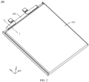
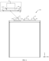
- FIG. 2 is a schematic diagram of a structure of the battery 400 in the electronic device 1000 shown in FIG. 1 .
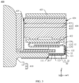
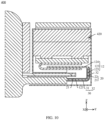
- FIG. 3 is a schematic diagram of a cross-sectional structure of the battery 400 shown in FIG. 2 after being sectioned along I-I.
- Being sectioned along I-I means being sectioned along a plane on which an I-I line is located, and the following related description may be understood in the same way.
- a length direction of the battery 400 is a Y-axis direction
- a width direction of the battery 400 is an X-axis direction
- a thickness direction of the battery 400 is a Z-axis direction.
- the battery 400 includes a battery cell assembly 410 and a protection board assembly 420.
- the protection board assembly 420 is mounted on a top side of the battery cell assembly 410 and is electrically connected to the battery cell assembly 410.
- the protection board assembly 420 includes a protection circuit board 421, an electrical connector 422, and an external circuit board 423.
- the electrical connector 422 is located on a lower side of the protection circuit board 421 and is electrically connected between the protection circuit board 421 and the battery cell assembly 410, to implement electrical connection between the protection board assembly 420 and the battery cell assembly 410.
- the electrical connector 422 may be in a "U" shape.
- the external circuit board 423 is located on an upper side of the protection circuit board 421 and is electrically connected to the protection circuit board 421 and the circuit board 300 (as shown in FIG. 1 ), to implement electrical connection between the protection board assembly 420 and the circuit board 300, and further implement electrical connection between the battery 400 and the circuit board 300.
- the protection circuit board 421 includes a first side surface 424 and a second side surface 425.
- the first side surface 424 is a surface that is of the protection circuit board 421 and that faces a positive direction of the Y axis
- the second side surface 425 is a surface that is of the protection circuit board 421 and that faces a negative direction of the Y axis.
- the first side surface 424 is arranged opposite to the second side surface 425 along the Y-axis direction.
- a length of the protection circuit board 421 is D.
- a distance between the first side surface 424 and the second side surface 425 along the Y-axis direction is D.
- D is less than or equal to 3.5 mm. In some other embodiments, D may alternatively be greater than 3.5 mm.
- the mentioned “length” means a dimension of a component along the Y-axis direction
- the mentioned “width” means a dimension of the component along the X-axis direction when a dimension of the component is described. The following related description may be understood in the same way.
- the battery cell assembly 410 includes a battery cell 10, a first tab glue 20, and a second tab glue 30.
- the battery cell 10 includes a battery cell body 11 and a tab 12.
- the tab 12 extends relative to the battery cell body 11.
- the battery cell body 11 has a reference surface 111, and the reference surface 111 is a surface that is of the battery cell body 11 and that faces the positive direction of the Y axis.
- the tab 12 extends relative to the reference surface 111.
- the tab 12 includes a first surface 121 and a second surface 122.
- the first surface 121 is arranged opposite to the second surface 122 along a thickness direction of the tab 12.
- the first surface 121 is a surface that is of the tab 12 and that faces the battery cell body 11
- the second surface 122 is a surface that is of the tab 12 and that is away from the battery cell body 11.
- the first tab glue 20 is provided on the first surface 121
- the second tab glue 30 is provided on the second surface 122.
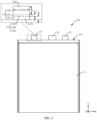
- FIG. 4 is a schematic diagram of a structure of the battery cell 10 of the battery cell assembly 410 in the battery 400 shown in FIG. 3 .
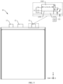
- FIG. 5 is a schematic diagram of a structure of the battery cell 10 shown in FIG. 4 from another perspective.
- the battery cell 10 shown in FIG. 4 and FIG. 5 is not been assembled with the protection board assembly 420, and the tab 12 of the battery cell 10 is in an unbent state. In other words, the tab 12 of the battery cell 10 is in a flattened state.
- a quantity of tabs 12 are three.
- the three tabs 12 all project relative to the reference surface 111 and are arranged at intervals from each other along the X-axis direction.
- One tab 12 is used as a positive tab of the battery cell 10
- one tab 12 is used as a negative tab of the battery cell 10
- one tab 12 is used as a reference tab of the battery cell 10.
- the reference tab is a tab in the battery cell 10 of which potential is always 0 V.
- the battery cell assembly 410 may include an electrode unit (not shown in the figure) and a packaging film (not shown in the figure).
- the packaging film covers an outer surface of the electrode unit to package the electrode unit.
- the electrode unit includes a plurality of positive electrode sheets, a plurality of negative electrode sheets, a plurality of reference electrode sheets, and a plurality of separators.
- the plurality of positive electrode sheets, the plurality of negative electrode sheets, and the plurality of reference electrode sheets are alternately stacked. Some of the separators are located between a positive electrode sheet and a negative electrode sheet, some of the separators are located between a positive electrode sheet and a reference electrode sheet, and some of the separators are located between a negative electrode sheet and a reference electrode sheet.
- Each positive electrode sheet includes a positive tab portion, and positive tab portions of the plurality of positive electrode sheets are electrically connected to form the positive tab.
- Each negative electrode sheet includes a negative tab portion, and negative tab portions of the plurality of negative electrode sheets are electrically connected to form the negative tab.
- Each reference electrode sheet includes a reference tab portion, and reference tab portions of the plurality of reference electrode sheets are electrically connected to form the reference tab.
- a quantity of the tabs 12 may alternatively be two.
- One is used as a positive tab of the battery cell 10, and the other is used as a negative tab of the battery cell 10.
- the electrode unit includes a plurality of positive electrode sheets, a plurality of negative electrode sheets, and a plurality of separators.
- the plurality of positive electrode sheets and the plurality of negative electrode sheets are alternately stacked.
- Each separator is located between a positive electrode sheet and a negative electrode sheet. Positive tab portions of the plurality of positive electrode sheets are electrically connected to form the positive tab, and negative tab portions of the plurality of negative electrode sheets are electrically connected to form the negative tab.
- Each tab 12 includes a fixed tab portion 123, an active tab portion 124, and a bent tab portion 125.
- the bent tab portion 125 is fastened between the fixed tab portion 123 and the active tab portion 124.
- Each tab 12 has a flattened state and a bent state. When the tab 12 is in a flattened state (as shown in FIG. 4 and FIG. 5 ), the bent tab portion 125 is in a flattened state, and the fixed tab portion 123 and the active tab portion 124, the fixed tab portion 123 and the bent tab portion 125, and the active tab portion 124 and the bent tab portion 125 are all relatively flattened.
- the bent tab portion 125 is in a bent state (as shown in FIG. 3 )
- the bent tab portion 125 is in a bent state
- the fixed tab portion 123 is spaced apart and arranged opposite to the active tab portion 124
- the bent tab portion 125 is bent relative to the fixed tab portion 123 and active tab portion 124.
- the fixed tab portion 123 is located on a side that is of the tab 12 and that is close to the battery cell body 11 and is fastened to the battery cell body 11.
- the fixed tab portion 123 includes an inner side surface 1231 and an outer side surface 1232.
- the inner side surface 1231 is arranged opposite to the outer side surface 1232 of the fixed tab portion 123 along a thickness direction (a Z-axis direction in the figure) of the fixed tab portion 123.
- a length of the fixed tab portion 123 is l 1
- a width of the fixed tab portion 123 is w 1 .
- l 1 may be 1.2 mm.
- the bent tab portion 125 is fastened between an end that is of the fixed tab portion 123 and that is away from the battery cell body 11 and an end that is of active tab portion 124 and that is close to the battery cell body 11.
- a length of the bent tab portion 125 is l 3
- a width of the bent tab portion 125 is w 3 .
- l 3 is less than l 1
- w 3 is equal to w 1 .
- l 1 may be 0.6 mm.
- l 3 may alternatively be greater than or equal to l 1
- w 3 may alternatively be less than or equal to w 0 .
- the bent tab portion 125 includes an inner side surface 1251 and an outer side surface 1252.
- the inner side surface 1251 is arranged opposite to the outer side surface 1252 of the bent tab portion 125 along a thickness direction (the Z-axis direction in the figure) of the bent tab portion 125.
- the inner side surface 1251 of the bent tab portion 125 is fastened between the inner side surface 1231 of the fixed tab portion 123 and the inner side surface 1241 of the active tab portion 124.
- the outer side surface 1252 of the bent tab portion 125 is fastened between the outer side surface 1232 of the fixed tab portion 123 and the outer side surface 1242 of the active tab portion 124.
- the first surface 121 includes the inner side surface 1231 of the fixed tab portion 123, the inner side surface 1241 of the active tab portion 124, and the inner side surface 1251 of the bent tab portion 125.
- the second surface 122 includes the outer side surface 1232 of the fixed tab portion 123, the outer side surface 1242 of the active tab portion 124, and the outer side surface 1252 of the bent tab portion 125.
- the tab 12 When the tab 12 is in a bent state, the tab 12 is bent from the second surface 122 to the first surface 121.
- the bent tab portion 125 is bent relative to the fixed tab portion 123 and the active tab portion 124.
- the active tab portion 124 is located on an upper side of the fixed tab portion 123 and is arranged opposite to the fixed tab portion 123.
- the active tab portion 124 may extend into an opening of the electrical connector 422 and be electrically connected to the electrical connector 422 to implement electrical connection between the tab 12 and the electrical connector 422, thereby implementing electrical connection between the battery cell 10 and the electrical connector 422, and further implementing electrical connection between the battery cell assembly 410 and the electrical connector 422.
- FIG. 6 is a schematic diagram of a structure of the battery cell assembly 410 in the battery 400 shown in FIG. 3 in a first implementation.
- FIG. 7 is a schematic diagram of a structure of the battery cell assembly 410 shown in FIG. 6 from another perspective.
- the battery cell assembly 410 shown in FIG. 6 and FIG. 7 is not assembled with the protection board assembly 420. In this case, in the battery cell assembly 410, the tab 12 of the battery cell 10, the first tab glue 20, and the second tab glue 30 are in an unbent state.
- both a quantity of first tab glues 20 and a quantity of second tab glues 30 are three.
- the three first tab glues 20 are respectively provided on first surfaces 121 of three tabs 12.
- the three second tab glues 30 are respectively provided on second surfaces 122 of the three tabs 12. It may be understood that the quantity of the first tab glues 20 and the quantity of the second tab glues 30 should match a quantity of tabs 12.
- both the quantity of the first tab glues 20 and the quantity of the second tab glues 30 are two.
- the two first tab glues 20 are respectively provided on the first surfaces 121 of the two tabs 12, and the two second tab glues 30 are respectively provided on the second surfaces 122 of the two tabs 12.
- structures of the first tab glues 20 are the same.
- a matching relationship between each of the first tab glues 20 and a tab 12 is the same.
- Structures of the second tab glues 30 are the same.
- a matching relationship between each of the second tab glues 30 and a tab 12 are the same.
- a matching relationship between each of the second tab glues 30 and a first tab glue 20 are the same.
- the following uses a tab 12, a first tab glue 20, and a second tab glue 30 as an example to describe the structure of the battery cell assembly 410 in detail.
- the first tab glue 20 is provided on the inner side surface 1231 of the fixed tab portion 123, and covers the inner side surface 1231 of the fixed tab portion 123. In this case, the inner side surface 1251 of the bent tab portion 125 is exposed relative to the first tab glue 20. In other words, the first tab glue 20 is not provided on the inner side surface 1251 of the bent tab portion 125. In other words, a tab glue is not provided on the inner side surface 1251 of the bent tab portion 125.
- the first tab glue 20 is in a "straight-line" shape.
- a length of the first tab glue 20 is L 1 , and L 1 is equal to l 1 .
- L 1 may be 1.2 mm.
- L 1 may alternatively be less than l 1 .
- the length L 1 of the first tab glue 20 may be less than or equal to the length l 1 of the fixed tab portion 123.
- a width of the first tab glue 20 is W 1 , and W 1 is greater than w 1 .
- a left side surface (not marked in the figure) of the first tab glue 20 projects relative to a left side surface (not marked in the figure) of the fixed tab portion 123, and a right side surface (not marked in the figure) of the first tab glue 20 projects relative to a right side surface (not marked in the figure) of the fixed tab portion 123.
- the left side surface of the first tab glue 20 may alternatively not project relative to the left side surface of the fixed tab portion 123, or the right side surface of the first tab glue 20 may not project relative to the right side surface of the fixed tab portion 123, or W 1 may be less than or equal to w 1 .
- the second tab glue 30 is provided on the outer side surface 1232 of the fixed tab portion 123 and the outer side surface 1242 of the bent tab portion 125, and covers the outer side surface 1232 of the fixed tab portion 123 and the outer side surface 1242 of the bent tab portion 125.
- the second tab glue 30 is in an inverted "T" shape.
- the second tab glue 30 includes a first glue portion 31 and a second glue portion 32.
- the second glue portion 32 is located on a top side of the first glue portion 31 and is fastened to the first glue portion 31.
- the first glue portion 31 is provided on the outer side surface 1232 of the fixed tab portion 123, and covers the outer side surface 1232 of the fixed tab portion 123.
- the first glue portion 31 is in a "straight-line" shape.
- a length of the first glue portion 31 is L 2 , and L 2 is equal to l 1 .
- L 2 is equal to L 1 .
- L 2 may be 1.2 mm.
- L 2 may alternatively be less than l 1 .
- the length L 2 of the first glue portion 31 is less than or equal to the length l 1 of the fixed tab portion 123.
- a width of the first glue portion 31 is W 2 , and W 2 is greater than w 1 and equal to W 1 .
- a left side surface (not marked in the figure) of the first glue portion 31 projects relative to the left side surface (not marked in the figure) of the fixed tab portion 123, and a right side surface (not marked in the figure) of the first glue portion 31 projects relative to the right side surface (not marked in the figure) of the fixed tab portion 123.
- the left side surface of the first glue portion 31 may be flush with the left side surface of the first tab glue
- the right side surface of the first glue portion 31 may be flush with the right side surface of the first tab glue 20.
- the left side surface of the first glue portion 31 may alternatively not project relative to the left side surface of the fixed tab portion 123, or the right side surface of the first glue portion 31 may not project relative to the right side surface of the fixed tab portion 123, or W 2 may be less than or equal to w 1 .
- the second glue portion 32 is provided on the outer side surface 1252 of the bent tab portion 125, and covers the outer side surface 1252 of the bent tab portion 125.
- a length of the second glue portion 32 is L 3 , and L 3 is equal to l 3 .
- L 3 may be 0.6 mm.
- L 3 may alternatively be less than l 1 .
- the length L 3 of the second glue portion 32 is less than or equal to the length l 3 of the bent tab portion 125.
- a width of the second glue portion 32 is W 3 , and W 3 is less than W 2 and equal to w 3 .
- a left side surface (not marked in the figure) of the second glue portion 32 is retracted relative to the left side surface of the first glue portion 31 and is flush with the left side surface (not marked in the figure) of the bent tab portion 125.
- a right side surface (not marked in the figure) of the second glue portion 32 is retracted relative to the right side surface of the first glue portion 31 and is flush with the right side surface (not marked in the figure) of the bent tab portion 125.
- the left side surface of the second glue portion 32 may alternatively project relative to the left side surface of the bent tab portion 125 and the right side surface of the second glue portion 32 is retracted relative to the right side surface of the bent tab portion 125, or the left side surface of the second glue portion 32 may be retracted relative to the left side surface of the bent tab portion 125 and the right side surface of the second glue portion 32 projects relative to the right side surface of the bent tab portion 125, or W 3 may be greater than or equal to w 3 .
- a qualifier such as "flush” and another relative positional relationship in embodiments of this application are all for the current process level, but not for absolute strict definitions in a mathematical sense. A small amount of deviation is allowed, and “approximately flush” is also acceptable.
- that the left side surface of the second glue portion 32 is flush with the left side surface of the bent tab portion 125 means that the left side surface of the second glue portion 32 is flush with or approximately flush with the left side surface of the bent tab portion 125.
- the left side surface of the second glue portion 32 may slightly project relative to the left side surface of the bent tab portion 125, or the left side surface of the second glue portion 32 may be slightly retracted relative to the left side surface of the bent tab portion 125.
- FIG. 8 is a schematic diagram of a structure of the battery cell assembly 410 in the battery 400 shown in FIG. 3 in a second implementation.
- FIG. 9 is a schematic diagram of a structure of the battery cell assembly 410 shown in FIG. 8 from another perspective.
- the battery cell assembly 410 shown in FIG. 8 and FIG. 9 is not assembled with the protection board assembly 420. In this case, in the battery cell assembly 410, the tab 12 of the battery cell 10, the first tab glue 20, and the second tab glue 30 are in an unbent state.
- the battery cell assembly 410 shown in this implementation is different from the battery cell assembly 410 shown in the foregoing implementation in that the first tab glue 20 is in an inverted "T" shape.
- the first tab glue 20 includes a first portion 21 and a second portion 22.
- the second portion 22 is located on a top side of the first portion 21 and is fastened to the first portion 21.
- a length of the first portion 21 is L 4 , and L 4 is less than to l 1 .
- L 4 may be 0.6 mm.
- a width of the first portion 21 is W 4 , and W 4 is greater than w 1 .
- a left side surface (not marked in the figure) of the first portion 21 projects relative to a left side surface (not marked in the figure) of the fixed tab portion 123, and a right side surface (not marked in the figure) of the first portion 21 projects relative to a right side surface (not marked in the figure) of the fixed tab portion 123.
- the left side surface of the first portion 21 may alternatively not project relative to the left side surface of the fixed tab portion 123, or the right side surface of the first portion 21 may not project relative to the right side surface of the fixed tab portion 123, or W 4 may be less than or equal to w 1 .
- a length of the second portion 22 is L 5 , L 5 is less than l 1 , and a sum of L 5 and L 4 is equal to l 1 .
- L 5 may be 0.4 mm, or L 5 may be 0.6 mm. In some other implementations, the sum of L 5 and L 4 may be less than l 1 .
- a width of the second portion 22 is W 5 , and W 5 is less than W 4 and equal to w 1 .
- a left side surface (not marked in the figure) of the second portion 22 is retracted relative to the left side surface of the first portion 21 and is flush with the left side surface of the fixed tab portion 123.
- a right side surface (not marked in the figure) of the second portion 22 is retracted relative to the right side surface of the first portion 21 and is flush with the right side surface of the fixed tab portion 123.
- the left side surface of the second portion 22 may alternatively project relative to the left side surface of the fixed tab portion 123 and the right side surface of the second portion 22 is retracted relative to the right side surface of the fixed tab portion 123, or the left side surface of the second portion 22 may be retracted relative to the left side surface of the fixed tab portion 123 and the right side surface of the second portion 22 projects relative to the right side surface of the fixed tab portion 123, or W 5 may be less than or greater than w 1 .
- a first glue portion 31 of the second tab glue 30 is in an inverted "T" shape.
- the first glue portion 31 includes a first sub-glue portion 311 and a second sub-glue portion 312.
- the second sub-glue portion 312 is located on a top side of the first sub-glue portion 311 and is fastened to the first sub-glue portion 311.
- a length of the first sub-glue portion 311 is L 6 , and L 6 is less than l 1 .
- L 6 may be 0.6 mm.
- a width of the first sub-glue portion 311 is W 6 , and W 6 is greater than w 1 .
- a left side surface (not marked in the figure) of the first sub-glue portion 311 projects relative to the left side surface (not marked in the figure) of the fixed tab portion 123, and a right side surface (not marked in the figure) of the first sub-glue portion 311 projects relative to the right side surface (not marked in the figure) of the fixed tab portion 123.
- the left side surface of the first sub-glue portion 311 may alternatively not project relative to the left side surface of the fixed tab portion 123, or the right side surface of the first sub-glue portion 311 may not project relative to the right side surface of the fixed tab portion 123, or W 6 may be less than or equal to w 1 .
- a length of the second sub-glue portion 312 is L 7 , L 7 is less than l 1 . and a sum of L 7 and L 6 is equal to l 1 .
- L 7 may be 0.6 mm. In some other implementations, the sum of L 7 and L 6 may be less than l 1 .
- a width of the second sub-glue portion 312 is W 7 , and W 7 is less than W 6 and equal to w 1 .
- a left side surface (not marked in the figure) of the second sub-glue portion 312 is retracted relative to the left side surface of the first sub-glue portion 311 and is flush with the left side surface of the fixed tab portion 123.
- a right side surface (not marked in the figure) of the second sub-glue portion 312 is retracted relative to the right side surface of the first sub-glue portion 311 and is flush with the right side surface of the fixed tab portion 123.
- the left side surface of the second sub-glue portion 312 may alternatively project relative to the left side surface of the fixed tab portion 123 and the right side surface of the second sub-glue portion 312 is retracted relative to the right side surface of the fixed tab portion 123, or the left side surface of the second sub-glue portion 312 may be retracted relative to the left side surface of the fixed tab portion 123 and the right side surface of the second sub-glue portion 312 projects relative to the right side surface of the fixed tab portion 123, or W 7 may be less than or greater than w 1 .
- the bent tab portion 125 of the tab 12 needs to be bent relative to the fixed tab portion 123 and the active tab portion 124, to be electrically connected to the protection board assembly 420. Because there is no tab glue on the inner side surface 1251 of the bent tab portion 125 in the tab 12, it is not only convenient to bend the bent tab portion 125 of the tab 12, to facilitate improvement of assembly convenience of the battery 400, but also can reduce space occupation of the tab glue on the surface of the bent tab portion 125 in the length direction of the battery 400, thereby avoiding space waste of the battery 400 in the length direction and facilitating improvement of a capacity of the battery 400.
- the second glue portion 32 is located between the first side surface 424 and the second side surface 425 of the protection circuit board 421. In other words, the second glue portion 32 does not project relative to the first side surface 424 of the protection circuit board 421, to ensure that a length of the battery cell assembly 410 satisfies a packaging specification of the protection circuit board 421 after the battery 400 is packaged.
- the second tab glue 30 completely covers the outer side surface 1232 of the fixed tab portion 123 and the outer side surface 1252 of the bent tab portion 125. This can effectively protect an exposed portion of the tab 12, thereby preventing the tab 12 from contacting another component to cause a short circuit, and ensuring usage reliability of the battery 400.
- the second tab glue 30 may alternatively be provided on the outer side surface 1232 of the fixed tab portion 123, and covers the outer side surface 1232 of the fixed tab portion 123. In this case, the outer side surface 1252 of the bent tab portion 125 is exposed relative to the second tab glue 30. In other words, the second tab glue 30 is not provided on the outer side surface 1252 of the bent tab portion 125.
- a tab glue is not provided on the outer side surface 1252 of the bent tab portion 125.
- the second tab glue 30 may alternatively only include the first glue portion 31 in the foregoing implementation. This can not only further facilitate bending of the bent tab portion 125 of the tab 12, but also further reduce space occupation of the second tab glue 30 in the length direction of the battery 400, and further improve a capacity of the battery 400.
- FIG. 10 is a schematic diagram of a cross-sectional structure of a battery 400 in a second electronic device after being sectioned along I-I according to an embodiment of this application.
- FIG. 11 is a schematic diagram of a structure of a battery cell assembly 410 in the battery 400 shown in FIG. 10 in a first implementation.
- the battery cell assembly 410 shown in FIG. 11 is not assembled with a protection board assembly 420.
- a tab 12 of a battery cell 10 a first tab glue 20, and a second tab glue 30 are in an unbent state.
- the battery 400 shown in this embodiment is different from the battery 400 shown in the foregoing embodiment in that the first tab glue 20 covers an inner side surface 1231 of a fixed tab portion 123 and an inner side surface 1251 of a bent tab portion 125, and covers the inner side surface 1231 of the fixed tab portion 123 and the inner side surface 1251 of the bent tab portion 125.
- the second tab glue 30 and a matching relationship between the second tab glue 30 and the tab 12 refer to relevant descriptions of the second tab glue 30 shown in the second implementation of the first embodiment. This is not described again herein.
- the first tab glue 20 is in an inverted "T" shape.
- the first tab glue 20 includes a first portion 21 and a second portion 22.
- the second portion 22 is located on a top side of the first portion 21 and is fastened to the first portion 21.
- the first portion 21 is provided on the inner side surface 1231 of the fixed tab portion 123, and covers the inner side surface 1231 of the fixed tab portion 123.
- the first portion 21 is in an inverted "T" shape.
- the first portion 21 includes a first sub-portion 211 and a second sub-portion 212.
- the second sub-portion 212 is located on a top side of the first sub-portion 211 and is fastened between the first sub-portion 211 and the second portion 22.
- a length of the first sub-portion 211 is L 8 , and L 8 is less than l 1 .
- L 8 may be 0.6 mm.
- a width of the first sub-portion 211 is W 8 , and W 8 is greater than w 1 .
- a left side surface (not marked in the figure) of the first sub-portion 211 projects relative to a left side surface (not marked in the figure) of the fixed tab portion 123, and a right side surface (not marked in the figure) of the first sub-portion 211 projects relative to a right side surface (not marked in the figure) of the fixed tab portion 123.
- the left side surface of the first sub-portion 211 may alternatively not project relative to the left side surface of the fixed tab portion 123, or the right side surface of the first sub-portion 211 may not project relative to the right side surface of the fixed tab portion 123, or W 8 may be less than or equal to W 1 .
- a length of the second sub-portion 212 is L 9 , L 9 is less than l 1 , and a sum of L 9 and L 8 is equal to l 1 .
- L 9 may be 0.6 mm. In some other implementations, the sum of L 9 and L 8 may be less than l 1 .
- a width of the second sub-portion 212 is W 9 , and W 9 is less than W8 and equal to w 1 .
- a left side surface (not marked in the figure) of the second sub-portion 212 is retracted relative to the left side surface of the first sub-portion 211 and is flush with the left side surface of the fixed tab portion 123.
- a right side surface (not marked in the figure) of the second sub-portion 212 is retracted relative to the right side surface of the first sub-portion 211 and is flush with the right side surface of the fixed tab portion 123.
- the left side surface of the second sub-portion 212 may alternatively project relative to the left side surface of the fixed tab portion 123 and the right side surface of the second sub-portion 212 is retracted relative to the right side surface of the fixed tab portion 123, or the left side surface of the second sub-portion 212 may be retracted relative to the left side surface of the fixed tab portion 123 and the right side surface of the second sub-portion 212 projects relative to the right side surface of the fixed tab portion 123, or W 9 may be less than or greater than w 1 .
- the second portion 22 is fastened to an end that is of the second sub-portion 212 and that is away from the first sub-portion 211. Specifically, the second portion 22 is provided on the inner side surface 1251 of the bent tab portion 125, and covers the inner side surface of the bent tab portion 125. In this implementation, the second portion 22 is in a "straight-line" shape.
- a length of the second portion 22 is L 10 , and L 10 is equal to l 10 .
- L 10 may be 0.6 mm.
- L 10 may alternatively be less than l 1 .
- the length L 10 of the second portion 22 is less than or equal to the length l 10 of the bent tab portion 125.
- a width of the second portion 22 is W 10 , and W 10 is less than W 8 and equal to W 8 and w 3 .
- a left side surface (not marked in the figure) of the second portion 22 is retracted relative to the left side surface of the first sub-portion 211 and is flush with the left side surface of the second sub-portion 212 and the left side surface (not marked in the figure) of the bent tab portion 125.
- a right side surface (not marked in the figure) of the second portion 22 is retracted relative to the right side surface of the first sub-portion 211 and is flush with the right side surface of the second sub-portion 212 and the right side surface (not marked in the figure) of the bent tab portion 125.
- the left side surface of the second portion 22 may alternatively be retracted relative to the left side surface of the bent tab portion 125, or the right side surface of the second portion art 22 is retracted relative to the right side surface of the bent tab portion 125, or W 10 may be greater than or equal to w 3 .
- the bent tab portion 125 of the tab 12 needs to be bent relative to the fixed tab portion 123 and the active tab portion 124 to be electrically connected to the protection board assembly 420. Because the second portion 22 in the first tab glue 20 and the second glue portion 32 in the second tab glue 30 does not project relative to the left side surface and the right side surface of the bent tab portion 125, when the bent tab portion 125 is bent relative to the fixed tab portion 123 and the active tab portion 124, both the second portion 22 and the second glue portion 32 are bent along with the bent tab portion 125.
- the first tab glue 20 completely covers the inner side surface 1231 of the fixed tab portion 123 and the inner side surface of the bent tab portion 125.
- the second tab glue 30 completely covers the outer side surface 1232 of the fixed tab portion 123 and the outer side surface 1252 of the bent tab portion 125. This can effectively protect the fixed tab portion 123 and the bent tab portion 125 in the tab 12, thereby preventing the tab 12 from contacting another component to cause a short circuit, and ensuring effective use of the battery 400.
- FIG. 12 is a schematic diagram of a structure of the battery cell assembly 410 in the battery 400 shown in FIG. 10 in a second implementation.
- the battery cell assembly 410 shown in FIG. 12 is not assembled with the protection board assembly 420.
- the tab 12 of the battery cell 10 the first tab glue 20, and the second tab glue 30 are in an unbent state.
- the battery cell assembly 410 shown in this implementation is different from the battery cell assembly 410 shown in the first implementation in that the first tab glue 20 and the second tab glue 30 are both trapezoidal.
- the first tab glue 20 and the second tab glue 30 are both trapezoidal.
- Widths of the first portion 21 and the second portion 22 gradually increase along a direction (a negative direction of a Y axis in the figure) of the second portion 22 toward the first portion 21.
- a minimum width of the first portion 21 is W 11 , and W 11 is greater than w 1 .
- a left side surface (not marked in the figure) of the first portion 21 projects relative to a left side surface of the fixed tab portion 123, and a right side surface (not marked in the figure) of the first portion 21 projects relative to a right side surface of the fixed tab portion 123.
- An included angle between the left side surface of the first portion 21 and the left side surface of the fixed tab portion 123 is ⁇ 1 .
- An included angle between the right side surface of the first portion 21 and the right side surface of the fixed tab portion 123 is ⁇ 2 . Both ⁇ 1 and ⁇ 2 are acute angles. For example, ⁇ 1 is equal to ⁇ 2 .
- a minimum width of the second portion 22 is W 12 , and W 12 is less than W 11 and equal to w 1 .
- a maximum width of the second portion 22 is W 13 , and W 13 is greater than W 12 and equal to W 11 .
- a left side surface (not marked in the figure) of the second portion 22 projects relative to a left side surface of the bent tab portion 125, and is flush with the left side surface of the first portion 21.
- a right side surface (not marked in the figure) of the second portion 22 projects relative to a right side surface of the bent tab portion 125, and is flush with the right side surface of the first portion 21. Specifically, an end that is of the left side surface of the second portion 22 and that is away from the first portion 21 is connected to the left side surface of the bent tab portion 125.
- An end that is of the left side surface of the second portion 22 and that is close to the first portion 21 is connected to the left side surface of the first portion 21.
- An end that is of the right side surface of the second portion 22 and that is away from the first portion 21 is connected to the right side surface of the bent tab portion 125.
- An end that is of the right side surface of the second portion 22 and that is close to the first portion 21 is connected to the right side surface of the first portion 21.
- An included angle between the left side surface of the second portion 22 and the left side surface of the bent tab portion 125 is ⁇ 3 .
- An included angle between the right side surface of the second portion 22 and the right side surface of the bent tab portion 125 is ⁇ 4 . Both ⁇ 3 and ⁇ 4 are acute angles. For example, ⁇ 3 is equal to ⁇ 1 , and ⁇ 4 is equal to ⁇ 2 .
- the bent tab portion 125 of the tab 12 needs to be bent relative to the fixed tab portion 123 and the active tab portion 124, to be electrically connected to the protection board assembly 420. Because the second portion 22 in the first tab glue 20 and the second glue portion 32 in the second tab glue 30 project less relative to the left side surface and the right side surface of the bent tab portion 125, when the bent tab portion 125 is bent relative to the fixed tab portion 123 and the active tab portion 124, both the second portion 22 and the second glue portion 32 are bent along with the bent tab portion 125.
Landscapes
- Chemical & Material Sciences (AREA)
- Chemical Kinetics & Catalysis (AREA)
- Electrochemistry (AREA)
- General Chemical & Material Sciences (AREA)
- Engineering & Computer Science (AREA)
- Microelectronics & Electronic Packaging (AREA)
- Manufacturing & Machinery (AREA)
- Connection Of Batteries Or Terminals (AREA)
- Battery Mounting, Suspending (AREA)
Applications Claiming Priority (2)
| Application Number | Priority Date | Filing Date | Title |
|---|---|---|---|
| CN202310093647.2A CN118431690B (zh) | 2023-01-31 | 2023-01-31 | 电芯组件、电池和电子设备 |
| PCT/CN2023/136380 WO2024159910A1 (zh) | 2023-01-31 | 2023-12-05 | 电芯组件、电池和电子设备 |
Publications (2)
| Publication Number | Publication Date |
|---|---|
| EP4564585A1 true EP4564585A1 (de) | 2025-06-04 |
| EP4564585A4 EP4564585A4 (de) | 2026-02-25 |
Family
ID=92024346
Family Applications (1)
| Application Number | Title | Priority Date | Filing Date |
|---|---|---|---|
| EP23919474.9A Pending EP4564585A4 (de) | 2023-01-31 | 2023-12-05 | Batteriezellenanordnung, batterie und elektronische vorrichtung |
Country Status (4)
| Country | Link |
|---|---|
| US (1) | US20260081322A1 (de) |
| EP (1) | EP4564585A4 (de) |
| CN (2) | CN118431690B (de) |
| WO (1) | WO2024159910A1 (de) |
Family Cites Families (11)
| Publication number | Priority date | Publication date | Assignee | Title |
|---|---|---|---|---|
| CN101276931A (zh) * | 2007-03-30 | 2008-10-01 | 深圳市邦凯电子有限公司 | 软包装锂电池及其加工方法 |
| CN201904407U (zh) * | 2010-12-17 | 2011-07-20 | 天津力神电池股份有限公司 | 一种高比容量聚合物锂离子电池 |
| WO2021249341A1 (zh) * | 2020-06-08 | 2021-12-16 | 华为技术有限公司 | 一种锂离子电池及包括锂离子电池的终端设备 |
| CN212783615U (zh) * | 2020-09-09 | 2021-03-23 | 微宏动力系统(湖州)有限公司 | 用于电池的极耳及电池 |
| CN213150965U (zh) * | 2020-09-11 | 2021-05-07 | 东莞新能德科技有限公司 | 电池和使用电池的装置 |
| CN112467261B (zh) * | 2020-11-24 | 2023-03-28 | 东莞新能德科技有限公司 | 电池和使用电池的装置 |
| CN113611986B (zh) * | 2021-07-30 | 2022-12-27 | 东莞新能德科技有限公司 | 电芯、电池及电子设备 |
| CN113871805A (zh) * | 2021-09-02 | 2021-12-31 | 东莞新能德科技有限公司 | 电芯、电池、电芯的制造方法及电子设备 |
| CN216563449U (zh) * | 2021-12-24 | 2022-05-17 | 珠海冠宇电池股份有限公司 | 电芯和电池 |
| CN114335676B (zh) * | 2022-02-10 | 2025-01-28 | 珠海冠宇电源有限公司 | 电池 |
| CN217468608U (zh) * | 2022-06-08 | 2022-09-20 | 珠海冠宇电池股份有限公司 | 电池 |
-
2023
- 2023-01-31 CN CN202310093647.2A patent/CN118431690B/zh active Active
- 2023-12-05 WO PCT/CN2023/136380 patent/WO2024159910A1/zh not_active Ceased
- 2023-12-05 CN CN202380091545.5A patent/CN120604393A/zh active Pending
- 2023-12-05 US US19/108,066 patent/US20260081322A1/en active Pending
- 2023-12-05 EP EP23919474.9A patent/EP4564585A4/de active Pending
Also Published As
| Publication number | Publication date |
|---|---|
| WO2024159910A1 (zh) | 2024-08-08 |
| CN120604393A (zh) | 2025-09-05 |
| CN118431690A (zh) | 2024-08-02 |
| CN118431690B (zh) | 2025-09-26 |
| EP4564585A4 (de) | 2026-02-25 |
| US20260081322A1 (en) | 2026-03-19 |
Similar Documents
| Publication | Publication Date | Title |
|---|---|---|
| WO2020259322A1 (zh) | 电子设备 | |
| US11729302B2 (en) | Battery having electrode tabs and electronic device having same | |
| KR102582586B1 (ko) | 무지부의 적어도 일부에 노치가 형성된 배터리를 포함하는 전자 장치 | |
| CN115175454B (zh) | 一种电子设备 | |
| CN212011033U (zh) | 电池及具有所述电池的电子装置 | |
| US20250266488A1 (en) | Battery and electronic apparatus | |
| US20250046966A1 (en) | Battery and electronic device | |
| CN205071069U (zh) | 移动终端 | |
| EP4564585A1 (de) | Batteriezellenanordnung, batterie und elektronische vorrichtung | |
| US20250038322A1 (en) | Electrochemical device, battery module, and electronic device | |
| CN217217080U (zh) | 电子组件及电子设备 | |
| CN114361559A (zh) | 电池 | |
| US20210104712A1 (en) | Battery pack and electronic apparatus | |
| JP2019075358A (ja) | ラミネート型電池 | |
| KR101502899B1 (ko) | 전지 팩 | |
| JP2007065855A (ja) | タッチパネル付き表示装置 | |
| CN217467411U (zh) | 显示面板及显示设备 | |
| CN116256915A (zh) | 显示模组和显示装置 | |
| US12147622B2 (en) | Display device | |
| CN115954588A (zh) | 包装袋、电化学装置及电子设备 | |
| CN112578860A (zh) | 一种电子设备 | |
| CN209843753U (zh) | 层叠型电池 | |
| CN224190989U (zh) | 电化学装置以及用电设备 | |
| CN106982524A (zh) | 显示组件及移动终端 | |
| CN222838931U (zh) | 电池胶框及电池组件 |
Legal Events
| Date | Code | Title | Description |
|---|---|---|---|
| STAA | Information on the status of an ep patent application or granted ep patent |
Free format text: STATUS: THE INTERNATIONAL PUBLICATION HAS BEEN MADE |
|
| PUAI | Public reference made under article 153(3) epc to a published international application that has entered the european phase |
Free format text: ORIGINAL CODE: 0009012 |
|
| STAA | Information on the status of an ep patent application or granted ep patent |
Free format text: STATUS: REQUEST FOR EXAMINATION WAS MADE |
|
| 17P | Request for examination filed |
Effective date: 20250228 |
|
| AK | Designated contracting states |
Kind code of ref document: A1 Designated state(s): AL AT BE BG CH CY CZ DE DK EE ES FI FR GB GR HR HU IE IS IT LI LT LU LV MC ME MK MT NL NO PL PT RO RS SE SI SK SM TR |
|
| A4 | Supplementary search report drawn up and despatched |
Effective date: 20260122 |
|
| RIC1 | Information provided on ipc code assigned before grant |
Ipc: H01M 50/533 20210101AFI20260116BHEP Ipc: H01M 50/557 20210101ALI20260116BHEP Ipc: H01M 50/562 20210101ALI20260116BHEP Ipc: H01M 50/588 20210101ALI20260116BHEP Ipc: H01M 50/59 20210101ALI20260116BHEP Ipc: H01M 10/42 20060101ALI20260116BHEP |