EP4564628A1 - Système de protection pour système cc bipolaire terra isolé - Google Patents
Système de protection pour système cc bipolaire terra isolé Download PDFInfo
- Publication number
- EP4564628A1 EP4564628A1 EP23213501.2A EP23213501A EP4564628A1 EP 4564628 A1 EP4564628 A1 EP 4564628A1 EP 23213501 A EP23213501 A EP 23213501A EP 4564628 A1 EP4564628 A1 EP 4564628A1
- Authority
- EP
- European Patent Office
- Prior art keywords
- current
- fault
- conductor
- midpoint
- predetermined
- Prior art date
- Legal status (The legal status is an assumption and is not a legal conclusion. Google has not performed a legal analysis and makes no representation as to the accuracy of the status listed.)
- Pending
Links
Images




Classifications
-
- H—ELECTRICITY
- H02—GENERATION; CONVERSION OR DISTRIBUTION OF ELECTRIC POWER
- H02H—EMERGENCY PROTECTIVE CIRCUIT ARRANGEMENTS
- H02H3/00—Emergency protective circuit arrangements for automatic disconnection directly responsive to an undesired change from normal electric working condition with or without subsequent reconnection ; integrated protection
- H02H3/16—Emergency protective circuit arrangements for automatic disconnection directly responsive to an undesired change from normal electric working condition with or without subsequent reconnection ; integrated protection responsive to fault current to earth, frame or mass
-
- B—PERFORMING OPERATIONS; TRANSPORTING
- B60—VEHICLES IN GENERAL
- B60L—PROPULSION OF ELECTRICALLY-PROPELLED VEHICLES; SUPPLYING ELECTRIC POWER FOR AUXILIARY EQUIPMENT OF ELECTRICALLY-PROPELLED VEHICLES; ELECTRODYNAMIC BRAKE SYSTEMS FOR VEHICLES IN GENERAL; MAGNETIC SUSPENSION OR LEVITATION FOR VEHICLES; MONITORING OPERATING VARIABLES OF ELECTRICALLY-PROPELLED VEHICLES; ELECTRIC SAFETY DEVICES FOR ELECTRICALLY-PROPELLED VEHICLES
- B60L3/00—Electric devices on electrically-propelled vehicles for safety purposes; Monitoring operating variables, e.g. speed, deceleration or energy consumption
- B60L3/0023—Detecting, eliminating, remedying or compensating for drive train abnormalities, e.g. failures within the drive train
- B60L3/0069—Detecting, eliminating, remedying or compensating for drive train abnormalities, e.g. failures within the drive train relating to the isolation, e.g. ground fault or leak current
-
- B—PERFORMING OPERATIONS; TRANSPORTING
- B60—VEHICLES IN GENERAL
- B60L—PROPULSION OF ELECTRICALLY-PROPELLED VEHICLES; SUPPLYING ELECTRIC POWER FOR AUXILIARY EQUIPMENT OF ELECTRICALLY-PROPELLED VEHICLES; ELECTRODYNAMIC BRAKE SYSTEMS FOR VEHICLES IN GENERAL; MAGNETIC SUSPENSION OR LEVITATION FOR VEHICLES; MONITORING OPERATING VARIABLES OF ELECTRICALLY-PROPELLED VEHICLES; ELECTRIC SAFETY DEVICES FOR ELECTRICALLY-PROPELLED VEHICLES
- B60L53/00—Methods of charging batteries, specially adapted for electric vehicles; Charging stations or on-board charging equipment therefor; Exchange of energy storage elements in electric vehicles
- B60L53/10—Methods of charging batteries, specially adapted for electric vehicles; Charging stations or on-board charging equipment therefor; Exchange of energy storage elements in electric vehicles characterised by the energy transfer between the charging station and the vehicle
- B60L53/11—DC charging controlled by the charging station, e.g. mode 4
-
- G—PHYSICS
- G01—MEASURING; TESTING
- G01R—MEASURING ELECTRIC VARIABLES; MEASURING MAGNETIC VARIABLES
- G01R31/00—Arrangements for testing electric properties; Arrangements for locating electric faults; Arrangements for electrical testing characterised by what is being tested not provided for elsewhere
- G01R31/50—Testing of electric apparatus, lines, cables or components for short-circuits, continuity, leakage current or incorrect line connections
- G01R31/52—Testing for short-circuits, leakage current or ground faults
-
- H—ELECTRICITY
- H02—GENERATION; CONVERSION OR DISTRIBUTION OF ELECTRIC POWER
- H02H—EMERGENCY PROTECTIVE CIRCUIT ARRANGEMENTS
- H02H3/00—Emergency protective circuit arrangements for automatic disconnection directly responsive to an undesired change from normal electric working condition with or without subsequent reconnection ; integrated protection
- H02H3/02—Details
- H02H3/04—Details with warning or supervision in addition to disconnection, e.g. for indicating that protective apparatus has functioned
- H02H3/042—Details with warning or supervision in addition to disconnection, e.g. for indicating that protective apparatus has functioned combined with means for locating the fault
Definitions
- the invention relates to a protection system and method for a DC system, wherein the DC system is an isolated terra bipolar DC system comprising a positive conductor, a negative conductor, and a midpoint conductor, wherein the DC system is designed to be symmetric around a midpoint at the midpoint conductor.
- DC section A critical requirement across these applications is the necessity for the DC section to be an Isolated Terra (IT) circuit. This configuration is essential for human protection and permits the occurrence of a single fault without destructive outcomes.
- IT Isolated Terra
- DC systems present significant protection challenges.
- One potential solution for increasing the DC system's voltage is the adoption of a symmetric, bipolar configuration.
- IMDs Insulation Monitoring Devices
- MCS Megawatt Charging Standard
- IT-circuit-based systems examples include bipolar and unipolar DC systems (such as HVDC infrastructure or LVDC equivalent and chargers or PV installations, respectively), and split-phase electric power AC systems (like the 240 V AC system with two 120 V AC phases in anti-phase, commonly used in the USA).
- bipolar and unipolar DC systems such as HVDC infrastructure or LVDC equivalent and chargers or PV installations, respectively
- split-phase electric power AC systems like the 240 V AC system with two 120 V AC phases in anti-phase, commonly used in the USA.
- a protection system for a DC system, wherein the DC system is an isolated terra bipolar DC system comprising a positive conductor, a negative conductor, and a midpoint conductor, wherein the DC system is designed to be symmetric around a midpoint at the midpoint conductor, wherein the protection system comprises:
- a protection method for a DC system, wherein the DC system is an isolated terra bipolar DC system comprising a positive conductor, a negative conductor, and a midpoint conductor, wherein the DC system is designed to be symmetric around a midpoint at the midpoint conductor, wherein the protection method comprises:
- the above measures involve providing a predetermined impedance, i.e., an impedance with a predetermined value, between the DC system's midpoint and Protective Earth (PE) and monitoring the magnitude, and optionally also the direction, of the current flowing through the predetermined impedance.
- a predetermined impedance i.e., an impedance with a predetermined value
- PE Protective Earth
- the operation of the protection system may be explained as follows.
- a balanced DC section (this DC section also being referred to as DC system elsewhere) of a circuit experiences a fault condition to protective earth (PE)
- PE protective earth
- the current By measuring the current, such imbalances may be detected.
- the severity of the fault may be determined.
- This may enable the protection system to trigger fault actions, such as an external alert or triggering a circuit breaker.
- the current through a resistive part of the impedance e.g., a resistance, may be measured.
- the protection system may be capable of faster detection than prior art IMDs, as small fault currents, that may be accurately measured by an appropriate current measurement circuit, such as a current transducer, typically only cause a slow rate of voltage change over the impedance's capacitance and thus require significantly more time to reliably measure.
- the protection system may allow the DC system to continue operating after a single fault. Namely, by being able to quickly and accurately measure small fault currents, the protection system may initially only trigger an alert, e.g., when the fault current exceeds a first threshold, and only proceed to trigger a circuit breaker or in another manner stop operations if the fault current exceeds a second, higher, threshold.
- the current measurement circuit is further configured to determine a direction of the current
- the fault detection circuit is configured to, on the basis of the direction, determine a fault location of an isolation fault with respect to the protective earth.
- the fault location may be indicative of whether the isolation fault is between the positive conductor and the protective earth or between the negative conductor and the protective earth. Namely, by determining the direction of the fault current, the type of imbalance, and thereby the location of the fault, being either in the V DC+ or V DC- section of the DC system, may be determined. It is noted that AC faults may similarly cause an imbalance in the operation of the DC system, and based the direction of the current, it may be concluded where such an AC fault is located.
- the protection system may detect AC currents flowing through the impedance, and in particular flowing through a capacitive part of the impedance, as such AC currents may be indicative of a fault being an AC fault.
- the protection system enables fault detection, which may allow a fault to be faster detected and resolved.
- the fault action comprises one or more of:
- the impedance comprises or consists of a parallel arrangement of a predetermined resistance and a predetermined capacitance.
- the current measurement circuit may measure at least the current through the predetermined resistance to detect DC and AC faults and the current level (which may also be referred to as an 'absolute limiting current level' due to the resistance imposing an absolute limit on this current).
- the capacitance may steer high frequency currents created by electromagnetic interference away from the resistance and may act as a filter to avoid or reduce the chance of the fault detection circuit erroneously triggering.
- the current through the predetermined capacitance may be measured, or otherwise computed, to detect AC currents that exhibit transient behaviour and which may be the result of stray effects and/or current mode effects.
- the fault detection circuit may detect and analyse AC currents through the capacitance to determine that a detected fault is an AC fault at an AC side of the IT circuit.
- the current measurement circuit comprise at least two of: a current transducer arranged in a current path of the predetermined resistance, a current transducer arranged in a current path of the predetermined capacitance, and a current transducer arranged in a common current path of the predetermined resistance and the predetermined capacitance.
- Current transducers have been found to be well suited to quickly and accurately measure fault currents. Since the current in the common current path corresponds to the sum of the current through the predetermined resistance and the current through the predetermined capacitance, it is possible to determine, using at least two of said current transducers, the third current by either addition or subtraction of the other two currents.
- two current transducers may suffice to be able to determine all three currents.
- the predetermined resistance is chosen from a range of 10-1000 ⁇ .
- the predetermined capacitance is chosen from a range of 5-50 ⁇ F.
- the protection system further comprises a current source arranged in a current path of the predetermined impedance, wherein the fault detection circuit is configured to control the current source to reduce the current flowing through the predetermined impedance.
- the fault detection circuit may be configured to control the current source to regularize the current to remain below a threshold.
- CM stray current may be especially relevant for, e.g., marine applications, where such currents can lead to corrosion in metal parts of ships or underwater structures.
- stray currents can accelerate galvanic corrosion. This can compromise the structural integrity of hulls, propellers, and other metal components.
- CM stray currents can cause electromagnetic interference, leading to malfunctions or inaccurate readings. This interference is particularly problematic in precision instruments, where even slight deviations can lead to significant errors. By being able to compensate for such CM stray currents, these negative effects may be mitigated.
- the DC system comprises a positive conductor, a negative conductor, and a midpoint conductor, wherein the DC system is designed to be symmetric around a midpoint at the midpoint conductor, wherein the DC system comprises the protection system as described elsewhere in this specification.
- the DC system is designed to comprise a system resistance between i) each one of the positive conductor and the negative conductor and ii) protective earth, wherein the system resistance is within a range of 0.1-20 M ⁇ .
- the DC system is designed to comprise a system capacitance between i) each one of the positive conductor and the negative conductor and ii) protective earth, wherein the system capacitance is within a range of 100-2000 ⁇ F.
- the DC system is or comprises a DC charger, for example an EV DC charger.
- the DC system is configured to operate as a symmetrical DC system at a maximum DC voltage at or above 920 V.
- the DC system comprises multiple instances of the protection system.
- the DC system may thus comprise several protection systems which may together provide the protection functionality in a decentralized manner.
- Fig. 1 shows a generic isolated terra (IT) circuit 100.
- the IT circuit may comprise converters that have a defined minimum resultant impedance Z IT-PE with respect to protective earth (PE) and converters that may or may not be isolated and therefore their respective outputs may be included (non-isolated) or excluded (isolated) from the IT circuit.
- the overall IT circuit has a defined minimum resultant impedance (ZIT-PE) with respect to PE.
- This circuit which may be considered to 'float', may represent anything from an AA size battery connected to an LED up to a DC grid with numerous resources and loads connected to multiple AC grid points using galvanically isolated AC//DC converters.
- Fig. 1 shows a generic isolated terra (IT) circuit 100.
- the IT circuit may comprise converters that have a defined minimum resultant impedance Z IT-PE with respect to protective earth (PE) and converters that may or may not be isolated and therefore their respective outputs may be included (non-isolated) or excluded (isol
- the AC to DC power conversion may also be a one-stage power conversion.
- the AC network(s) connected to the IT circuit may be single phase or multi-phase.
- the electricity grid is a three phase network.
- the overall impedance between an IT circuit and PE, which may be referred to as Z IT-PE is normally of a high value, (ideally infinite) and may be considered as the Thevenin equivalent impedance value of all intended and unintended RLC components in the IT circuit, or as the result of measuring the impedance while shortening all AC phases together and the DC phases together.
- Z IT-PE may be approximated by neglecting the differential-mode (DM) phase-to-phase impedances, since the current-mode (CM) impedance may be dominant.
- the insulation level of the IT circuit, and thereby the impedance value of Z IT-PE must typically be kept above a minimum value, which may be referred to as Z min .
- Z min a minimum value
- a primary function of such a protection system is to trigger a fault in case Z IT-PE ⁇ Z min .
- Such triggering of a fault may involve triggering a fault action, such as triggering a circuit braker, sending an alert, such as an external alert to alert an operator or an external system, and/or activating an auxiliary protection system.
- Fig. 2 shows a basic example of an IT circuit used for EV charging.
- the IT circuit comprises, from left to right, the EVSE (charger) which is represented by an impedance Z IT-PE(EVSE) , wiring in the field which is represented by an impedance Z S , and the EV (vehicle or vessel with battery to be charged) which is represented as an impedance Z IT-PE(EV) and a battery with V bat .
- the IT circuit comprises a DC section 101 (which is an example of a DC system as referenced elsewhere) which includes the DC part of the EVSE, the wiring in the field and the EV.
- the combined impedances Z IT-PE(EVSE) // Zs // Z IT-PE(EV) Z IT-PE , as defined in Fig. 1 (neglecting Z DM ).
- the impedance Z IT-PE represents the connection between the IT circuit and PE, and may be distributed along multiple points in the circuit. It is typically a requirement for an IT circuit that the impedance Z IT-PE is high, typically > 1 M ⁇ .
- a protection system may be provided which may be configured for use with a symmetric DC section of an IT circuit as shown in Fig. 2 .
- Fig. 3 illustrates one aspect of the protection system.
- a defined impedance, Z M-PE may be added in between the middle-point (M) of the DC section 102 of the IT circuit, or in general the middle-point of an isolated DC system, and the PE.
- M middle-point
- the DC section may effectively be converted into a ZM-S circuit, as also explained elsewhere in this specification.
- a current i Z(M-PE) may flow through the impedance Z M-PE .
- This fault current i Z(M-PE) may be limited to a defined safe level, determined by the value of impedance Z M-PE .
- the fault current i Z(M-PE) may be measured, and the measured value of the fault current i Z(M-PE) may be analysed by a fault detection circuit (not shown explicitly in Fig. 3 ) and used for protection purposes, e.g., to trigger fault actions. Inequalities between the positive-half voltage of the converter, V DC+ , and the negative half voltage of the converter, V DC- , may be detected as this condition also causes a current circulation through Z M-PE . The polarity of the current i Z(M-PE) may determine whether the fault is in the positive or negative pole.
- Fig. 4 shows the protection system 110 (which may also be referred to as a protection circuit) for a DC system 103 in more detail.
- the protection system 110 may be composed of a combination of limiting and sensing devices that together may perform the task of monitoring a balanced symmetrical circuit, detecting imbalances, and/or limiting the fault current in case of a failure (e.g., full short or reduced IT-PE impedance below a defined threshold).
- the protection system 110 may act on fault current transients instead of DC voltage transients and therefore may be capable of much faster detection.
- the protection system is shown to comprise the aforementioned impedance Z M-PE in form of a parallel arrangement of a predetermined resistance R M-PE 122 and a predetermined capacitance C M-PE 124.
- the fault current i R(M-PE) may be measured by a current transducer 132 which may be arranged in a current path of the resistance R M-PE 122.
- the fault current i R(M-PE) is one of the currents flowing through the impedance Z M-PE .
- DC faults and an absolute limiting current level may be measured through the resistance R M-PE 122.
- a current transducer 134 may be provided in the current path of the predetermined capacitance C M-PE 124 to measure the fault current I C(M-PE) .
- the current transducer 134 By measuring the fault current i C(M-PE) with the current transducer 134, AC currents that exhibit transient behaviour and which may be the result of stray effects and/or current mode effects may be measured through the capacitor. In some embodiments, for example as shown in Fig.
- a fault current i Z(M-PE) may be measured using a current transducer 130 in the common current path of the predetermined resistance R M-PE 122 and the predetermined capacitance C M-PE 124.
- the current transducer 130 it may suffice to additionally either provide the current transducer 132 or the current transducer 134 to be able to determine all three currents i R(M-PE) , i C(M-PE) , and i Z(M-PE) .
- the fault current i C(M-PE) itself may also be computed by summing i R(M-PE) and i C(M-PE) , thereby avoiding the need for the current transducer 130 if the current transducers 132, 134 are provided.
- the determination of the fault current i C(M-PE) may be relevant for the compensation by a current source as also explained with reference to Fig. 5 .
- a fault detection circuit 140 may be provided which may have access to the one or more measured fault currents.
- the fault detection circuit 140 may be configured to detect an imbalance by detecting a transient or steady-state excess with respect to a defined level of current, e.g., a threshold.
- the value of the capacitance across R M-PE being C M-PE , may determine a range of transient detection for a given application.
- a DC system 104 which comprises a ZM protection circuit 112 with an added compensation current source 160.
- This current source 160 may be controlled, e.g., by the fault detection circuit 140, to compensate for unintended current mode (CM) stray current during normal operation and may compensate and limit the fault current in case of a failure (e.g., full short or reduced IT-PE impedance below a defined threshold).
- the active ZM protection circuit 112 may be composed of a combination of controlling, limiting and sensing devices that together perform the task of monitoring a balanced symmetrical circuit, detecting imbalances, compensating imbalances, and/or limiting the fault current.
- the regularization may be such that i Z(M-PE) is equal or below a predetermined threshold. This threshold may, but does not need to be, equal to the fault threshold as referenced elsewhere.
- the protection system may be considered as a ZM-S earthing system.
- the following definitions may be used to characterize the protection system:
- All converters in the ZM circuit may be connected to the symmetric DC section in a symmetrical configuration.
- the symmetrical middle-point (M) may be actively enforced with converter configurations or passively obtained with an impedance divider.
- Typical value ranges of circuit components as shown in Fig. 4 and 5 may be as follows Error! Reference source not found. (here, differential mode (DM) impedances and voltage sources V DC may be considered ideal):
- Z IT-PE may be distributed over the whole IT circuit and all components within (e.g., deliberate components Z Y and stray components Zs). If the protections are distributed over multiple converters, the combination of the impedances may determine Z IT-PE as defined elsewhere in this specification. In the above, the converter sources may be assumed to be ideal and the midpoint (M) to lie exactly in between DC+ and DC-.
- the protection system may be generally applicable to detection and limitation of fault currents and with that the protection of circuit and users. The following nevertheless provides guidance for applicability in certain domains and applications. Since the protection system may monitor the level of symmetry between 2 DC voltages, it is particularly suitable for systems in which a balanced 3-level DC voltage is used.
- An exemplary application of the protection system may be one where one or more of the following is exceeded:
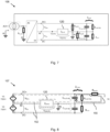
- Reference source not found. 7 illustrates three examples of fault situations that may be detected, limited and discriminated by the ZM protection circuit. These fault situations may be referred to as fault 1, 2, and 3, and their fault resistances as R fault1 , R fault2 , and R fault3 :
- R fault1/2/3 a possible fault
- R M-PE a possible fault
- the latter may provide a limiting effect for the fault current caused by the discharge of:
- i Z(M-PE) e.g., the sign thereof
- i R(M-PE) the ratio between R fault and R M-PE may be determined, and with that R fault may be derived (neglecting R Y since that will typically be of much higher value).
- R faultx V DCx /i R(M-PE) ) - R M-PE .
- V DC is a DC voltage at the respective positive or negative conductor.
- Fig. 10 shows additional fault locations and may be explained as follows.
- a fault condition to PE is experienced at the AC side (represented by the R fault3 in Fig. 10 but which may occur with respect to any of the AC phases)
- this typically causes also an imbalance in the operation of the DC section, as the AC/DC power converter has no isolation and its internal active or passive switches (semiconductors power components like IGBTs or diodes), due to their conduction action, connect alternately the DC side (DC+ or DC- terminals) to the AC side, which in turn causes a current to flow through the impedance Z M-PE 120.
- the AC fault currents through R fault3 may be detected in a similar way as explained for the DC side.
- the severity of the fault may be determined.
- the fault current i Z(M-PE) may contain AC components that may be detected by the fault protection circuit of the protection system. If such AC components are detected, the fault protection circuit may conclude that the current i Z(M-PE) is at least in part due to a fault condition to PE at the AC side.
- Fig. 10 shows the power conversion from AC to DC as a two-stage power conversion, namely as a first stage from AC to DC and as a second stage from DC to DC.
- there may be fault condition to PE at the DC input side of the second stage represented by R fault4 and R fault5 in Fig. 10 .
- Such fault conditions also typically cause an imbalance in the DC output side which again may cause a current to flow through the impedance Z M-PE 120.
- By measuring the current such fault currents through R fault4 and R fault5 may be detected in a similar way as previously explained for R fault1 and R fault2 , namely by measuring the magnitude and direction of the current i Z(M-PE) .
- the above-described protection system may be used as an IT circuit grounding method for DC systems with (high) capacitances to protective earth.
- the protection system may be used for monitoring, detecting and limiting of fault current in a symmetric IT circuit.
- the protection system may further help in voltage balancing and may limit ground fault currents to safe values with fast detection for protection against safety ground faults on DC and AC sides.
- the detection may be fast, for example typically 100 ms, in comparison to currently used IMD devices (10-60 seconds) since i Z(M-PE) is used to detect a fault instead of an indirect RC estimation.
- the protection system may detect a too low R IT-PE value based on the magnitude of the fault current.
- the protection system may further detect and limit permanent values of short-circuit of DC+ or DC- to PE, detect voltage imbalance in DC sections, and limit value of short-circuit current to predetermined values.
- the protection system may represent a passive method, free of injecting signal, that does not cause any interference or disturbance in the monitored DC system.
- the protection system may be deployed centrally to detect faults everywhere in the IT circuit, not only in the (symmetric) DC part of the system.
- the protection system may comprise one or more (micro)processors which execute appropriate software and which may implement certain functionality of the protection system, specifically the functionality of the fault detection circuit.
- the software may have been downloaded and/or stored in a corresponding memory or memories, e.g., in volatile memory such as RAM or in non-volatile memory such as Flash.
- the fault detection circuit may be implemented in the form of programmable logic, e.g., as a Field-Programmable Gate Array (FPGA).
- FPGA Field-Programmable Gate Array
- Fig. 11 shows a protection method 200 for a symmetric, isolated terra bipolar DC system.
- the method 200 may comprise providing 210 a predetermined impedance between the midpoint conductor and protective earth, and during operation 220 of the DC system, determining 230 a current flowing through at least a resistive part of the predetermined impedance, determining 240 a magnitude of the current, comparing 250 the magnitude of the current against a threshold, and triggering 260 a fault action if the magnitude of the current exceeds the threshold.
- the threshold may be chosen for human protection, for example as defined in IEC 60479-1 Part 1 with reference to the effects of current on human beings and livestock.
- the threshold may be chosen in accordance with automotive industry standards, for example as 10 mA as defined by SAE J1766 for continuous monitoring.
- a computer may be implemented on a computer as a computer implemented method, as dedicated hardware, or as a combination of both.
- Instructions for the computer e.g., executable code
- the executable code may be stored in a transitory or non-transitory manner. Examples of computer-readable mediums include memory devices, optical storage devices, integrated circuits, etc.
- Fig. 12 shows a memory card 300.
- any reference signs placed between parentheses shall not be construed as limiting the claim.
- Use of the verb "comprise” and its conjugations does not exclude the presence of elements or stages other than those stated in a claim.
- the article “a” or “an” preceding an element does not exclude the presence of a plurality of such elements.
- Expressions such as “at least one of” when preceding a list or group of elements represent a selection of all or of any subset of elements from the list or group.
- the expression, “at least one of A, B, and C” should be understood as including only A, only B, only C, both A and B, both A and C, both B and C, or all of A, B, and C.
- the invention may be implemented by means of hardware comprising several distinct elements, and by means of a suitably programmed computer.
- the device claim enumerating several means several of these means may be embodied by one and the same item of hardware.
- the mere fact that certain measures are recited in mutually different dependent claims does not indicate that a combination of these measures cannot be used to advantage.
Landscapes
- Engineering & Computer Science (AREA)
- Life Sciences & Earth Sciences (AREA)
- Sustainable Development (AREA)
- Sustainable Energy (AREA)
- Power Engineering (AREA)
- Transportation (AREA)
- Mechanical Engineering (AREA)
- Emergency Protection Circuit Devices (AREA)
Priority Applications (2)
| Application Number | Priority Date | Filing Date | Title |
|---|---|---|---|
| EP23213501.2A EP4564628A1 (fr) | 2023-11-30 | 2023-11-30 | Système de protection pour système cc bipolaire terra isolé |
| PCT/EP2024/083957 WO2025114462A1 (fr) | 2023-11-30 | 2024-11-28 | Système cc bipolaire isolé à la terre |
Applications Claiming Priority (1)
| Application Number | Priority Date | Filing Date | Title |
|---|---|---|---|
| EP23213501.2A EP4564628A1 (fr) | 2023-11-30 | 2023-11-30 | Système de protection pour système cc bipolaire terra isolé |
Publications (1)
| Publication Number | Publication Date |
|---|---|
| EP4564628A1 true EP4564628A1 (fr) | 2025-06-04 |
Family
ID=89029866
Family Applications (1)
| Application Number | Title | Priority Date | Filing Date |
|---|---|---|---|
| EP23213501.2A Pending EP4564628A1 (fr) | 2023-11-30 | 2023-11-30 | Système de protection pour système cc bipolaire terra isolé |
Country Status (2)
| Country | Link |
|---|---|
| EP (1) | EP4564628A1 (fr) |
| WO (1) | WO2025114462A1 (fr) |
Citations (5)
| Publication number | Priority date | Publication date | Assignee | Title |
|---|---|---|---|---|
| EP0360109B1 (fr) * | 1988-09-21 | 1994-06-01 | Asea Brown Boveri Ab | Dispositif protecteur pour une ligne d'électrodes |
| US20120019964A1 (en) * | 2010-07-23 | 2012-01-26 | Xantrex Technology Inc. | Photovoltaic bipolar to monopolar source circuit converter with frequency selective grounding |
| US20170131341A1 (en) * | 2013-10-08 | 2017-05-11 | Rockwell Automation Technologies, Inc. | System and method for ground fault detection |
| ES2716482A1 (es) * | 2018-12-18 | 2019-06-12 | Univ Madrid Politecnica | Sistema y metodo de deteccion de faltas a tierra o contra el chasis en sistemas de corriente continua con inversores alimentados a partir de baterias |
| WO2023007253A1 (fr) * | 2021-07-30 | 2023-02-02 | Abb Schweiz Ag | Dispositif et procédé de surveillance d'isolation à symétrie forcée |
-
2023
- 2023-11-30 EP EP23213501.2A patent/EP4564628A1/fr active Pending
-
2024
- 2024-11-28 WO PCT/EP2024/083957 patent/WO2025114462A1/fr active Pending
Patent Citations (5)
| Publication number | Priority date | Publication date | Assignee | Title |
|---|---|---|---|---|
| EP0360109B1 (fr) * | 1988-09-21 | 1994-06-01 | Asea Brown Boveri Ab | Dispositif protecteur pour une ligne d'électrodes |
| US20120019964A1 (en) * | 2010-07-23 | 2012-01-26 | Xantrex Technology Inc. | Photovoltaic bipolar to monopolar source circuit converter with frequency selective grounding |
| US20170131341A1 (en) * | 2013-10-08 | 2017-05-11 | Rockwell Automation Technologies, Inc. | System and method for ground fault detection |
| ES2716482A1 (es) * | 2018-12-18 | 2019-06-12 | Univ Madrid Politecnica | Sistema y metodo de deteccion de faltas a tierra o contra el chasis en sistemas de corriente continua con inversores alimentados a partir de baterias |
| WO2023007253A1 (fr) * | 2021-07-30 | 2023-02-02 | Abb Schweiz Ag | Dispositif et procédé de surveillance d'isolation à symétrie forcée |
Also Published As
| Publication number | Publication date |
|---|---|
| WO2025114462A1 (fr) | 2025-06-05 |
Similar Documents
| Publication | Publication Date | Title |
|---|---|---|
| Bhargav et al. | Novel fault detection and localization algorithm for low-voltage DC microgrid | |
| Cairoli et al. | Fault detection and isolation in medium-voltage DC microgrids: Coordination between supply power converters and bus contactors | |
| Yadav et al. | A real-time resistance based fault detection technique for zonal type low-voltage DC microgrid applications | |
| Rao et al. | Fault detection in DC microgrid based on the resistance estimation | |
| Mirsaeidi et al. | Towards hybrid AC/DC microgrids: Critical analysis and classification of protection strategies | |
| Muda et al. | Sequence currents based adaptive protection approach for DNs with distributed energy resources | |
| RU2584096C2 (ru) | Силовой переключатель постоянного напряжения | |
| US7969696B2 (en) | Ground fault detection and localization in an ungrounded or floating DC electrical system | |
| Monadi et al. | Multi‐terminal medium voltage DC grids fault location and isolation | |
| US12500512B2 (en) | Power converter for transferring power between an AC side and a DC side, and power supply method | |
| Redfern et al. | Protection of micro-grids dominated by distributed generation using solid state converters | |
| Allam et al. | A novel DC distance relay for MVDC microgrids | |
| EP2741094A1 (fr) | Dispositif de détection de défaut de terre, procédé de détection de défaut de terre, système d'énergie solaire et programme détection de défaut de terre | |
| Yadav et al. | Short-circuit fault detection and isolation using filter capacitor current signature in low-voltage DC microgrid applications | |
| MX2014010385A (es) | Hacer uso de redundancia inherente en un dispositivo electronico inteligente multifuncional. | |
| Nahas et al. | Developing a smart power-voltage relay (SPV-relay) with no communication system for DC microgrids | |
| Carminati et al. | DC and AC ground fault analysis in LVDC microgrids with energy storage systems | |
| Li et al. | Open‐circuit fault diagnosis for a fault‐tolerant three‐level neutral‐point‐clamped STATCOM | |
| Reddy O et al. | Fault detection and location estimation for LVDC microgrid using self‐parametric measurements | |
| Liu et al. | Detection of ground insulation faults in ungrounded DC power supply systems by using a DC current injection method | |
| Rao et al. | Novel differential protection strategy for zonal DC microgrid | |
| Wang et al. | A decentralized model-based fault detection and isolation scheme for MVDC shipboard power systems | |
| Sharanya et al. | Fault detection and location in DC microgrid | |
| US12438363B2 (en) | Method for operating a DC voltage grid and power converter for connecting a DC voltage grid to an AC voltage grid | |
| JP5828396B2 (ja) | 直流電源とその地絡検出方法 |
Legal Events
| Date | Code | Title | Description |
|---|---|---|---|
| PUAI | Public reference made under article 153(3) epc to a published international application that has entered the european phase |
Free format text: ORIGINAL CODE: 0009012 |
|
| STAA | Information on the status of an ep patent application or granted ep patent |
Free format text: STATUS: THE APPLICATION HAS BEEN PUBLISHED |
|
| AK | Designated contracting states |
Kind code of ref document: A1 Designated state(s): AL AT BE BG CH CY CZ DE DK EE ES FI FR GB GR HR HU IE IS IT LI LT LU LV MC ME MK MT NL NO PL PT RO RS SE SI SK SM TR |
|
| STAA | Information on the status of an ep patent application or granted ep patent |
Free format text: STATUS: THE APPLICATION IS DEEMED TO BE WITHDRAWN |