EP4564671A1 - Elektronisch schaltende schutzvorrichtung mit kühlkörper - Google Patents
Elektronisch schaltende schutzvorrichtung mit kühlkörper Download PDFInfo
- Publication number
- EP4564671A1 EP4564671A1 EP24216530.6A EP24216530A EP4564671A1 EP 4564671 A1 EP4564671 A1 EP 4564671A1 EP 24216530 A EP24216530 A EP 24216530A EP 4564671 A1 EP4564671 A1 EP 4564671A1
- Authority
- EP
- European Patent Office
- Prior art keywords
- electronic
- neutral
- cut
- connection terminal
- phase
- Prior art date
- Legal status (The legal status is an assumption and is not a legal conclusion. Google has not performed a legal analysis and makes no representation as to the accuracy of the status listed.)
- Pending
Links
Images


Classifications
-
- H—ELECTRICITY
- H03—ELECTRONIC CIRCUITRY
- H03K—PULSE TECHNIQUE
- H03K17/00—Electronic switching or gating, i.e. not by contact-making and –breaking
- H03K17/08—Modifications for protecting switching circuit against overcurrent or overvoltage
- H03K17/082—Modifications for protecting switching circuit against overcurrent or overvoltage by feedback from the output to the control circuit
- H03K17/0822—Modifications for protecting switching circuit against overcurrent or overvoltage by feedback from the output to the control circuit in field-effect transistor switches
-
- H—ELECTRICITY
- H01—ELECTRIC ELEMENTS
- H01H—ELECTRIC SWITCHES; RELAYS; SELECTORS; EMERGENCY PROTECTIVE DEVICES
- H01H71/00—Details of the protective switches or relays covered by groups H01H73/00 - H01H83/00
- H01H71/10—Operating or release mechanisms
- H01H71/12—Automatic release mechanisms with or without manual release
- H01H71/123—Automatic release mechanisms with or without manual release using a solid-state trip unit
-
- H—ELECTRICITY
- H01—ELECTRIC ELEMENTS
- H01H—ELECTRIC SWITCHES; RELAYS; SELECTORS; EMERGENCY PROTECTIVE DEVICES
- H01H83/00—Protective switches, e.g. circuit-breaking switches, or protective relays operated by abnormal electrical conditions otherwise than solely by excess current
- H01H83/20—Protective switches, e.g. circuit-breaking switches, or protective relays operated by abnormal electrical conditions otherwise than solely by excess current operated by excess current as well as by some other abnormal electrical condition
- H01H83/22—Protective switches, e.g. circuit-breaking switches, or protective relays operated by abnormal electrical conditions otherwise than solely by excess current operated by excess current as well as by some other abnormal electrical condition the other condition being imbalance of two or more currents or voltages
- H01H83/226—Protective switches, e.g. circuit-breaking switches, or protective relays operated by abnormal electrical conditions otherwise than solely by excess current operated by excess current as well as by some other abnormal electrical condition the other condition being imbalance of two or more currents or voltages with differential transformer
-
- H—ELECTRICITY
- H01—ELECTRIC ELEMENTS
- H01H—ELECTRIC SWITCHES; RELAYS; SELECTORS; EMERGENCY PROTECTIVE DEVICES
- H01H9/00—Details of switching devices, not covered by groups H01H1/00 - H01H7/00
- H01H9/52—Cooling of switch parts
-
- H—ELECTRICITY
- H01—ELECTRIC ELEMENTS
- H01H—ELECTRIC SWITCHES; RELAYS; SELECTORS; EMERGENCY PROTECTIVE DEVICES
- H01H9/00—Details of switching devices, not covered by groups H01H1/00 - H01H7/00
- H01H9/54—Circuit arrangements not adapted to a particular application of the switching device and for which no provision exists elsewhere
- H01H9/548—Electromechanical and static switch connected in series
-
- H—ELECTRICITY
- H02—GENERATION; CONVERSION OR DISTRIBUTION OF ELECTRIC POWER
- H02H—EMERGENCY PROTECTIVE CIRCUIT ARRANGEMENTS
- H02H3/00—Emergency protective circuit arrangements for automatic disconnection directly responsive to an undesired change from normal electric working condition with or without subsequent reconnection ; integrated protection
- H02H3/08—Emergency protective circuit arrangements for automatic disconnection directly responsive to an undesired change from normal electric working condition with or without subsequent reconnection ; integrated protection responsive to excess current
-
- H—ELECTRICITY
- H03—ELECTRONIC CIRCUITRY
- H03K—PULSE TECHNIQUE
- H03K17/00—Electronic switching or gating, i.e. not by contact-making and –breaking
- H03K17/08—Modifications for protecting switching circuit against overcurrent or overvoltage
- H03K17/082—Modifications for protecting switching circuit against overcurrent or overvoltage by feedback from the output to the control circuit
- H03K17/0828—Modifications for protecting switching circuit against overcurrent or overvoltage by feedback from the output to the control circuit in composite switches
-
- H—ELECTRICITY
- H03—ELECTRONIC CIRCUITRY
- H03K—PULSE TECHNIQUE
- H03K17/00—Electronic switching or gating, i.e. not by contact-making and –breaking
- H03K17/08—Modifications for protecting switching circuit against overcurrent or overvoltage
- H03K2017/0806—Modifications for protecting switching circuit against overcurrent or overvoltage against excessive temperature
-
- H—ELECTRICITY
- H03—ELECTRONIC CIRCUITRY
- H03K—PULSE TECHNIQUE
- H03K2217/00—Indexing scheme related to electronic switching or gating, i.e. not by contact-making or -breaking covered by H03K17/00
- H03K2217/0027—Measuring means of, e.g. currents through or voltages across the switch
Definitions
- the invention relates to the field of electronic cut-off protection devices with a heat sink.
- Electronic cut-off protection devices with a heat sink are known, for example, from the publication WO2022106527A1 or of the publication WO22243456 A1 These documents particularly concern finding a solution to efficiently evacuate the heat released by electronic power cut-off components, such as power transistors.
- the cut-off block comprising the power switches of a phase line between several conductive plates and the walls of the device housing, which has the advantage of allowing the dissipation of thermal energy and therefore reducing the number of semiconductor cut-off components.
- the thermal energy released by the switches is here dissipated to the outside of the device by conduction along the phase electrical conductors.
- the thermal energy is mainly dissipated by conduction and by radiation through the conductive parts to the outside of the device.
- the entire phase current flow chain inside the circuit breaker is concerned, i.e.
- phase current line all the electrical conductors, power supply cables and electrical conduction lines that allow the flow of phase current from upstream to downstream of the device.
- the power supply cables or electrical braids used on the phase electrical conduction lines do not have optimal thermal conduction properties and also involve tedious and meticulous assembly operations, particularly with the conductive plates.
- this solution requires significant modifications to the phase current line to allow the heat from the phase switches associated with the phase current line to be dissipated using the conductive plates.
- the present invention aims to overcome at least one of these drawbacks and aims to propose an alternative solution to the known prior art having a limited impact on the material of the housing and on the phase current line.
- the neutral conductive portion 11 is thermally interfaced with the electronic cut-off unit 8 comprising said at least one electronic power cut-off component 9 of the phase current line P while being electrically isolated therefrom. Thanks to this configuration, it is not the phase current line P that is used to dissipate the heat emanating from said at least one electronic power cut-off component 9 of the phase current line P, but counter-intuitively at least a portion of the neutral current line N that forms a heat sink 10 and allows the heat to be evacuated towards the first neutral connection terminal 4.
- the neutral conductive portion 11 can allow the flow of electric current in the direction from the second neutral connection terminal 5 to the first neutral connection terminal 4 or in the direction from the first neutral connection terminal 4 to the second neutral connection terminal 5.
- the neutral conductive portion 11 makes it possible to evacuate the heat coming from said at least one electronic power cut-off component 9 towards the first neutral connection terminal 4 by thermal conduction.
- the neutral conductive portion 11 is electrically insulated from said electronic cut-off unit 8 by an electrically insulating and thermally conductive element 13.
- the electrically insulating and thermally conductive element 13 makes it possible on the one hand to electrically insulate the neutral conductive portion 11 of the electronic cut-off unit 8 in order to respect the dielectric distances and avoid breakdowns and on the other hand to promote the conduction of heat coming from said electronic power cut-off component 9 from the phase current line P to the neutral current line N.
- the electronic cut-off protection apparatus comprises at least one phase compartment 14 comprising at least the first phase connection terminal 2, the second phase connection terminal 3 and said electronic cut-off unit 8, and a neutral compartment 15 comprising at least the first neutral connection terminal 4 associated with the neutral conductive portion 11 and the second neutral connection terminal 5, the phase compartment 14 and the neutral compartment 15 being separated by an insulating separating wall 16 comprising a passage 17 configured to allow thermal conduction from said electronic cut-off unit 8 to the neutral conductive portion 11.
- the creation in the housing 1 of the phase compartment 14 and the neutral compartment 15 makes it possible to divide the housing 1 at least into two parts and to physically separate said at least one phase current line P from the neutral current line N to respect the dielectric insulation between the potential of phase and neutral potential.
- the housing 1 may comprise as many phase compartments 14 as there are phase P current lines.
- the passage 17 further improves thermal conduction by providing direct access between the phase compartment 14 and the neutral compartment 15 and thus by limiting the number of interfaces between the neutral conductive portion 11 and the electronic cut-off unit 8.
- said electronic cut-off unit 8 comprises at least one electronic card 18 comprising a first face 19 and a second face 20 opposite the first face 19 and said electronic cut-off unit 8 comprises a first assembly E1 of at least one electronic power cut-off component 9 on said phase current line P mounted on the first face 19 or the second face 20 and a second assembly E2 of at least one electronic power cut-off component 9 on said phase current line P mounted on the first face 19 or the second face 20 and electrically connected head-to-tail to said at least one electronic power cut-off component 9 of the first assembly E1.
- the electronic card 18 is parallel to the insulating separating wall 16 and said at least one electronic power cut-off component 9 of the second assembly E2 is mounted on the first face 19 opposite the passage 17 and comprises a dissipating element (not shown) oriented against the first face 19 and an insulated face 21 oriented opposite, the neutral conductive portion 11 comprises a contact interface 22 which is arranged opposite and at a distance from the insulated face 21.
- said at least one electronic power cut-off component 9 of the second assembly E2 is opposite the neutral conductive portion 11 and therefore aligned with it, the thermal conduction is optimized while respecting the dielectric insulation distance.
- the evacuation of the heat coming from the electronic power cut-off components 9 of the second assembly E2 is carried out by thermal conduction, in particular furthermore in the neutral conductive portion 11 towards the first neutral connection terminal 4.
- a portion of the calories is also discharged towards the second neutral connection terminal 5 and where appropriate towards the second set of contacts.
- the insulated face of said at least one electronic power cut-off component 9 of the second set E2 is oriented against the first face 19 and the dissipating element is oriented opposite and that therefore the contact interface 22 is arranged opposite and at a distance from the dissipating element.
- the electrically insulating and thermally conductive element 13 is interposed between the insulated face 21 and the contact interface 22 and is arranged against both the insulated face 21 and the contact interface 22.
- the electrically insulating and thermally conductive element 13 makes it possible to physically maintain the dielectric insulation distance between the insulated face 21 of said at least one electronic power cut-off component 9 of the second assembly E2 and the contact interface 22 of the neutral conductive portion 11 while allowing thermal conduction.
- the electrically insulating element and the thermal conductor 13 could, according to the variant not shown described previously, make it possible to physically maintain the dielectric insulation distance between the dissipating element of said at least one electronic power cut-off component 9 of the second assembly E2 and the contact interface 22 of the neutral conductive portion 11 while allowing thermal conduction.
- the first/second neutral connection terminal 4, 5 comprises a conductive part 6 comprising at least one contact portion 7 configured to come into contact with a supply conductor of the network or of a load, the conductive part 6 of the first neutral connection terminal 4 is extended by the neutral conductive portion 11, the conductive part 6 and the neutral conductive portion 11 forming a single-piece conductive part 12.
- the conductive part 6 of the first/second neutral connection terminal 4, 5 incorporates a neutral conductive portion 11 which is thermally interfaced with the electronic cut-off unit 8 comprising said at least one electronic power cut-off component 9 of the line of phase current P by being electrically isolated therefrom.
- No connection by means of an electrical cable or electrical braid is used to connect the first/second neutral connection terminal 4, 5 to the heat sink 10 formed by the neutral conductive portion 11.
- the conductive part 6 and the neutral conductive portion 11 are in the form of a single-piece conductive part 12. This results in a reduction in the number of parts and an improvement in the assembly operations of the electronic cut-off protection device and heat dissipation by thermal conduction along the phase current line N.
- the single-piece conductive part 12 is made of metal and preferably copper.
- the electronic cut-off protection apparatus further comprises a galvanic isolation mechanism comprising a first set of contacts with a first fixed contact 23 and a first movable contact arranged on the phase current line P in series with said at least one electronic power cut-off component 9 and a second set of contacts with a second fixed contact 24 and a second movable contact arranged on the neutral current line N upstream or downstream of the neutral conductive portion 11.
- a galvanic isolation mechanism comprising a first set of contacts with a first fixed contact 23 and a first movable contact arranged on the phase current line P in series with said at least one electronic power cut-off component 9 and a second set of contacts with a second fixed contact 24 and a second movable contact arranged on the neutral current line N upstream or downstream of the neutral conductive portion 11.
- the galvanic isolation mechanism makes it possible to isolate the electronic cut-off protection device, in particular after the opening of said at least one electronic power cut-off component 9 following the occurrence of a fault, by interrupting the flow of current on the phase current line P and the neutral current line N.
- the neutral current line N is free of electronic power cut-off components.
- the neutral current line N cannot be interrupted by the electronic protection trip unit and the electronic switching unit 8 when a fault occurs.
- the separation of the second set of contacts from the neutral current line N can be controlled by the electronic protection trip unit in the event of a fault occurring.
- said at least one electronic power cut-off component 9 comprises at least one power transistor and preferably at least one MOSFET and/or one JFET and/or one IGBT.
- the housing 1 preferably has a generally parallelepiped shape with a first main face (not shown) and a second main face (not shown), and lateral faces, respectively rear 25, upper 26, lower 27, front (not shown) extending from one to the other of the first and second main faces and with a width, that is to say the gap between the first and second main faces, equal to an integer number of times a predetermined distance, called module generally worth approximately 18 millimeters.
- the format of the housing 1 is modular and this results in a modular electronic cut-off protection device.
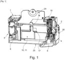
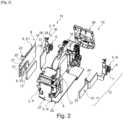
- the electronic cut-off protection device shown in figures 1 to 5 has a width of two modules. This example is not exhaustive.
- the electronic cut-off protection device may comprise a phase P current line, or several phase P current lines, and in all cases it also comprises a neutral current line.
- figures 1 to 5 illustrate an electronic cut-off protection device with a phase current line P and a neutral current line N.
- the electronic cut-off protection device can be a circuit breaker or perform a differential circuit breaker protection function, but also other functions, such as current and voltage measurement, protection against electric arc faults in the installation.
- the electronic cut-off protection device When the electronic cut-off protection device performs a differential circuit breaker protection function, it preferably comprises a differential current sensor (not shown) for detecting faults of the differential fault type and which is connected to the control unit.
- the differential current sensor is capable and intended at least to measure the differential current flowing between said at least one phase current line P and the neutral current line N and to emit an acquisition signal representative of the image of the differential current between the phase current line P and the neutral current line N. neutral N.
- the differential current sensor allows differential faults to be detected.
- the first phase connection terminal 2 and the first neutral connection terminal 4 may be a screw cage terminal or a spring-type self-clamping terminal or the like.
- the first phase connection terminal 2 and the first neutral connection terminal 4 are each a spring-type self-clamping terminal and are arranged inside the housing 1 near the upper side face 26.
- the second phase connection terminal 3 and the second neutral connection terminal 5 may be a screw cage terminal or a spring-type or similar self-clamping terminal and/or a mixed self-clamping cage and screw terminal.
- the second phase connection terminal 3 and the second neutral connection terminal 5 are each a mixed self-clamping cage and screw terminal and are arranged inside the housing 1 near the lower side face 27.
- the first phase 2 or neutral 4 connection terminals each comprise a conductive part 6 comprising at least one contact portion 7 configured to come into contact with a power supply conductor of the network or a load.
- the conductive part 6 comprises an elastically deformable metal part which makes it possible to clamp at least one power supply conductor of the network or a load at the contact portion 7.
- this elastically deformable metal part comprises two elastic branches joining together.
- the two conductive parts 6 are arranged inside the housing 1 near the upper lateral face 26.
- the control unit (not shown) of the electronic protection trip unit is electrically connected to the electronic cut-off unit 8.
- the control unit and the electronic cut-off unit 8 are arranged inside the housing 1.
- the control unit may include at least one microcontroller and at least one power driver.
- the control unit and the electronic cut-off unit 8 may respectively comprise one or more electronic cards.
- the control unit and the electronic cut-off unit 8 could alternatively comprise a single electronic card comprising said microcontroller and said power driver and said at least one electronic power cut-off component 9.
- the electronic cut-off unit 8 and the control unit are not grouped on the same electronic card, but on at least two separate electronic cards electrically and mechanically connected to each other, only the electronic card 18 is shown.
- the electronic cut-off unit 8 comprises the electronic card 18 on which said at least one electronic power cut-off component 9 is mounted and preferably integrated.
- the electronic card 18 is arranged in the phase compartment 14 preferably parallel to the first and second main faces of the housing 1 and to the insulating separating wall 16 and extends in the length direction in a space located between the first and second phase connection terminals 2, 3, in the width direction in a space located between the rear lateral face 25 and the front lateral face, and in the thickness direction in a space located between the second main face and the insulating separating wall 16.
- the electronic card 18 is preferably arranged at least partly opposite the second main face.
- the first set E1 of electronic power cut-off component 9 and the second set E2 of electronic power cut-off component 9 are preferably mounted in series, for example head-to-tail, on the phase current line P.
- the first assembly E1 and the second assembly E2 each have two electronic power cut-off components 9.
- the first assembly E1 comprises at least two electronic power cut-off components 9 in the same direction and mounted in parallel.
- the second set E2 comprises at least two electronic power cut-off components 9 in the same direction and mounted in parallel.
- the dissipating element (not shown) of the electronic power cut-off component 9 is generally made of metal.
- the dissipating element may be in the form of a metal plate, corresponding to the drain of the electronic power cut-off component 9, which is arranged opposite the insulated face 21.
- the drain may also perform an electrical connection function with an attached dissipating element described below. This may for example be the case when the drain is located at the face of the electronic power cut-off component 9, which may be the upper face, not resting against one of the faces 19, 20 of the electronic card 18. However, when the drain is located on the face of the electronic power cut-off component 9, which may be the lower face, which rests on one of the faces 19, 20 of the electronic card 18, the drain does not perform an electrical connection function with an attached dissipating element.
- the dissipating element may be a separate part attached to the electronic power cut-off component 9 and in particular not corresponding to the drain.
- the dissipating element may in this case be in the form of a part provided with a plurality of fins. Either this dissipating element is not in electrical contact with the drain of the electronic power cut-off component 9 and is mounted on the insulated face 21, or this dissipating element may be in electrical contact with the drain of the electronic power cut-off component 9.
- the drain must be located at the level of the face of the electronic power cut-off component 9 not resting against one of the faces 19, 20 of the electronic card 18.
- the neutral conductive portion 11 forming a heat sink 10 may preferably be in the form of a flat part or flat plate with or without a folding zone.
- the flat part or flat plate is arranged in the housing 1 parallel to the first and second main faces, to the insulating separating wall 16 and to the electronic card 18 and in the neutral compartment 15.
- the flat part or flat plate extends in the length direction in a space located between the first and second neutral connection terminals 4, 5, in the width direction in a space located between the rear side face 25 and the front side face, and in the thickness direction in a space located between the first main face and the insulating separating wall 16
- the neutral conductive portion 11 is located in the extension of the contact portion 7 of the first neutral connection terminal 4.
- a single-piece conductive part 12 is understood to mean a part formed in one piece, for example by folding or stamping, for example, a preferably metallic conductive part.
- the preferably conductive contact portion 7 and the neutral conductive portion 11 are not two distinct and separate parts; there is no junction by mechanical connection between two distinct parts and which would be formed between the contact portion 7 and the neutral conductive portion 11.
- the electrically insulating and thermally conductive element 13 preferably comprises a thermally conductive and electrically insulating material, for example a polymer such as a polyimide or a non-metallic mineral material such as ceramic.
- the electrically insulating and thermally conductive element 13 may be in the form of a flat plate, for example of substantially rectangular shape and which covers the second assembly E2 of electronic power cut-off component 9.
- the electrically insulating and thermally conductive element 13 is preferably arranged in the phase compartment 14.
- the insulating partition wall 16 is preferably made of a polymeric material such as plastic.
- the passage 17 preferably has a substantially rectangular shape.
- the passage 17 is preferably covered by said electrically insulating and thermally conductive element 13.
- the passage 17 leaves free access to the second set E2 of electronic power cut-off components 9 which are electrically but not thermally insulated by said electrically insulating and thermally conductive element 13.
- the electronic cut-off protection device comprises a phase conductive portion 28 forming on the one hand at least a first part of the phase current line P and on the other hand an additional heat sink 29 and being electrically connected between the first phase connection terminal 2 and the second phase connection terminal 3.
- the phase conductive portion 28 forming an additional heat sink 29 may preferably be in the form of a flat part or flat plate.
- the flat part or flat plate is arranged in the housing 1 parallel to the first and second main faces and to the electronic card 18. Furthermore, the flat part or flat plate is arranged opposite the first face 19 of the electronic card 18 on an area devoid of the second assembly E2 of electronic power cut-off components 9 and opposite the insulating separating wall 16.
- the phase conductive portion 28 is located in the extension of the conductive part 6 of the first phase connection terminal 2.
- the conductive part 6 of the first phase connection terminal 2 and the phase conductive portion 28 can form a single-piece phase conductive part 30.
- a single-piece phase conductive part 30 is understood to mean a part formed in one piece, for example by folding or stamping, for example, a preferably metallic conductive part.
- the conductive part 6, preferably made of electrically conductive material, and the phase conductive portion 28 are not two distinct and separate parts; there is no junction by mechanical connection between two distinct parts that would be formed between the conductive part 6 and the phase conductive portion 28.
- the phase conductive portion 28 comprises a contact interface 31 which is arranged opposite the first face 19, against the latter and being aligned with said at least one electronic power cut-off component 9 of the first assembly E1 and is electrically and thermally connected to the electronic card 18 without electrical and thermal contact. direct with said at least one electronic power cut-off component 9 of the first assembly E1.
- the first face 19 of the electronic card 18 may comprise a conductive layer (not shown) of the equipotential track or plane type which is in direct contact on the one hand with the contact interface 31 of the phase conductive portion 28 and on the other hand with said at least one electronic power cut-off component 9 of the first assembly E1.
- This conductive layer may be connected to the contact interface 31 by a solder material.
- the first fixed contact 23 is preferably mounted on the electronic card 18. As illustrated by the figures 1 to 5 , the first fixed contact 23 is mounted protruding from the second face 20.
- the first fixed contact 23 may consist of a metal plate curved at 90 degrees having a general L shape, the longest portion of which is preferably mounted by welding or brazing on the second face 20 and the shortest portion is orthogonal to the second face 20.
- the second fixed contact 24 is preferably part of the neutral conductive portion 11.
- the first movable contact and the second movable contact can be actuated by a lever-type operating member (not shown). This lever preferably projects from the front side face.
- THE figures 1 to 5 illustrate a modular phase-neutral electronic cut-off protection device which has a width of two modules.
- the modular electronic cut-off protection device comprises the galvanic isolation mechanism comprising the first set of contacts with the first fixed contact 23 and the first movable contact arranged on the phase current line P in series with the electronic power cut-off components 9 upstream of the first phase connection terminal 2 and the second set of contacts with the second fixed contact 24 and the second movable contact arranged on the neutral current line N upstream of the neutral conductive portion 11.
- the conductive part 6 of the first neutral connection terminal 4 and the neutral conductive portion 11 form a single-piece conductive part 12.
- the conductive part 6 of the first phase connection terminal 2 and the phase conductive portion 28 form a single-piece conductive part 12.
- the interior of the housing 1 is divided into two compartments, namely the phase compartment 14 and the neutral compartment 15 by the insulating separating wall 16.
- the phase compartment 14 comprises the first phase connection terminal 2 associated with the phase conductive portion 28, the second phase connection terminal 3, said electronic cut-off unit 8 and the electrically insulating and thermally conductive element 13.
- the neutral compartment 15 comprises the first neutral connection terminal 4 associated with the neutral conductive portion 11 and the second neutral connection terminal 5.
- the insulating separating wall 16 comprises the passage 17 configured to allow thermal conduction from said electronic cut-off unit 8 to the neutral conductive portion 11.
- the electronic cut-off unit 8 comprises a single electronic card 18 with the first assembly E1 having two electronic power cut-off components 9 on said phase current line P mounted on the second face 20 and the second assembly E2 comprising two electronic power cut-off components 9 on said phase current line P mounted on the first face 19.
- the two electronic power cut-off components 9 of the second assembly E2 are electrically connected in series in a head-to-tail manner with the two electronic power cut-off components 9 of the first assembly E1.
- the two electronic power cut-off components 9 of the first assembly E1 and of the second assembly E2 each comprise the dissipating element (not visible) in the form of a plate oriented respectively against the second face 20 and the first face 19 and the insulated face 21 oriented opposite.
- the first fixed contact 23 is mounted on the electronic card 18 while projecting from the second face 20.
- the electronic card 18 is parallel to the insulating separating wall 16.
- the electronic power cut-off components 9 of the second assembly E2 are aligned with the passage 17.
- the contact interface 22 of the neutral conductive portion 11 is parallel to the insulating separating wall 16 and is aligned with the passage 17 and with the two insulated upper faces 21 while being at a distance from them.
- the electrically insulating and thermally conductive element 13 is interposed between the insulated upper faces 21 and the contact interface 22 and is arranged against both the insulated upper faces 21 and the contact interface 22.
- the electronic power cut-off components 9 of the second assembly E2 are aligned with the passage 17.
- the contact interface 31 of the phase conductive portion 28 is arranged opposite the first face 19, against the latter and being aligned with the two electronic power cut-off components 9 of the first set E1 and is electrically and thermally connected to the electronic card 18 without direct electrical and thermal contact with the two electronic power cut-off components 9 of the first set E1.
- the heat evacuation from the electronic power cut-off components 9 of the second assembly E2 is carried out by thermal conduction in addition in the single-piece conductive part 12 towards the first neutral connection terminal 4 and the heat evacuation from the electronic power cut-off components 9 of the first assembly E1 is carried out in addition by thermal conduction in the single-piece phase conductive part 30 towards the first phase connection terminal 2.
- a portion of the calories from the electronic power cut-off components 9 of the second assembly E2 is also evacuated towards the second neutral connection terminal 5 and towards the second set of contacts.
- a portion of the calories from the electronic power cut-off components 9 of the first assembly E1 is also evacuated towards the second phase connection terminal 3 and towards the first set of contacts.
Landscapes
- Engineering & Computer Science (AREA)
- Power Engineering (AREA)
- Emergency Protection Circuit Devices (AREA)
- Cooling Or The Like Of Electrical Apparatus (AREA)
Applications Claiming Priority (1)
| Application Number | Priority Date | Filing Date | Title |
|---|---|---|---|
| FR2313365A FR3156237A1 (fr) | 2023-11-30 | 2023-11-30 | Appareillage de protection à coupure électronique avec dissipateur thermique |
Publications (1)
| Publication Number | Publication Date |
|---|---|
| EP4564671A1 true EP4564671A1 (de) | 2025-06-04 |
Family
ID=89977974
Family Applications (1)
| Application Number | Title | Priority Date | Filing Date |
|---|---|---|---|
| EP24216530.6A Pending EP4564671A1 (de) | 2023-11-30 | 2024-11-29 | Elektronisch schaltende schutzvorrichtung mit kühlkörper |
Country Status (2)
| Country | Link |
|---|---|
| EP (1) | EP4564671A1 (de) |
| FR (1) | FR3156237A1 (de) |
Citations (5)
| Publication number | Priority date | Publication date | Assignee | Title |
|---|---|---|---|---|
| US20110115585A1 (en) * | 2009-11-16 | 2011-05-19 | Square D Company | Low cost multi-pole circuit breakers with shared components |
| US20150040583A1 (en) * | 2013-08-06 | 2015-02-12 | Hyundai Motor Company | Heat dissipation device for electronic controllers |
| WO2022106527A1 (fr) | 2020-11-18 | 2022-05-27 | Hager-Electro Sas | Appareillage de protection à coupure électronique |
| WO2022243419A1 (fr) * | 2021-05-20 | 2022-11-24 | Schneider Electric Industries Sas | Appareils et systèmes de protection électrique |
| WO2022243456A1 (fr) | 2021-05-20 | 2022-11-24 | Schneider Electric Industries Sas | Appareils et systèmes de protection électrique comportant un module de coupure intégré |
-
2023
- 2023-11-30 FR FR2313365A patent/FR3156237A1/fr active Pending
-
2024
- 2024-11-29 EP EP24216530.6A patent/EP4564671A1/de active Pending
Patent Citations (5)
| Publication number | Priority date | Publication date | Assignee | Title |
|---|---|---|---|---|
| US20110115585A1 (en) * | 2009-11-16 | 2011-05-19 | Square D Company | Low cost multi-pole circuit breakers with shared components |
| US20150040583A1 (en) * | 2013-08-06 | 2015-02-12 | Hyundai Motor Company | Heat dissipation device for electronic controllers |
| WO2022106527A1 (fr) | 2020-11-18 | 2022-05-27 | Hager-Electro Sas | Appareillage de protection à coupure électronique |
| WO2022243419A1 (fr) * | 2021-05-20 | 2022-11-24 | Schneider Electric Industries Sas | Appareils et systèmes de protection électrique |
| WO2022243456A1 (fr) | 2021-05-20 | 2022-11-24 | Schneider Electric Industries Sas | Appareils et systèmes de protection électrique comportant un module de coupure intégré |
Also Published As
| Publication number | Publication date |
|---|---|
| FR3156237A1 (fr) | 2025-06-06 |
Similar Documents
| Publication | Publication Date | Title |
|---|---|---|
| EP0076719B1 (de) | Mehrpoliger Schutzschalter mit auswechselbarer Auslöseeinheit | |
| EP4341972B1 (de) | Elektrische geräte und schutzsysteme | |
| EP4341973B1 (de) | Elektrische geräte und schutzsysteme mit einem integrierten schaltmodul | |
| WO2010105920A1 (fr) | Ensemble de commande comportant un variateur de vitesse et un disjoncteur | |
| FR2831320A1 (fr) | Appareil de coupure a systeme de rail collecteur multiphase | |
| EP2536261B1 (de) | Elektronisches Leistungsmodul mit integrierter Kapazität | |
| EP4564671A1 (de) | Elektronisch schaltende schutzvorrichtung mit kühlkörper | |
| EP1667179B1 (de) | Elektrische Schaltvorrichtung mit Wiederverwendung von Schaltgasen | |
| EP3736926B1 (de) | Vorrichtung, die einen elektrischen leiter und ein gehäuse umfasst | |
| FR3005781A1 (fr) | Chambre de coupure pour un appareil de protection electrique et appareil de protection electrique la comportant. | |
| EP4564391A1 (de) | Elektronisch schaltende schutzvorrichtung mit kühlkörper | |
| EP1376637B1 (de) | Elektromagnetische Steuerungs- und Schutzvorrichtung | |
| EP1569303B1 (de) | Versorgungsrückleitungsvorrichtung für Flugzeugausrüstung | |
| FR3156255A1 (fr) | Appareillage de protection à coupure électronique | |
| FR3030867A1 (fr) | Chambre de coupure d'arc pour un disjoncteur electrique, et disjoncteur comportant une telle chambre. | |
| EP3696839B1 (de) | Schutzvorrichtung von mindestens zwei elektrokabeln gegen einen lichtbogen | |
| FR2879019A1 (fr) | Dispositif electrique de coupure avec chambre d'extinction d'arc a ailettes de desionisation | |
| FR2990793A1 (fr) | Disjoncteur a boitier moule | |
| FR3110034A1 (fr) | Module electrique avec surmoulage et systemes comprenant un tel module electrique | |
| FR2739978A1 (fr) | Bornier electrique | |
| FR3101193A1 (fr) | Appareil de coupure électrique à fusible | |
| FR3080494A1 (fr) | Dispositif de raccordement pour appareil electrique, appareil electrique comprenant ledit dispositif de raccordement et coffret de distribution associe | |
| FR2873501A1 (fr) | Boitier modulaire a cablage traversant | |
| EP3389141B1 (de) | Vorrichtung zur mechanischen halterung eines leitungsdrahtbündels | |
| FR3147004A1 (fr) | Unité électronique de détection d’au moins un défaut électrique pour un appareillage électrique de protection au format modulaire et appareillage électrique de protection au format modulaire associé |
Legal Events
| Date | Code | Title | Description |
|---|---|---|---|
| PUAI | Public reference made under article 153(3) epc to a published international application that has entered the european phase |
Free format text: ORIGINAL CODE: 0009012 |
|
| STAA | Information on the status of an ep patent application or granted ep patent |
Free format text: STATUS: THE APPLICATION HAS BEEN PUBLISHED |
|
| AK | Designated contracting states |
Kind code of ref document: A1 Designated state(s): AL AT BE BG CH CY CZ DE DK EE ES FI FR GB GR HR HU IE IS IT LI LT LU LV MC ME MK MT NL NO PL PT RO RS SE SI SK SM TR |
|
| STAA | Information on the status of an ep patent application or granted ep patent |
Free format text: STATUS: REQUEST FOR EXAMINATION WAS MADE |
|
| 17P | Request for examination filed |
Effective date: 20251202 |