EP4564700A1 - Gestion de faisceau - Google Patents
Gestion de faisceau Download PDFInfo
- Publication number
- EP4564700A1 EP4564700A1 EP24200247.5A EP24200247A EP4564700A1 EP 4564700 A1 EP4564700 A1 EP 4564700A1 EP 24200247 A EP24200247 A EP 24200247A EP 4564700 A1 EP4564700 A1 EP 4564700A1
- Authority
- EP
- European Patent Office
- Prior art keywords
- orientation
- rsrp
- time instance
- determining
- reference signal
- Prior art date
- Legal status (The legal status is an assumption and is not a legal conclusion. Google has not performed a legal analysis and makes no representation as to the accuracy of the status listed.)
- Pending
Links
Images





Classifications
-
- H—ELECTRICITY
- H04—ELECTRIC COMMUNICATION TECHNIQUE
- H04B—TRANSMISSION
- H04B17/00—Monitoring; Testing
- H04B17/30—Monitoring; Testing of propagation channels
- H04B17/309—Measuring or estimating channel quality parameters
- H04B17/318—Received signal strength
- H04B17/328—Reference signal received power [RSRP]; Reference signal received quality [RSRQ]
-
- H—ELECTRICITY
- H04—ELECTRIC COMMUNICATION TECHNIQUE
- H04B—TRANSMISSION
- H04B7/00—Radio transmission systems, i.e. using radiation field
- H04B7/02—Diversity systems; Multi-antenna system, i.e. transmission or reception using multiple antennas
- H04B7/04—Diversity systems; Multi-antenna system, i.e. transmission or reception using multiple antennas using two or more spaced independent antennas
- H04B7/06—Diversity systems; Multi-antenna system, i.e. transmission or reception using multiple antennas using two or more spaced independent antennas at the transmitting station
- H04B7/0686—Hybrid systems, i.e. switching and simultaneous transmission
- H04B7/0695—Hybrid systems, i.e. switching and simultaneous transmission using beam selection
- H04B7/06952—Selecting one or more beams from a plurality of beams, e.g. beam training, management or sweeping
-
- H—ELECTRICITY
- H04—ELECTRIC COMMUNICATION TECHNIQUE
- H04B—TRANSMISSION
- H04B7/00—Radio transmission systems, i.e. using radiation field
- H04B7/02—Diversity systems; Multi-antenna system, i.e. transmission or reception using multiple antennas
- H04B7/04—Diversity systems; Multi-antenna system, i.e. transmission or reception using multiple antennas using two or more spaced independent antennas
- H04B7/08—Diversity systems; Multi-antenna system, i.e. transmission or reception using multiple antennas using two or more spaced independent antennas at the receiving station
- H04B7/0868—Hybrid systems, i.e. switching and combining
- H04B7/088—Hybrid systems, i.e. switching and combining using beam selection
-
- H—ELECTRICITY
- H04—ELECTRIC COMMUNICATION TECHNIQUE
- H04B—TRANSMISSION
- H04B7/00—Radio transmission systems, i.e. using radiation field
- H04B7/02—Diversity systems; Multi-antenna system, i.e. transmission or reception using multiple antennas
- H04B7/04—Diversity systems; Multi-antenna system, i.e. transmission or reception using multiple antennas using two or more spaced independent antennas
- H04B7/0404—Diversity systems; Multi-antenna system, i.e. transmission or reception using multiple antennas using two or more spaced independent antennas the mobile station comprising multiple antennas, e.g. to provide uplink diversity
-
- H—ELECTRICITY
- H04—ELECTRIC COMMUNICATION TECHNIQUE
- H04W—WIRELESS COMMUNICATION NETWORKS
- H04W24/00—Supervisory, monitoring or testing arrangements
- H04W24/10—Scheduling measurement reports ; Arrangements for measurement reports
Definitions
- Example embodiments may relate to an apparatus, method and/or computer program for beam management, in particular, for rotating user devices.
- Communication systems enable communication between two or more nodes or devices, such as fixed or mobile communication devices. Signals can be carried on wireless carriers.
- LTE long-term evolution
- UMTS Universal Mobile Telecommunications System
- 3GPP 3rd Generation Partnership Project
- LTE long-term evolution
- UMTS Universal Mobile Telecommunications System
- E-UTRA evolved UMTS Terrestrial Radio Access
- LTE Long Term Evolution
- base stations, network nodes or access points, which are referred to as enhanced Node AP or Evolved Node B (eNBs) provide wireless access within a coverage area or cell.
- eNBs Evolved Node B
- UE user equipment's
- LTE has included a number of improvements or developments.
- 5G New Radio (NR) development is part of a continued mobile broadband evolution process to meet the requirements of 5G, similar to earlier evolution of 3G & 4G wireless networks.
- 5G is also targeted at the new emerging use cases in addition to mobile broadband.
- a goal of 5G is to provide significant improvement in wireless performance, which may include new levels of data rate, latency, reliability, and security.
- 5G NR may also scale to efficiently connect the massive Internet of Things (IoT), and may offer new types of mission-critical services.
- Ultra-reliable and low-latency communications (URLLC) devices may require high reliability and very low latency.
- a standardized set of operations for supporting beamforming transmission, including beam sweeping, beam measurements and reporting, beam maintenance and recovery is provided for 5G NR technology.
- an apparatus comprising means for determining a first orientation of the apparatus at a first time instance.
- the apparatus further comprise means for receiving, at substantially the first time instance, a reference signal from a network node and means for determining a reference signal received power, RSRP, value of the reference signal.
- the apparatus further comprise means for determining a second orientation of the apparatus at a second time instance and the second time instance is later than the first time instance.
- the apparatus further comprise means for determining a difference metric between the first orientation and second orientation and means for, upon determining that the difference metric is greater than a predetermined threshold value, processing the RSRP value, based on the difference metric, to provide a refined RSRP value.
- the apparatus further comprises means for determining that a rotation of the apparatus has occurred.
- the first orientation and second orientation are determined per a synchronization signal block, SSB, measurement or a synchronisation signal burst, SS-burst, time instance.
- the difference metric comprises a distance between the first orientation and the second orientation.
- the difference metric comprises a factor to account for angle wrapping at a coordinate system used to calculate the distance.
- the apparatus further comprises means for mapping the RSRP value to a representation of the RSRP value in a directional space.
- the apparatus further comprises means for calculating a rotation angle of the apparatus.
- the rotation angle is calculated as a distance between the first orientation and the second orientation and means for rotating the representation of the RSRP value by the rotation angle to produce a refined RSRP value.
- the apparatus further comprises means for obtaining a plurality of refined RSRP values for a plurality of reference signals and means for combining the plurality of refined RSRP values to produce an aggregated representation in the directional space.
- the apparatus further comprises means for determining an optimum user equipment, UE, beam from the aggregated representation.
- the optimum UE beam is determined based on a strength associated with the aggregated representation in the directional space.
- the apparatus further comprises means for commencing a wireless communication session with the network node, based on the optimum UE beam.
- the apparatus comprises a user equipment, UE.
- the means comprise: at least one processor; and at least one memory storing instructions that, when executed by the at least one processor, cause the performance of the apparatus.
- an apparatus comprising means for determining a first orientation of the apparatus at a first time instance.
- the apparatus further comprises means for receiving, at substantially the first time instance, a reference signal from a network node and means for determining a reference signal received power, RSRP, value of the reference signal.
- the apparatus further comprises means for determining a second orientation of the apparatus at a second time instance. The second time instance is later than the first time instance.
- the apparatus further comprises means for mapping the RSRP value to a representation of the RSRP value in a directional space and means for calculating a rotation angle of the apparatus. The rotation angle is calculated as a distance between the first orientation and the second orientation.
- the apparatus further comprises means for rotating the representation of the RSRP value by the rotation angle to produce a refined RSRP value.
- the apparatus further comprises means for obtaining a plurality of refined RSRP values for a plurality of reference signals and means for combining the plurality of refined RSRP values to produce an aggregated representation in the directional space.
- the apparatus further comprises means for determining an optimum user equipment, UE, beam from the aggregated representation.
- the optimum UE beam is determined based on a strength associated with the aggregated representation in the directional space.
- the apparatus further comprises means for commencing a wireless communication session with the network node, based on the optimum UE beam.
- the apparatus comprises a user equipment, UE.
- the means comprise: at least one processor; and at least one memory storing instructions that, when executed by the at least one processor, cause the performance of the apparatus.
- a method comprising determining a first orientation of an apparatus at a first time instance and receiving, at substantially the first time instance, a reference signal from a network node.
- the method further comprises determining a reference signal received power, RSRP, of the reference signal and determining a second orientation of the apparatus at a second time instance.
- the second time instance is later than the first time instance.
- the method further comprises determining a difference metric between the first orientation and second orientation and upon determining that the difference metric is greater than a predetermined threshold value, processing the RSRP, based on the difference metric, to provide a refined RSRP.
- a method comprising determining a first orientation of an apparatus at a first time instance and receiving, at substantially the first time instance, a reference signal from a network node.
- the method further comprises determining a reference signal received power, RSRP, value of the reference signal and determining a second orientation of the apparatus at a second time instance.
- the second time instance is later than the first time instance.
- the method further comprises mapping the RSRP value to a representation of the RSRP value in a directional space and calculating a rotation angle of the apparatus, wherein the rotation angle is calculated as a distance between the first orientation and the second orientation.
- the method further comprises rotating the representation of the RSRP value by the rotation angle to produce a refined RSRP value.
- an apparatus comprising at least one processor and at least one memory storing instructions that, when executed by the at least one processor, cause the apparatus to perform (at least) any method as described herein (including the method of the third aspect or the method of the fourth aspect described above).
- a non-transitory computer readable medium comprising program instructions stored thereon for performing a method, comprising determining a first orientation of an apparatus at a first time instance and receiving, at substantially the first time instance, a reference signal from a network node.
- the method further comprises determining a reference signal received power, RSRP, of the reference signal and determining a second orientation of the apparatus at a second time instance.
- the second time instance is later than the first time instance.
- the method further comprises determining a difference metric between the first orientation and second orientation and upon determining that the difference metric is greater than a predetermined threshold value, processing the RSRP, based on the difference metric, to provide a refined RSRP.
- a non-transitory computer readable medium comprising determining a first orientation of an apparatus at a first time instance and receiving, at substantially the first time instance, a reference signal from a network node.
- the method further comprises determining a reference signal received power, RSRP, value of the reference signal and determining a second orientation of the apparatus at a second time instance.
- the second time instance is later than the first time instance.
- the method further comprises mapping the RSRP value to a representation of the RSRP value in a directional space and calculating a rotation angle of the apparatus, wherein the rotation angle is calculated as a distance between the first orientation and the second orientation.
- the method further comprises rotating the representation of the RSRP value by the rotation angle to produce a refined RSRP value.
- some embodiments provide a beam management procedure for use during user equipment rotation.
- Example embodiments may relate to an apparatus, method and/or computer program for beam management.
- RSRP reference signal received power
- Example embodiments relate to an apparatus, method and/or computer program in which a UE may determine an RSRP value at a first time instance and determine whether to adjust this RSRP value based on a determined change in orientation of the UE.
- Example embodiments also relate to an apparatus, method and/or computer program in which a UE may determine a refined RSRP value based on a determined rotation angle between the UE at a first orientation and a second orientation.
- FIG. 1 shows, by way of an example, a network architecture of a communication system which is a radio access network (RAN).
- RAN radio access network
- LTE Advanced long term evolution advanced
- NR new radio
- Embodiments may also be applied to other kinds of communications networks having suitable means by adjusting parameters and procedures appropriately.
- radio access network radio access network
- LTE long term evolution
- WLAN wireless local area network
- WiFi worldwide interoperability for microwave access
- WiMAX wireless local area network
- Bluetooth ® personal communications services
- PCS personal communications services
- ZigBee ® wideband code division multiple access
- WCDMA wideband code division multiple access
- UWB ultra-wideband
- sensor networks mobile ad-hoc networks
- MANETs mobile ad-hoc networks
- IMS Internet Protocol multimedia subsystems
- FIG. 1 shows first and second user devices (which may be interchangeably referred to as user equipment's, UEs) 100, 102 configured to be in a wireless connection on one or more communication channels in a cell with a network node, such as a base station (denoted gNB) 104 providing a cell.
- a network node such as a base station (denoted gNB) 104 providing a cell.
- the physical link from a user device, e.g. the first user device 100, to the network node 104 is called the uplink (UL) or reverse link and the physical link from the network node to the user device is called the downlink (DL) or forward link.
- UL uplink
- DL downlink
- network nodes and their functionalities may be implemented by using any node, host, server or access point entity suitable for such a usage.
- a communications system typically comprises more than one network node in which case the network nodes may also be configured to communicate with one another over links, wired or wireless, designed for the purpose. These links may be used for signaling purposes.
- a network node is a computing device configured to control the radio resources of the communication system it is coupled to.
- a network node may also be referred to as a TRP, base station (BS), an access point or any other type of interfacing device including a relay station capable of operating in a wireless environment.
- a network node may include or is coupled to transceivers. From the transceivers of the network node 104, a connection may be provided to an antenna unit that establishes bidirectional radio links to user devices, such as the first and second user devices 100, 102.
- the antenna unit may comprise a plurality of antennas or antenna elements, for example arranged as an antenna array.
- the network node 104 may further be connected to a core network 110.
- the user device typically refers to a portable computing device that includes wireless mobile communication devices operating with or without a subscriber identification module (SIM), including, but not limited to, the following types of devices: a mobile station (mobile phone), smartphone, personal digital assistant, handset, device using a wireless modem (alarm or measurement device, etc.), laptop and/or touch screen computer, tablet, game console, notebook, a vehicle, fixed wireless access (FWA) and multimedia device.
- SIM subscriber identification module
- a user device may also be a nearly exclusive uplink only device, of which an example is a camera or video camera loading images or video clips to a network.
- a user device may also be a device having capability to operate in Internet of Things (IoT) network which is a scenario in which objects are provided with the ability to transfer data over a network without requiring human-to-human or human-to-computer interaction.
- IoT Internet of Things
- 5G enables using multiple input and multiple output (MIMO) technology at both the UE and gNB side.
- 5G mobile communications supports a wide range of use cases and related applications including video streaming, augmented reality, different ways of data sharing and various forms of machine type applications, including vehicular safety, different sensors and real-time control.
- 5G is expected to have multiple radio interfaces, namely below 7GHz, cmWave and mmWave, and also being integratable with existing legacy radio access technologies, such as the LTE.
- Below 7GHz frequency range may be called as FR1, and above 24GHz (or more exactly 24- 52.6 GHz) as FR2, respectively.
- Integration with the LTE may be implemented, at least in the early phase, as a system, where macro coverage is provided by the LTE and 5G radio interface access comes from small cells by aggregation to the LTE.
- the communication system is also able to communicate with other networks, such as a public switched telephone network or the Internet 112, or utilize services provided by them.
- the communication network may also be able to support the usage of cloud services, for example at least part of core network operations may be carried out as a cloud service (this is depicted in FIG. 1 by "cloud" 114).
- the communication system may also comprise a central control entity, or a like, providing facilities for networks of different operators to cooperate for example in spectrum sharing.
- An edge cloud may be brought into radio access networks (RANs).
- RANs radio access networks
- Using an edge cloud may mean access node operations to be carried out, at least partly, in a server, host or node operationally coupled to a remote radio head or base station comprising radio parts. It is also possible that node operations will be distributed among a plurality of servers, nodes or hosts.
- Applications of cloud RAN architecture enables RAN real time functions being carried out at the RAN side (in a distributed unit, DU 104) and non-real time functions being carried out in a centralized manner (in a centralized unit, CU 108).
- a UE In a multi-TRP scenario, a UE is able to connect to multiple transmission reception points (TRPs). Beam management is applied during a random access channel (RACH) procedure, when the UE forms the initial connection with the network, and while the UE is in a connected state. In a connected state, transmitting beams and receiving beams may be refined.
- RACH random access channel
- Beam management may define a set of functionalities to assist the UE to set its reception (Rx) and transmission (Tx) beams for DL receptions and UL transmissions, respectively.
- the functionalities can be categorized roughly according to four groups as follows: In beam indication, the UE is assisted to set its Rx and Tx beam properly for the reception of the DL and the transmission of the UL, respectively.
- Beam acquisition, measurements and reporting refer to procedures for providing the gNB knowledge about feasible DL and UL beams for the UE.
- Beam recovery refers to rapid link reconfiguration against sudden blockages, e.g. fast re-alignment of gNB and UE beams.
- Beam tracking and refinement refer to procedures for measuring and aligning gNB and UE side beams, as well as to refine gNB and UE side beams.
- a gNB broadcasts reference signals in all beams and/or directions at regular intervals. The broadcasting allows a UE to be synchronized with the gNB and read the synchronization signal block (SSB).
- a SSB includes:
- FIG. 2 demonstrates, by way of example, a representation 200 of an SS burst block pattern in 5G NR, the SS burst including multiple synchronisation signal blocks each including PSS 202, SSS 203, PBCH and DMRS 204 for four orthogonal frequency division multiplexing (OFDM) symbols.
- OFDM orthogonal frequency division multiplexing
- Beam management includes a set of procedures to find and update an optimal beam pair for establishing/keeping a link. Beam management has evolved in Rel-16 and successively in Rel-17 to support more advanced configurations such as multi beams reporting to enable multi-TRPs and multi-panel configurations.
- a problem of known beam management procedures is that, with a larger number of beams supported by high-dimensional MIMO (multiple-input, multiple-output) arrays, Channel Status Information Reference Signal (CSI-RS) measurements and feedback overhead radically increase to enable beam selection.
- CSI-RS Channel Status Information Reference Signal
- the time required for the gNB and UE to complete the beam sweeping and establish the best beam increases accordingly, thus limiting the support of low latency communication.
- P1 provides beam sweeping implemented for the gNB to scan the coverage area by periodically transmitting SSBs with wide angular beams.
- the UE scans different SSBs to identify the best beam and corresponding time and/or frequency resources on which to request access.
- P1 may be used to enable UE measurement on different TRP Tx beams to support selection of TRP Tx beams/UE Rx beam(s).
- TRP For beamforming at a TRP, it typically includes an intra/inter-TRP Tx beam sweep from a set of different beams.
- UE Rx beam sweep from a set of different beams For beamforming at a UE, it typically includes a UE Rx beam sweep from a set of different beams.
- the gNB performs beam refinement transmitting CSI-RSs with narrow beams to identify a more precise direction towards the UE after establishing the wide beam in P1.
- P2 may used to enable UE measurement on different TRP Tx beams to possibly change inter/intra-TRP Tx beam(s). Measurements may be performed from a possibly smaller set of beams for beam refinement than in P1.
- P2 may be a special case of P1.
- P3 beam refinement is implemented at the UE side to scan a set of Rx narrow beams while the gNB transmits CSI-RSs using the best beam identified in P2.
- P3 may be used to enable UE measurement on the same TRP Tx beam to change a UE Rx beam in the case UE uses beamforming.
- the procedures P1, P2 and P3 are executed sequentially to establish the data transmission between gNB and UE and, in case of beam failure and recovery, are fully repeated. In addition, P2 and P3 are also periodically repeated for beam maintenance.
- An SS burst can have up to 8 and 64 consecutive SSBs in FR 1 and FR 2 (mmWave), respectively.
- Beam codebooks are usually designed to cover all the directions surrounding a device with at least one of the beams in the beam codebook. Thus, a search over all the beams in the UE codebook may provide a full view of the strong paths towards the device.
- 5G-NR allows SS-burst periodicity of 5, 10, 20, 40, 80, 160 ms.
- SS-burst periodicity of 5, 10, 20, 40, 80, 160 ms.
- a UE can assume a SSB is broadcasted every 20 ms, however, larger SS-burst periodicities (40, 80, 160 ms) can be considered for other purposes such as secondary carrier component.
- larger SS-burst periodicity may be considered even for primary carrier component.
- an SS-burst is needed to measure RSRPs for a UE beam with all the gNB beams. As a result, the P1 procedure time scales with the UE codebook size.
- the duration of the beam sweeping procedure increases with both SS-burst periodicity and the number of UE beams considered.
- the measured signal strength with some of the codebook beams may result in outdated information.
- potential UE rotation during beam management procedure (like during P1) may result in outdating the previously measured RSRPs i.e., by the time P2 is initiated, the UE rotation would have rendered the P1 RSRP measurements outdated. This may result in non-optimal beam predictions when uninformative sensor readings are collected over time.
- the computational complexity of a method to rectify such an issues is high as an accurate beam selection outcome requires significant computing power.
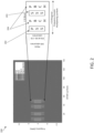
- FIG. 3 shows an example network architecture 300 include a gNB 301 and rotating UE 302. Whilst transmission from the gNB 301 may remain constant, received directional RSRP measurements at the UE 302 will change according to the angle of UE 302 relative to the gNB 301 as it rotates. Representations 303-306 reflect the changing angle of the user device as it is rotated.
- the disclosure provided herein uses just a few closed form equations (during a beam refinement procedure) to account for the device rotation during beam sweeping phase and adjusts the beam alignment outcome. This thereby produces a computationally efficient method of accounting for UE rotation.
- FIG. 4 shows, by way of example, a flowchart of a method 400 according to example embodiments. Each element of the flowchart may comprise one or more operations.
- the operations may be performed in hardware, software, firmware or a combination thereof.
- the operations may be performed, individually or collectively, by a means, wherein the means may comprise at least one processor; and at least one memory storing instructions that, when executed by the at least one processor, cause the performance of the operations.
- the method 400 is performed by an apparatus.
- the apparatus may be a user equipment according to the disclosure herein.
- the method 400 may comprise a first operation 401 of determining a first orientation of an apparatus at a first time instance.
- the first operation may comprise determining and storing the first orientation at the apparatus.
- the first orientation may be stored alongside the first time instance at which the first orientation was determined.
- the method 400 may comprise a second operation 402 of receiving, at substantially the first time instance, a reference signal from a network node. This may form part of the P1 procedure as the network node broadcast SSBs over a set of predefined directions and are received at the apparatus.
- the receipt of the reference signal from the network node may trigger the determination of the first orientation at the first time instance.
- the reference signal is received at exactly the same instance as the first orientation is determined, although it may be possible that the reference signal is received shortly before or after the determination of the first orientation.
- a measurement of a first orientation at a first time instance is associated with the received reference signal.
- the apparatus may already be synchronised with the network node such that it knows when to expect to receive the reference signal.
- the method 400 may comprises a third operation 403 of determining an RSRP value of the reference signal.
- the apparatus may measure and store the received RSRP for all the SSBs in SS burst. For each SSB or SS burst measurement period, the apparatus measures and stores the apparatus orientation. In this way, the first orientation is determined per a synchronization signal block, SSB, measurement or a synchronization signal burst, SS-burst, time instance.
- the method 400 may comprise a fourth operation 404 of determining a second orientation of the apparatus at a second time instance, wherein the second time instance is later than the first time instance. After a rotation of the apparatus the second orientation measurement can be taken. As such, the apparatus now knows the orientation of the apparatus both before and after a rotation of the apparatus.
- the method 400 may further comprise determining that a rotation of the apparatus has occurred.
- the apparatus may be triggered to determine the second orientation based on the determination that the apparatus has been rotated.
- the method 400 may further comprise a fifth operation 405 of determining a difference metric between the first orientation and second orientation.
- the difference metric may comprise a distance between the first orientation and the second orientation.
- the method 400 may further comprise a sixth operation 606 of, upon determining that the difference metric is greater than a predetermined threshold value, processing the RSRP, based on the difference metric, to provide a refined RSRP.
- the method 400 may further comprise commencing a wireless communication session with the network node, based on the refined RSRP value. For example, a beam may be selected from a UE codebook based on the refined RSRP value as the beam may be determined as an optimum beam.
- the apparatus calculates the distance between the device orientation at the first time instance with the device orientation at the second time instance. If the distance is above a threshold value (TH), the apparatus may initiate a beam measurement refinement procedure.
- the beam measurement refinement procedure includes processing the RSRP value determined in the third operation 403.
- the difference metric (and, by extension, distance metric) may optionally comprise a factor to account for angle wrapping.
- the angle wrapping factor may be different according to the co-ordinate system.
- FIG. 5 shows a block diagram of the process to determine whether the difference metric is greater than a predetermined threshold value and therefore whether to trigger the beam measurement refinement procedure.
- multiple device orientations are determined (e.g. the first orientation at the first time instance and the second orientation at the second time instance).
- the distance metric D ( n ) is calculated, for example, according to equations (1) or (2) above.
- a predetermined TH value is determined.
- the TH value may vary depending on system parameters and available computing resources. For example, if UE is in "low power mode", then the TH may be increased such that the beam refinement procedure is triggered less frequently. Also, if UE considers another beam codebook or different network node, the TH may change.
- step 504 it is determined whether the distance metric D ( n ) is greater than the predetermined TH. If the distance metric D ( n ) is greater than the predetermined TH for at least one reference signal (see step 505), then the beam measurement refinement procedure is triggered at step 506. Alternatively, the distance metric D ( n ) is not greater than the predetermined TH for any of the reference signals (see step 505) then the beam measurement refinement procedure is not triggered at step 507.
- FIG. 6 shows, by way of example, a flowchart of a method 600 according to example embodiments.
- the method 600 of FIG. 6 relates to the steps involved in a beam measurement refinement procedure.
- Each element of the flowchart may comprise one or more operations.
- the operations may be performed in hardware, software, firmware or a combination thereof.
- the operations may be performed, individually or collectively, by a means, wherein the means may comprise at least one processor; and at least one memory storing instructions that, when executed by the at least one processor, cause the performance of the operations.
- the method is performed by an apparatus.
- the apparatus may be a user equipment according to the disclosure herein.
- the method 600 may comprise a first to fourth operations i.e. 601-604 which correspond to the first to fourth operations shown in the method 400 of FIG. 4 .
- the method 600 may comprise a fifth operation 605 of mapping the RSRP value to a representation of the RSRP value in a directional space.
- the 'mapping' procedure is further discussed herein.
- the method 600 may comprise a sixth operation 606 of calculating a rotation angle of the apparatus.
- the rotation angle is calculated as a distance between the first orientation and the second orientation.
- the method 600 may comprise a seventh operation 607 of rotating the representation of the RSRP value by the rotation angle to produce a refined RSRP value.
- the rotation procedure for producing a refined RSRP value is further discussed herein.
- the method 600 optionally comprises obtaining a plurality of refined RSRP values for a plurality of reference signals and combining the plurality of refined RSRP values to produce an aggregated representation in the directional space.
- the method 600 optionally comprises determining an optimum user equipment, UE, beam from the aggregated representation.
- the optimum UE beam may be determined based on a strength associated with the aggregated representation in the directional space.
- the strength may be a strength associated with the refined RSRP values. As such, a beam associated with a highest refined RSRP value may be selected as the optimum UE beam.
- the method 600 optionally comprises commencing a wireless communication session with the network node, based on the optimum UE beam.
- the fifth operation 605 of method 600 comprises mapping a determined RSRP value to a representation of the RSRP value in a directional space.
- 'Mapping' may also herein be referred to as 'transforming'.
- a grid of discretized angles and directions can be used. For example, uniform sampling in azimuth and elevation angular space is a choice for definition of the grid of directions. Alternatively, a Fibonacci grid can be considered to guarantee uniform sampling in 3D sphere surrounding of a device. In hard, soft, hard-soft mapping solutions are proposed to obtain a representation of the measured beam RSRP.
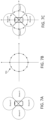
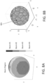
- FIGS. 7A-7C and 8A and 8B show examples of UE beam codebooks in 2D and 3D, definition of the direction grids.
- FIG. 7A shows a UE beam codebook with four beams (i.e. beam #1, beam #2, beam #3, beam #4) in 2-dimensions.
- FIG. 7B shows the discretized direction space with 12 segments 701 in the UE.
- FIG. 7C shows each beam represented by a set of directions in the direction grid.
- FIG. 8A shows beam-direction conversion in 3-dimensions (3D) for a beam region of a UE codebook with four beams in 3D.
- FIG. 8B shows mapping the UE beams to the 3D in the direction grid G. The number close to each point 801 shows the index of the beam that is mapped to.
- mapping procedure is as follow:
- R k , n G I k , n G ⁇ k , n G R n CB , where ⁇ k , n G is the normalization factor for the mapped directions to the n th beam.
- ⁇ k , n G 1 , ⁇ k, n.
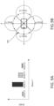
- the highest RSRP is measured by beam #2 and the lowest RSRP is measured by beam #1.
- device orientation during measurement time O (1) , O (2) , O (3) , O (4)
- beam #2 is selected as the optimal beam for communication.
- the RSRP measurements can be refined using the device orientation during measurement time ( O (1) , O (2) , O (3) , O (4) ) and a decisioning time (O (D) ).
- Each beam measurement is mapped to a representation in the direction space.
- the sixth operation 606 of method 600 comprises calculating a rotation angle of the apparatus.
- the rotation angle is calculated as a distance between the first orientation and the second orientation.
- the seventh operation 607 of method 600 comprises rotating the representation of the RSRP value by the rotation angle to produce a refined RSRP value.
- the representations in the mapped into the directional space are refined based on the device orientation during the measurement time.
- the refinement can be done by rotating the directions of the mapped representations based on the corresponding device orientation.
- FIGS. 10A-D show an example of the refined RSRP values for the four beams previously shown in FIGS. 9A and 9B .
- the RSRP values are based on the device orientation at the measurement time. In other words, the refined RSRP values are based on the device orientation at the first time instance O ( n ) and at the second time instance O ( D ) .
- the 3D rotation angles ( ⁇ ( n ) , ⁇ ( n ) , ⁇ ( n ) ) can be obtained to represent the device rotation between these two measurement times.
- the 3D rotation angles may correspond to a calculated distance between the first orientation and the second orientation.
- the k-th direction in the grid G can be represented with vector ⁇ k (as the Cartesian coordinates of the corresponding point on the unit sphere).
- FIGS. 10A-D show this refinement applied separately to each of beam #1, beam #2, beam #3, beam #4.
- the power of each of beam #1 to beam #4 is a shown in FIGS. 9A .
- the measured RSRP of beam #2 is the highest measured RSRP among the four measured RSRPs.
- the method 600 optionally comprises obtaining a plurality of refined RSRP values for a plurality of reference signals and combining the plurality of refined RSRP values to produce an aggregated representation in the directional space.
- FIG. 11A shows a simple aggregation method by merging all the refined RSRP values in a single representation.
- FIG. 11A shows a summation of the individual refined RSRP values shown in FIG. 10A-D .
- the refined RSRP values may not be aligned with the quantized directions in the direction grid. It is optional to quantize/transform the aggregated representation to a new representation aligned with a desired direction grid with Q directions (
- the method 600 optionally comprises determining an optimum user equipment, UE, beam from the aggregated representation.
- the optimum UE beam may be determined based on a strength associated with the aggregated representation in the directional space.
- the UE can assign and/or grant a value to RSRP of a beam.
- RSRP of a beam can be granted based on the average strength of RSRP values in each of the directions placed in the corresponding beam region as shown in FIG. 11B .
- the aggregated representations promote the selection of the optimum UE beam as beam #1 instead of beam #2. Even though beam #2 provided the highest RSRP during beam sweeping, but because the device is rotated, beam #1 should be used.
- a wireless communication session can be commenced with the network node, based on a selected optimum UE beam.
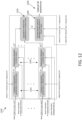
- FIG. 12 shows a block diagram of the process discussed herein for determining an optimum UE beam.
- RSRPs value are mapped (i.e. transformed) to a representations of the RSRP values in a directional space.
- refined RSRP values are determined by rotation based on a difference between apparatus orientation at different times.
- the plurality of refined RSRP values are aggregated to produce an aggregated representation in the directional space.
- an optimum UE beam is determined from the aggregated representation based on a strength associated with the aggregated representation in the directional space.
- an optimal UE beamformer is output.
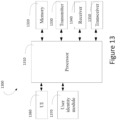
- FIG. 13 shows, by way of example, a block diagram of an apparatus capable of performing the method(s) as disclosed herein. Illustrated is device 1300, which may comprise, for example, a mobile communication device such as mobile 100 of FIG. 1 .
- processor 1310 which may comprise, for example, a single- or multi-core processor wherein a single-core processor comprises one processing core and a multi-core processor comprises more than one processing core.
- Processor 1310 may comprise, in general, a control device.
- Processor 1310 may comprise more than one processor.
- Processor 1310 may be a control device.
- a processing core may comprise, for example, a Cortex-A8 processing core manufactured by ARM Holdings or a Steamroller processing core designed by Advanced Micro Devices Corporation.
- Processor 1310 may comprise at least one Qualcomm Qualcomm Snapdragon and/or Intel Atom processor. Processor 1310 may comprise at least one application-specific integrated circuit, ASIC. Processor 1310 may comprise at least one field-programmable gate array, FPGA. Processor 1310 may be means for performing method steps in device 1300. Processor 1310 may be configured, at least in part by computer instructions, to perform actions.
- a processor may comprise circuitry, or be constituted as circuitry or circuitries, the circuitry or circuitries being configured to perform phases of methods in accordance with example embodiments described herein.
- circuitry may refer to one or more or all of the following: (a) hardware-only circuit implementations, such as implementations in only analog and/or digital circuitry, and (b) combinations of hardware circuits and software, such as, as applicable: (i) a combination of analog and/or digital hardware circuit(s) with software/firmware and (ii) any portions of hardware processor(s) with software (including digital signal processor(s)), software, and memory(ies) that work together to cause an apparatus, such as a mobile phone or a network node, to perform various functions) and (c) hardware circuit(s) and or processor(s), such as a microprocessor(s) or a portion of a microprocessor(s), that requires software (e.g., firmware) for operation, but the software may not be present when it is not needed for operation.
- firmware firmware
- circuitry also covers an implementation of merely a hardware circuit or processor (or multiple processors) or portion of a hardware circuit or processor and its (or their) accompanying software and/or firmware.
- circuitry also covers, for example and if applicable to the particular claim element, a baseband integrated circuit or processor integrated circuit for a mobile device or a similar integrated circuit in server, a cellular network device, or other computing or network device.
- Device 1300 may comprise memory 1320.
- Memory 1320 may comprise random-access memory and/or permanent memory.
- Memory 1320 may comprise at least one RAM chip.
- Memory 1320 may comprise solid-state, magnetic, optical and/or holographic memory, for example.
- Memory 1320 may be at least in part accessible to processor 1310.
- Memory 1320 may be at least in part comprised in processor 1310.
- Memory 1320 may be means for storing information.
- Memory 1320 may comprise computer instructions that processor 1310 is configured to execute. When computer instructions configured to cause processor 1310 to perform certain actions are stored in memory 1320, and device 1300 overall is configured to run under the direction of processor 1310 using computer instructions from memory 1320, processor 1310 and/or its at least one processing core may be considered to be configured to perform said certain actions.
- Memory 1320 may be at least in part external to device 1300 but accessible to device 1300.
- Device 1300 may comprise a transmitter 1330.
- Device 1300 may comprise a receiver 1340.
- Transmitter 1330 and receiver 1340 may be configured to transmit and receive, respectively, information in accordance with at least one cellular or non-cellular standard.
- Transmitter 1330 may comprise more than one transmitter.
- Receiver 1340 may comprise more than one receiver.
- Transmitter 1330 and/or receiver 1340 may be configured to operate in accordance with global system for mobile communication, GSM, wideband code division multiple access, WCDMA, 5G, long term evolution, LTE, IS-95, wireless local area network, WLAN, Ethernet and/or worldwide interoperability for microwave access, WiMAX, standards, for example.
- Device 1300 may comprise a near-field communication, NFC, transceiver 1350.
- NFC transceiver 1350 may support at least one NFC technology, such as NFC, Bluetooth, Wibree or similar technologies.
- Device 1300 may comprise user interface, UI, 1360.
- UI 1360 may comprise at least one of a display, a keyboard, a touchscreen, a vibrator arranged to signal to a user by causing device 1300 to vibrate, a speaker and a microphone.
- a user may be able to operate device 1300 via UI 1360, for example to accept incoming telephone calls, to originate telephone calls or video calls, to browse the Internet, to manage digital files stored in memory 1320 or on a cloud accessible via transmitter 1330 and receiver 1340, or via NFC transceiver 1350, and/or to play games.
- Device 1300 may comprise or be arranged to accept a user identity module 1370.
- User identity module 1370 may comprise, for example, a subscriber identity module, SIM, card installable in device 1300.
- a user identity module 1370 may comprise information identifying a subscription of a user of device 1300.
- a user identity module 1370 may comprise cryptographic information usable to verify the identity of a user of device 1300 and/or to facilitate encryption of communicated information and billing of the user of device 1300 for communication effected via device 1300.
- Processor 1310 may be furnished with a transmitter arranged to output information from processor 1310, via electrical leads internal to device 1300, to other devices comprised in device 1300.
- a transmitter may comprise a serial bus transmitter arranged to, for example, output information via at least one electrical lead to memory 1320 for storage therein.
- the transmitter may comprise a parallel bus transmitter.
- processor 1310 may comprise a receiver arranged to receive information in processor 1310, via electrical leads internal to device 1300, from other devices comprised in device 1300.
- Such a receiver may comprise a serial bus receiver arranged to, for example, receive information via at least one electrical lead from receiver 1340 for processing in processor 1310.
- the receiver may comprise a parallel bus receiver.
- Processor 1310, memory 1320, transmitter 1330, receiver 1340, NFC transceiver 1350, UI 1360 and/or user identity module 1370 may be interconnected by electrical leads internal to device 1300 in a multitude of different ways.
- each of the aforementioned devices may be separately connected to a master bus internal to device 1300, to allow for the devices to exchange information.
- this is only one example and depending on the embodiment various ways of interconnecting at least two of the aforementioned devices may be selected.
- each of the entities described in the present description may be based on a different hardware, or some or all of the entities may be based on the same hardware. It does not necessarily mean that they are based on different software. That is, each of the entities described in the present description may be based on different software, or some or all of the entities may be based on the same software.
- Each of the entities described in the present description may be embodied in the cloud.
- Implementations of any of the above described blocks, apparatuses, systems, techniques or methods include, as non-limiting examples, implementations as hardware, software, firmware, special purpose circuits or logic, general purpose hardware or controller or other computing devices, or some combination thereof. Some embodiments may be implemented in the cloud.
Landscapes
- Engineering & Computer Science (AREA)
- Computer Networks & Wireless Communication (AREA)
- Signal Processing (AREA)
- Quality & Reliability (AREA)
- Physics & Mathematics (AREA)
- Electromagnetism (AREA)
- Mobile Radio Communication Systems (AREA)
- Small-Scale Networks (AREA)
Applications Claiming Priority (1)
| Application Number | Priority Date | Filing Date | Title |
|---|---|---|---|
| GB2318106.8A GB2636083A (en) | 2023-11-28 | 2023-11-28 | Beam management |
Publications (1)
| Publication Number | Publication Date |
|---|---|
| EP4564700A1 true EP4564700A1 (fr) | 2025-06-04 |
Family
ID=89429074
Family Applications (1)
| Application Number | Title | Priority Date | Filing Date |
|---|---|---|---|
| EP24200247.5A Pending EP4564700A1 (fr) | 2023-11-28 | 2024-09-13 | Gestion de faisceau |
Country Status (3)
| Country | Link |
|---|---|
| US (1) | US20250175267A1 (fr) |
| EP (1) | EP4564700A1 (fr) |
| GB (1) | GB2636083A (fr) |
Citations (1)
| Publication number | Priority date | Publication date | Assignee | Title |
|---|---|---|---|---|
| US20230042556A1 (en) * | 2021-08-06 | 2023-02-09 | Samsung Electronics Co., Ltd. | Method and apparatus of beam management with measurement aging |
Family Cites Families (4)
| Publication number | Priority date | Publication date | Assignee | Title |
|---|---|---|---|---|
| KR102547397B1 (ko) * | 2018-08-31 | 2023-06-26 | 삼성전자 주식회사 | 무선 통신 시스템에서 빔을 형성하는 방법 및 전자 장치 |
| US12126420B2 (en) * | 2019-09-20 | 2024-10-22 | Nokia Technologies Oy | Beam alignment verification for wireless networks |
| CN114828107B (zh) * | 2021-01-21 | 2025-05-27 | 联发科技股份有限公司 | 用于测量和用户设备天线选择的方法 |
| US12289745B2 (en) * | 2021-08-11 | 2025-04-29 | Qualcomm Incorporated | User equipment extended reality information-based beam management |
-
2023
- 2023-11-28 GB GB2318106.8A patent/GB2636083A/en active Pending
-
2024
- 2024-09-13 EP EP24200247.5A patent/EP4564700A1/fr active Pending
- 2024-11-21 US US18/955,084 patent/US20250175267A1/en active Pending
Patent Citations (1)
| Publication number | Priority date | Publication date | Assignee | Title |
|---|---|---|---|---|
| US20230042556A1 (en) * | 2021-08-06 | 2023-02-09 | Samsung Electronics Co., Ltd. | Method and apparatus of beam management with measurement aging |
Also Published As
| Publication number | Publication date |
|---|---|
| US20250175267A1 (en) | 2025-05-29 |
| GB202318106D0 (en) | 2024-01-10 |
| GB2636083A (en) | 2025-06-11 |
Similar Documents
| Publication | Publication Date | Title |
|---|---|---|
| US20200336194A1 (en) | Joint beam reporting for wireless networks | |
| EP3868034B1 (fr) | Optimisation de formeur de faisceaux basée sur la probabilité de position | |
| US12432675B2 (en) | Signal synchronization for over-the-air aggregation in a federated learning framework | |
| JP2020504917A (ja) | コードブック制限を含む、ビームフォーミング手順において使用するためのミリメートル波長ネットワークマップ | |
| EP4309438B1 (fr) | Rétroaction en boucle fermée pour positionnement amélioré | |
| WO2021032300A1 (fr) | Appareil, procédé et programme informatique permettant de déterminer une direction de formation de faisceau | |
| WO2023172804A1 (fr) | Systèmes et techniques de signalisation sécurisée de positionnement | |
| US12506521B2 (en) | Method for data augmentation for channel state information feedback | |
| EP4038759B1 (fr) | Procédé et dispositif de réseau destinés à une sélection de vecteur de faisceau | |
| EP4315986A1 (fr) | Changement conditionnel d'une cellule primaire d'un groupe de cellules secondaire | |
| KR20240064645A (ko) | 의사 코로케이션 정보를 사용한 최적화된 빔 선택 | |
| US20250175267A1 (en) | Beam management | |
| WO2024240380A1 (fr) | Activation d'états d'indicateur de configuration de transmission (tci) | |
| CN112994766A (zh) | 一种波束传输方法及相关设备 | |
| WO2023209272A1 (fr) | Rapport de mesure amélioré pour un équipement utilisateur | |
| US12550085B2 (en) | Timing advance loops | |
| WO2023117077A1 (fr) | Sélection de ressources radio en fonction de la direction pour une communication directe entre des dispositifs sans fil | |
| EP4366181A1 (fr) | Alignement de faisceau | |
| CN120390219B (zh) | 一种通信方法及相关设备 | |
| US12314826B1 (en) | Secondary cell selection | |
| EP4564701A1 (fr) | Procédé de mesure et de rapport améliorés | |
| WO2025111919A1 (fr) | Amélioration de catégorisation de gestion de ressources radio pour réalité étendue | |
| WO2025081505A1 (fr) | Dispositifs et procédés de communication | |
| US20230269678A1 (en) | Beam source assistance information | |
| US20250039837A1 (en) | Apparatus, methods, and computer programs |
Legal Events
| Date | Code | Title | Description |
|---|---|---|---|
| PUAI | Public reference made under article 153(3) epc to a published international application that has entered the european phase |
Free format text: ORIGINAL CODE: 0009012 |
|
| STAA | Information on the status of an ep patent application or granted ep patent |
Free format text: STATUS: THE APPLICATION HAS BEEN PUBLISHED |
|
| AK | Designated contracting states |
Kind code of ref document: A1 Designated state(s): AL AT BE BG CH CY CZ DE DK EE ES FI FR GB GR HR HU IE IS IT LI LT LU LV MC ME MK MT NL NO PL PT RO RS SE SI SK SM TR |
|
| STAA | Information on the status of an ep patent application or granted ep patent |
Free format text: STATUS: REQUEST FOR EXAMINATION WAS MADE |
|
| 17P | Request for examination filed |
Effective date: 20251009 |