EP4564791A1 - Verrouillage d'un couvercle de batterie pour un appareil électronique - Google Patents
Verrouillage d'un couvercle de batterie pour un appareil électronique Download PDFInfo
- Publication number
- EP4564791A1 EP4564791A1 EP24210903.1A EP24210903A EP4564791A1 EP 4564791 A1 EP4564791 A1 EP 4564791A1 EP 24210903 A EP24210903 A EP 24210903A EP 4564791 A1 EP4564791 A1 EP 4564791A1
- Authority
- EP
- European Patent Office
- Prior art keywords
- region
- cover
- engaging
- casing
- finger
- Prior art date
- Legal status (The legal status is an assumption and is not a legal conclusion. Google has not performed a legal analysis and makes no representation as to the accuracy of the status listed.)
- Pending
Links
Images


Classifications
-
- H—ELECTRICITY
- H04—ELECTRIC COMMUNICATION TECHNIQUE
- H04M—TELEPHONIC COMMUNICATION
- H04M1/00—Substation equipment, e.g. for use by subscribers
- H04M1/02—Constructional features of telephone sets
- H04M1/0202—Portable telephone sets, e.g. cordless phones, mobile phones or bar type handsets
- H04M1/026—Details of the structure or mounting of specific components
- H04M1/0262—Details of the structure or mounting of specific components for a battery compartment
-
- H—ELECTRICITY
- H01—ELECTRIC ELEMENTS
- H01M—PROCESSES OR MEANS, e.g. BATTERIES, FOR THE DIRECT CONVERSION OF CHEMICAL ENERGY INTO ELECTRICAL ENERGY
- H01M50/00—Constructional details or processes of manufacture of the non-active parts of electrochemical cells other than fuel cells, e.g. hybrid cells
- H01M50/20—Mountings; Secondary casings or frames; Racks, modules or packs; Suspension devices; Shock absorbers; Transport or carrying devices; Holders
- H01M50/271—Lids or covers for the racks or secondary casings
-
- Y—GENERAL TAGGING OF NEW TECHNOLOGICAL DEVELOPMENTS; GENERAL TAGGING OF CROSS-SECTIONAL TECHNOLOGIES SPANNING OVER SEVERAL SECTIONS OF THE IPC; TECHNICAL SUBJECTS COVERED BY FORMER USPC CROSS-REFERENCE ART COLLECTIONS [XRACs] AND DIGESTS
- Y02—TECHNOLOGIES OR APPLICATIONS FOR MITIGATION OR ADAPTATION AGAINST CLIMATE CHANGE
- Y02E—REDUCTION OF GREENHOUSE GAS [GHG] EMISSIONS, RELATED TO ENERGY GENERATION, TRANSMISSION OR DISTRIBUTION
- Y02E60/00—Enabling technologies; Technologies with a potential or indirect contribution to GHG emissions mitigation
- Y02E60/10—Energy storage using batteries
Definitions
- the present disclosure relates to a cover piece detachably attached to an opening of a casing and an electronic device.
- a cover for covering the battery compartment has (i) an engagement projection to engage with the opening of the casing at one end and (ii) a U-shaped elastic piece (plate spring), a protrusion to engage with the opening, and a groove at the other end. With the protrusion and the groove, the cover is detachably engaged with the opening of the casing.
- the region of the elastic piece needs to be as compact as possible.
- the movable range of a finger-putting part is made narrow, on which a finger is put to deform the elastic piece to detach the battery cover. According to such a structure, the battery cover may not be easily disengaged even if the finger-putting part is sufficiently moved.
- An object of the present disclosure is to ensure the capacity of the opening of the casing as well as to ensure disengagement of the cover.
- a cover piece for covering an opening of a casing by being engaged with an engaging target part formed on the opening, the cover piece including an elastic member, wherein a first region and a second region are integrally formed with the elastic member, the first region including an engaging part and a finger-putting part, the second region being formed at a position to face the first region; the engaging part engaged with the engaging target part is disengaged from the engaging target part in response to the finger-putting part being moved in a direction of bringing the first region toward the second region; and at least either an edge of a corner region of the first region facing the second region or an edge of a corner region of the second region facing the first region is removed.
- the capacity of the opening of the casing can be secured, and disengagement of the cover can be ensured.
- a scientific calculator is used as an example of an electronic device to which the present disclosure is applied.
- the electronic device is not limited to a scientific calculator.
- the present disclosure is applicable to any electronic device (e.g., an electronic dictionary or a tablet terminal) that is provided with a cover 20 configured to cover an opening 11 of a casing 10, which are described later.
- the scientific calculator 1 includes a casing 10 and a cover (cover body) 20.
- FIG. 1 shows the top-bottom direction, the left-right direction, and the front-back direction that are perpendicular to each other.
- the front-back direction corresponds to the thickness direction of the casing 10.
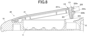
- an opening 11 is formed to house (load) not-illustrated four dry cell batteries or not-illustrated dry-cell-type secondary batteries (see FIG.5 and FIG.8 ).
- the opening 11 has a round shape corresponding to the external round shape of the cover 20 (see FIG.3 ). By attaching the cover 20, the opening 11 is covered.
- an engaging target part (engaging target region) 12 is provided at a specific position of the opening 11 corresponding to a hook 22 (described later) of the cover 20.
- the engaging target part 12 is engaged with the hook 22 when the cover 20 is attached.
- the engaging target part 12 is formed like an eave that projects from the edge of the opening 11 toward the center of the opening 11 while sloping downward. As shown in FIG.7 , the engaging target part 12 includes an engaging target surface 121. The engaging target surface 121 is formed to be engaged with an engaging surface 222c1 of each rib 222c formed on the hook 22. The ribs 222c are described later. The engaging target part 12 has a sloping surface 122 (first surface) adjacent to the engaging target surface 121.
- the sloping surface 122 faces the sloping surfaces 222c2 (second surface) of the ribs 222c with a predetermined distance from the sloping surfaces 222c2.
- the predetermined distance is determined so as to prevent rattling, which is caused by an impact on the cover 20 or the casing 10.
- rattling caused by an impact on the cover 20 or the casing 10 can be appropriately prevented.
- locking holes are formed although not illustrated.
- the locking parts 23 are locked (inserted) to the locking holes when the cover 20 is attached.
- the cover 20 includes a cover body 21, the hook 22 (elastic member), and the locking parts 23.
- the cover body 21 is for covering the opening 11 of the casing 10.
- the cover body 21 has a round shape (disk shape) corresponding to the round-shaped opening 11. Part of the cover body 21 corresponding to the engaging target part 12 of the casing 10 is notched.
- the hook 22 is formed at the inner end 21a of the notch.
- the hook 22 is formed to engage the cover 20 with the casing 10.
- the hook 22 is a plate spring hook and includes a base part 221 (second region), a manipulation part 222 (first region), and a connecting part 223.
- the base part 221 protrudes substantially in the thickness direction of the casing 10 from the back surface side of the end 21a of the cover body 21.
- the direction in which the base part 221 protrudes may not be identical to the thickness direction.
- the back surface side of the cover 20 is the side that faces the casing 10 when the cover 20 is attached to the casing 10.
- the manipulation part 222 is formed to face the base part 221.
- the connecting part 223 connects the base part 221 and the manipulation part 222.
- the hook 22 When the cover 20 is attached to the casing 10, the hook 22 is biased toward the engaging target part 12.
- the hook 22 is not limited to a plate spring hook as long as the hook 22 is biased toward the engaging target part 12 when the cover 20 is attached to the casing 10.
- the hook 22 may be a hook using other biasing means, such as a coil spring or a rubber.
- the manipulation part 222 includes a finger-putting part (finger-putting region) 222a. In removing the cover 20 from the casing 10, the finger-putting part 222a is moved in the direction of loosening the engagement between the casing 10 and the cover 20 (in the direction from top to bottom in FIG.1 ) .
- the finger-putting part 222a has a hook shape and is formed at the free end of the manipulation part 222 opposite the end connected to the connecting part 223.
- the finger-putting part 222a has a curved shape that is depressed in the direction of loosening the engagement between the casing 10 and the cover 20 (in the direction from top to bottom in FIG.1 ). That is, the finger-putting part 222a is depressed in the direction opposite the arc-shaped depression of the part of the opening 11 corresponding to the finger-putting part 222a, the part of the opening 11 being provided with the engaging target part 12.
- the finger-putting part 222a is formed not to protrude from the outer surface of the casing 10 when the cover 20 covers the casing 10.
- the finger-putting part 222a has a crook-shaped corner C1.
- the corner C1 is rounded (the sharp edge of the corner C1 is removed).
- the manipulation part 222 has an engaging part (engaging region) 222b between one end connected to the connecting part 223 and the other end having the finger-putting part 222a.
- the engaging part 222b is formed to be engaged with the engaging target part 12 formed on the casing 10. As shown in FIG.5 and FIG.6A , the upper surface of the engaging part 222b slopes downward toward the engaging target part 12. On the upper surface of the engaging part 222b, ribs 222c are formed.
- each rib 222c has an engaging surface 222c1 and a sloping surface 222c2 adjacent to the lower end of the engaging surface 222c1.
- the engaging surface 222c1 is formed to be engaged with the engaging target surface 121 of the engaging target part 12 of the casing 10.
- the manipulation part 222 is pushed toward the base part 221 by the engaging target part 12. That is, when the cover 20 is attached to the casing 10, the manipulation part 222 (hook 22) is biased toward the engaging target part 12.
- the ribs 222c prevent rattling and serve to determine the position of the cover 20 in the height direction (the thickness direction of the casing 10).
- the sloping surface 222c2 slopes downward toward the engaging target part 12, as shown in FIG.7 .
- the engaging surfaces 222c1 are engaged with the engaging target surface 121, namely when the cover 20 is attached to the casing 10, the sloping surfaces 222c2 face the sloping surface 122 of the engaging target part 12 with a predetermined distance from the sloping surface 122.
- the connecting part 223 connects the base part 221 and the manipulation part 222, as described above.
- the connecting part 223 is U-shaped when viewed from the lateral side.
- the manipulation part 222 which includes the engaging part 222b, is swingable in the direction of separating from the engaging target part 12 (toward the base part 221) or in the direction toward the engaging target part 12 (separating from the base part 221) on the lowest end of the connecting part 223 as the center.
- the axis is the center of the connecting part 223 in the width direction of the connecting part 223.
- the base part 221, the manipulation part 222, the engaging part 222b, and the connecting part 223 of the hook 22 have the curved shape depressed in the direction of loosening the engagement between the casing 10 and the cover 20 so as to correspond to the curved shape of the finger-putting part 222a (see FIG. 3 ).
- the finger-putting part 222a is moved in the direction of loosening the engagement between the casing 10 and the cover 20 to detach the cover 20 from the casing 10, stress tends to concentrate on both ends of the connecting part 223 in the width direction.
- chamfered parts 223a are formed on both ends of the connecting part 223 in the width direction. That is, both ends of the connecting part 223 in the width direction (in the left-right direction in FIG.1 ) are cut off. This reduces the concentration of stress on both ends of the connecting part 223 in the width direction.
- the base part 221 protrudes from the back surface side of the inner end 21a of the cover body 21, as described above. As shown in FIG.5 and FIG.6A , the base part 221 has a chamfered part 221a at an L-shaped corner C2, which is formed by the base part 221 and the cover body 21.
- the chamfered part 221a is formed at a part of the base part 221 that abuts the corner C1 of the finger-putting part 222a when the finger-putting part 222a is moved in the direction of loosening the engagement between the casing 10 and the cover 20.
- the chamfered part 221a is formed at an angle (relief angle) corresponding to the leaning angle of the manipulation part 222 when the finger-putting part 222a abuts the base part 221.
- the chamfered part 221a is formed with a relief shape at a relief angle.
- the relief angle corresponds to the angle of the manipulation part 222 in contact with (abutting) the base part 221 when the finger-putting part 222a is moved in the direction of bringing the manipulation part 222 toward the base part 221.
- FIG.6B shows the state where the finger-putting part 222a is moved from the state of FIG.6A in the direction of bringing the manipulation part 222 toward the base part 221.
- the chamfered part 221a is at a position where the manipulation part 222 abuts the base part 221, and the chamfered part 221a is at an angle corresponding to the leaning angle of the manipulation part 222 abutting the base part 221.
- the corner C1 of the finger-putting part 222a is rounded, and the chamfered part 221a is formed on the base part 221.
- Such a structure increases the stroke amount (moving amount) of the finger-putting part 222a even if there is not enough moving distance.
- the engagement between the casing 10 and the cover 20 is certainly released when the finger-putting part 222a is moved in the direction of loosening the engagement between the casing 10 and the cover 20.
- the rounded corner may be formed on the corner C2
- the chamfered part 221a may be formed on the manipulation part 222.
- the locking parts 23 are inserted into the not-illustrated locking holes formed in the opening 11, thereby being engaged with the locking holes.
- Two locking parts 23 are formed on the edge of the cover body 21. Specifically, the locking parts 23 are formed on the edge of the cover body 21 such that the locking parts 23 and the hook 22 form an isosceles triangle.
- the cover 20 is supported by the hook 22 and the two locking parts 23.
- the cover body 21, the hook 22, and the locking parts 23 are formed as one body.
- the scientific calculator 1 includes the cover 20 for covering the opening 11 of the casing 10 by being engaged with the engaging target part 12 (engaging target region) formed on the opening 11.
- the cover 20 includes the hook 22 (elastic member) .
- the manipulation part 222 first region
- the base part 221 second region
- the manipulation part 222 includes the engaging part 222b (engaging region) and the finger-putting part 222a (finger-putting region).
- the base part 221 is formed at a position to face the manipulation part 222.
- the engaging part 222b engaged with the engaging target part 12 is disengaged from the engaging target part 12 when the finger-putting part 222a is moved in a direction of bringing the manipulation part 222 toward the base part 221. At least either the edge of the corner C1 of the manipulation part 222 that faces the base part 221 or the edge of the corner C2 of the base part 221 that faces the manipulation part 222 is removed.
- the corner C1 of the manipulation part 222 can be prevented from contacting (abutting) the corner C2 of the base part 221 when the finger-putting part 222a is moved in the direction of loosening the engagement between the casing 10 and the cover 20.
- Such a structure allows the finger-putting part 222a to have a greater stroke amount (moving amount), so that the engagement between the casing 10 and the cover 20 can be certainly released when the finger-putting part 222a is moved in the direction of loosening the engagement.
- the finger-putting part 222a has a greater stroke amount, the area of the opening 11 corresponding to the hook 22 does not need to be widened, and the capacity of the opening 11 of the casing 10 (the capacity of the battery housing space) is easily secured.
- a relief shape (chamfered part 221a) is formed at a relief angle, the relief angle corresponding to an angle at which the manipulation part 222 is in contact with the base part 221 when the finger-putting part 222a is moved in the direction of bringing the manipulation part 222 toward the base part 221.
- the corner C1 of the manipulation part 222 is further prevented from contacting (abutting) the corner C2 of the base part 221.
- the opening 11 of the casing 10 has a round shape in the above embodiment, the opening 11 is not limited to a round shape.
- the opening 11 may have a rectangular or oval shape, for example. If the opening 11 is rectangular, the cover body 21 has a shape corresponding to the rectangular opening 11.
- the corner C1 of the finger-putting part 222a is rounded, and the chamfered part 221a is formed on the base part 221.
- the base part 221 may not have the chamfered part 221a, for example.
- the corner C1 of the finger-putting part 222a may not be rounded.
- the locking parts 23 of the cover 20 are fitted into not-illustrated locking holes formed at predetermined positions of the opening 11.
- the cover 20 may be coupled to the casing 10 by a hinge that allows opening and closing of the opening 11, for example. In this case, the cover 20 is not completely detached from the casing 10.
- the shape of the curved surface of the sloping surface 222c2 may be matched to the shape of the movement locus of the sloping surface 222c2 when the engaging part 222b of the lid member 10 is swung.
- Such a structure prevents the cover 20 from moving upward by the impact on the cover 20 or the casing 10, thereby preventing the detachment of the cover 20 from the casing 10.
- Such a structure also allows proper disengagement of the cover 20 from the casing 10.
Landscapes
- Chemical & Material Sciences (AREA)
- Chemical Kinetics & Catalysis (AREA)
- Electrochemistry (AREA)
- General Chemical & Material Sciences (AREA)
- Engineering & Computer Science (AREA)
- Signal Processing (AREA)
- Battery Mounting, Suspending (AREA)
- Casings For Electric Apparatus (AREA)
Applications Claiming Priority (1)
| Application Number | Priority Date | Filing Date | Title |
|---|---|---|---|
| JP2023202708A JP2025088177A (ja) | 2023-11-30 | 2023-11-30 | 筐体の開口部と蓋体との係合構造 |
Publications (1)
| Publication Number | Publication Date |
|---|---|
| EP4564791A1 true EP4564791A1 (fr) | 2025-06-04 |
Family
ID=93430414
Family Applications (1)
| Application Number | Title | Priority Date | Filing Date |
|---|---|---|---|
| EP24210903.1A Pending EP4564791A1 (fr) | 2023-11-30 | 2024-11-05 | Verrouillage d'un couvercle de batterie pour un appareil électronique |
Country Status (2)
| Country | Link |
|---|---|
| EP (1) | EP4564791A1 (fr) |
| JP (1) | JP2025088177A (fr) |
Citations (4)
| Publication number | Priority date | Publication date | Assignee | Title |
|---|---|---|---|---|
| JPS5775478U (fr) | 1980-10-27 | 1982-05-10 | ||
| GB2352003A (en) * | 1999-07-13 | 2001-01-17 | Motorola Inc | Plastics and metal integrated latch |
| KR20060074294A (ko) * | 2004-12-27 | 2006-07-03 | 주식회사 팬택 | 휴대용 단말기의 배터리 고정 장치 |
| US20090243910A1 (en) * | 2008-03-31 | 2009-10-01 | Panasonic Corporation | Remote controller |
-
2023
- 2023-11-30 JP JP2023202708A patent/JP2025088177A/ja active Pending
-
2024
- 2024-11-05 EP EP24210903.1A patent/EP4564791A1/fr active Pending
Patent Citations (4)
| Publication number | Priority date | Publication date | Assignee | Title |
|---|---|---|---|---|
| JPS5775478U (fr) | 1980-10-27 | 1982-05-10 | ||
| GB2352003A (en) * | 1999-07-13 | 2001-01-17 | Motorola Inc | Plastics and metal integrated latch |
| KR20060074294A (ko) * | 2004-12-27 | 2006-07-03 | 주식회사 팬택 | 휴대용 단말기의 배터리 고정 장치 |
| US20090243910A1 (en) * | 2008-03-31 | 2009-10-01 | Panasonic Corporation | Remote controller |
Also Published As
| Publication number | Publication date |
|---|---|
| JP2025088177A (ja) | 2025-06-11 |
Similar Documents
| Publication | Publication Date | Title |
|---|---|---|
| EP0307892B1 (fr) | Boîtier portatif comprenant une poignée pivotante | |
| US6373706B1 (en) | Electronic device having two slots different in width | |
| KR100225161B1 (ko) | 표면접점부착 카드용 커넥터 | |
| US8361643B2 (en) | Battery cover latch mechanism and portable electronic device using same | |
| JP2785750B2 (ja) | 電子機器カバーのロック構造 | |
| US7700223B2 (en) | Battery cover assembly for portable electronic device | |
| CA2163604C (fr) | Boitier pour element electronique, comportant un espace de rangement | |
| US20100130268A1 (en) | Battery cover latch mechanism and portable electronic device using same | |
| JP5027449B2 (ja) | 電子機器カバーのロック構造 | |
| US8481200B2 (en) | Battery cover | |
| US5135822A (en) | Battery housing structure | |
| EP4564791A1 (fr) | Verrouillage d'un couvercle de batterie pour un appareil électronique | |
| JPH11274751A (ja) | 小型電子機器の着脱装置 | |
| EP4567553A1 (fr) | Couvercle et dispositif électronique | |
| EP4571455A1 (fr) | Structure et dispositif de maintien de couvercle | |
| US7542278B2 (en) | Electronic apparatus incorporating fixing mechanism | |
| US11733738B2 (en) | Electronic device | |
| CN101515637B (zh) | 电池、充电设备及电子设备 | |
| JP2013110642A (ja) | 携帯端末 | |
| JP4539357B2 (ja) | バッテリ、充電装置及び電子装置 | |
| JP2003036921A (ja) | シャッタ付きコネクタ | |
| JP4752277B2 (ja) | 電子機器における電池のロック構造 | |
| JP2004221121A (ja) | フック取付構造およびこのフック取付構造を用いた筐体構造 | |
| JPH08167403A (ja) | 電池収納構造 | |
| EP4227766A1 (fr) | Dispositif de remplacement et dispositif électronique |
Legal Events
| Date | Code | Title | Description |
|---|---|---|---|
| PUAI | Public reference made under article 153(3) epc to a published international application that has entered the european phase |
Free format text: ORIGINAL CODE: 0009012 |
|
| STAA | Information on the status of an ep patent application or granted ep patent |
Free format text: STATUS: REQUEST FOR EXAMINATION WAS MADE |
|
| 17P | Request for examination filed |
Effective date: 20241105 |
|
| AK | Designated contracting states |
Kind code of ref document: A1 Designated state(s): AL AT BE BG CH CY CZ DE DK EE ES FI FR GB GR HR HU IE IS IT LI LT LU LV MC ME MK MT NL NO PL PT RO RS SE SI SK SM TR |
|
| GRAP | Despatch of communication of intention to grant a patent |
Free format text: ORIGINAL CODE: EPIDOSNIGR1 |
|
| STAA | Information on the status of an ep patent application or granted ep patent |
Free format text: STATUS: GRANT OF PATENT IS INTENDED |