EP4564846A1 - Ensemble récepteur avec passage acoustique arrière pour un dispositif pouvant être porté sur l'oreille - Google Patents
Ensemble récepteur avec passage acoustique arrière pour un dispositif pouvant être porté sur l'oreille Download PDFInfo
- Publication number
- EP4564846A1 EP4564846A1 EP24175764.0A EP24175764A EP4564846A1 EP 4564846 A1 EP4564846 A1 EP 4564846A1 EP 24175764 A EP24175764 A EP 24175764A EP 4564846 A1 EP4564846 A1 EP 4564846A1
- Authority
- EP
- European Patent Office
- Prior art keywords
- receiver
- ear
- acoustic
- housing
- wearable device
- Prior art date
- Legal status (The legal status is an assumption and is not a legal conclusion. Google has not performed a legal analysis and makes no representation as to the accuracy of the status listed.)
- Withdrawn
Links
Images




Classifications
-
- H—ELECTRICITY
- H04—ELECTRIC COMMUNICATION TECHNIQUE
- H04R—LOUDSPEAKERS, MICROPHONES, GRAMOPHONE PICK-UPS OR LIKE ACOUSTIC ELECTROMECHANICAL TRANSDUCERS; ELECTRIC HEARING AIDS; PUBLIC ADDRESS SYSTEMS
- H04R1/00—Details of transducers, loudspeakers or microphones
- H04R1/10—Earpieces; Attachments therefor ; Earphones; Monophonic headphones
- H04R1/1016—Earpieces of the intra-aural type
-
- H—ELECTRICITY
- H04—ELECTRIC COMMUNICATION TECHNIQUE
- H04R—LOUDSPEAKERS, MICROPHONES, GRAMOPHONE PICK-UPS OR LIKE ACOUSTIC ELECTROMECHANICAL TRANSDUCERS; ELECTRIC HEARING AIDS; PUBLIC ADDRESS SYSTEMS
- H04R1/00—Details of transducers, loudspeakers or microphones
- H04R1/10—Earpieces; Attachments therefor ; Earphones; Monophonic headphones
- H04R1/1058—Manufacture or assembly
-
- H—ELECTRICITY
- H04—ELECTRIC COMMUNICATION TECHNIQUE
- H04R—LOUDSPEAKERS, MICROPHONES, GRAMOPHONE PICK-UPS OR LIKE ACOUSTIC ELECTROMECHANICAL TRANSDUCERS; ELECTRIC HEARING AIDS; PUBLIC ADDRESS SYSTEMS
- H04R1/00—Details of transducers, loudspeakers or microphones
- H04R1/20—Arrangements for obtaining desired frequency or directional characteristics
- H04R1/22—Arrangements for obtaining desired frequency or directional characteristics for obtaining desired frequency characteristic only
- H04R1/28—Transducer mountings or enclosures modified by provision of mechanical or acoustic impedances, e.g. resonator, damping means
- H04R1/2807—Enclosures comprising vibrating or resonating arrangements
- H04R1/2811—Enclosures comprising vibrating or resonating arrangements for loudspeaker transducers
-
- H—ELECTRICITY
- H04—ELECTRIC COMMUNICATION TECHNIQUE
- H04R—LOUDSPEAKERS, MICROPHONES, GRAMOPHONE PICK-UPS OR LIKE ACOUSTIC ELECTROMECHANICAL TRANSDUCERS; ELECTRIC HEARING AIDS; PUBLIC ADDRESS SYSTEMS
- H04R1/00—Details of transducers, loudspeakers or microphones
- H04R1/10—Earpieces; Attachments therefor ; Earphones; Monophonic headphones
- H04R1/1058—Manufacture or assembly
- H04R1/1075—Mountings of transducers in earphones or headphones
-
- H—ELECTRICITY
- H04—ELECTRIC COMMUNICATION TECHNIQUE
- H04R—LOUDSPEAKERS, MICROPHONES, GRAMOPHONE PICK-UPS OR LIKE ACOUSTIC ELECTROMECHANICAL TRANSDUCERS; ELECTRIC HEARING AIDS; PUBLIC ADDRESS SYSTEMS
- H04R1/00—Details of transducers, loudspeakers or microphones
- H04R1/20—Arrangements for obtaining desired frequency or directional characteristics
- H04R1/22—Arrangements for obtaining desired frequency or directional characteristics for obtaining desired frequency characteristic only
- H04R1/28—Transducer mountings or enclosures modified by provision of mechanical or acoustic impedances, e.g. resonator, damping means
- H04R1/2807—Enclosures comprising vibrating or resonating arrangements
- H04R1/2815—Enclosures comprising vibrating or resonating arrangements of the bass reflex type
- H04R1/2819—Enclosures comprising vibrating or resonating arrangements of the bass reflex type for loudspeaker transducers
-
- H—ELECTRICITY
- H04—ELECTRIC COMMUNICATION TECHNIQUE
- H04R—LOUDSPEAKERS, MICROPHONES, GRAMOPHONE PICK-UPS OR LIKE ACOUSTIC ELECTROMECHANICAL TRANSDUCERS; ELECTRIC HEARING AIDS; PUBLIC ADDRESS SYSTEMS
- H04R1/00—Details of transducers, loudspeakers or microphones
- H04R1/20—Arrangements for obtaining desired frequency or directional characteristics
- H04R1/22—Arrangements for obtaining desired frequency or directional characteristics for obtaining desired frequency characteristic only
- H04R1/28—Transducer mountings or enclosures modified by provision of mechanical or acoustic impedances, e.g. resonator, damping means
- H04R1/2807—Enclosures comprising vibrating or resonating arrangements
- H04R1/2815—Enclosures comprising vibrating or resonating arrangements of the bass reflex type
- H04R1/2823—Vents, i.e. ports, e.g. shape thereof or tuning thereof with damping material
-
- H—ELECTRICITY
- H04—ELECTRIC COMMUNICATION TECHNIQUE
- H04R—LOUDSPEAKERS, MICROPHONES, GRAMOPHONE PICK-UPS OR LIKE ACOUSTIC ELECTROMECHANICAL TRANSDUCERS; ELECTRIC HEARING AIDS; PUBLIC ADDRESS SYSTEMS
- H04R2460/00—Details of hearing devices, i.e. of ear- or headphones covered by H04R1/10 or H04R5/033 but not provided for in any of their subgroups, or of hearing aids covered by H04R25/00 but not provided for in any of its subgroups
- H04R2460/11—Aspects relating to vents, e.g. shape, orientation, acoustic properties in ear tips of hearing devices to prevent occlusion
Definitions
- Embodiments herein relate to ear-wearable devices and more particularly to ear-wearable devices having moving coil receivers.
- Ear-wearable devices are electronic instruments worn in or around the ear that compensate for hearing losses by amplifying sound.
- Many ear-wearable devices include a receiver configured to convert electrical signals into sounds.
- Some ear-wearable devices include a balanced armature receiver and have a closed fit in which the user's ear canal is sealed to the device.
- Open fit hearing aids can improve user experience by enhancing comfort and allowing ambient sound to enter and own-voice sounds to exit the ear canal, providing a more natural listening experience.
- Many ear-wearable devices have less than ideal bass response and can be improved to provide a higher-quality sound for the user.
- an ear-wearable device can include a receiver assembly, wherein the receiver assembly includes: a receiver housing having a front housing portion can include a front housing wall, a rear housing portion can include a rear housing wall, wherein the rear housing wall defines a rear acoustic inlet.
- the ear-wearable device can include a receiver configured to convert electrical signals into sounds.
- the ear-wearable device can include an insert configured to fit within the receiver housing and defining a first insert opening, the insert can include a first insert side facing the front housing portion and a second insert side facing the rear housing wall.
- the ear-wearable device can include a rear acoustic passage defined between the rear housing wall and the second insert side, the rear acoustic passage extending between the rear acoustic inlet and a receiver inlet disposed adjacent to the first insert opening.
- the receiver can be configured to fit within the receiver housing between the front housing portion and the first insert side.
- a front housing volume can be formed between a receiver front side and the front housing wall.
- the receiver housing can be configured to permit fluid communication between an external environment and the receiver rear side through the rear acoustic inlet and the rear acoustic passage.
- the front housing portion further can include a stem protruding from the front housing wall, the stem defining a stem acoustic channel.
- the earbud configured to removably attach to the stem of the receiver housing, the earbud can include: an axial wall defining an earbud acoustic channel, wherein the earbud acoustic channel can be in acoustic communication with the stem acoustic channel, and an outer dome connected to the axial wall at a front edge and unconnected to the axial wall at a rear edge.
- the earbud further can include a plurality of vent openings defined in the axial wall.
- the axial wall can include: a first portion can include a first material, the first portion defining retention features configured to removably attach to the stem of the receiver housing, and a second portion can include a second material configured to conform to an ear of a wearer, wherein the second material can be more complaint than the first material.
- the rear housing portion further can include an ambient opening defined in the rear housing wall, wherein the ambient opening can be configured to be in fluid communication with a rear side of the receiver.
- the insert further defines a second insert opening in acoustic communication with the ambient opening.
- the ear-wearable device can further include a first mesh layer having a first set of acoustic properties, wherein the first mesh layer can be configured to cover the ambient opening, and a second mesh layer having a second set of acoustic properties, wherein the second mesh layer can be configured to cover the ambient opening and the rear acoustic inlet.
- the first mesh layer can be configured to provide more acoustic damping than the second mesh layer.
- the rear acoustic passage includes a curved portion between the rear acoustic inlet and the receiver inlet.
- the curved portion of the rear acoustic passage includes an arc-shaped trajectory in a plane parallel to at least a portion of the rear housing wall.
- the rear acoustic passage can include: a first axial portion extending away from the rear acoustic inlet to a first plane, a second axial portion extending from the first plane to the receiver inlet, and a curved portion spanning between the first vertical portion and the second vertical portion, wherein the curved portion makes an arc-shaped trajectory intersecting the first plane.
- the rear acoustic passage can be tuned to increase a low frequency efficiency of the receiver.
- the receiver includes a moving coil receiver.
- an ear-wearable device can include a receiver assembly, the receiver assembly can be included having a receiver configured convert electrical signals into sounds, the receiver can include a front side and a receiver rear side.
- the receiver assembly can include a receiver housing can be included having a front housing portion can include a front housing wall, a rear housing portion can include a rear housing wall, wherein the rear housing wall defines a rear acoustic inlet.
- the receiver assembly can include a rear acoustic passage defined adjacent to the rear housing wall, the rear acoustic passage extending between the rear acoustic inlet and a receiver inlet.
- the receiver can be configured to fit within the receiver housing between the front housing portion and the rear housing portion.
- a front housing volume can be formed between the receiver front side and the front housing wall.
- the receiver housing can be configured to permit fluid communication between an external environment and the receiver rear side through the rear acoustic inlet and the rear acoustic passage.
- the rear acoustic passage includes a curved portion between the rear acoustic inlet and the receiver inlet.
- the rear housing portion further can include an ambient opening defined in the rear housing wall, wherein the ambient opening can be configured to be in fluid communication with a rear side of the receiver.
- the ear-wearable device can further include a. a first mesh layer having a first set of acoustic properties, wherein the first mesh layer can be configured to cover the ambient opening and a second mesh layer having a second set of acoustic properties, wherein the second mesh layer can be configured to cover the ambient opening and the rear acoustic inlet.
- the first mesh layer can be configured to provide more acoustic damping than the second mesh layer.
- the curved portion of the rear acoustic passage includes an arc-shaped trajectory in a plane parallel to at least a portion of the rear housing wall.
- the rear acoustic passage can include: a first axial portion extending away from the rear acoustic inlet to a first plane, a second axial portion extending from the first plane to the receiver inlet, and the curved portion spanning between the first vertical portion and the second vertical portion, wherein the curved portion makes an arc-shaped trajectory intersecting the first plane.
- the rear acoustic passage can be tuned to increase a low frequency efficiency of the receiver.
- an ear-wearable device can include a receiver assembly, wherein the receiver assembly includes a receiver housing, the receiver housing can include a rear housing wall, wherein the rear housing wall defines a rear acoustic inlet.
- the ear-wearable device can include a receiver configured to convert electrical signals into sounds and configured to fit within the receiver housing.
- the ear-wearable device can include a rear acoustic passage at least partially defined between a first housing component and a second housing component.
- the first housing component and a second housing component can be separately manufactured and then can be assembled to form at least a portion of the receiver assembly.
- the rear acoustic passage extends between the rear acoustic inlet and a rear cavity adjacent to the receiver rear side.
- the receiver housing can be configured to permit fluid communication between an external environment and the rear cavity through the rear acoustic inlet and the rear acoustic passage.
- Ear-wearable devices include a receiver configured to convert electrical signals into sounds.
- Certain types of receivers e.g., balanced armature receivers
- Such receivers suffer from poor low-frequency response when configured with an open fit, resulting in negative consequences such as poor sound quality, including tinny sounds and low frequency distortion.
- an ear-wearable device can be designed to have an open fit while providing an acceptable low frequency response.
- Open fit ear-wearable devices can be especially helpful to individuals with high-frequency hearing loss. Examples of high-frequency sounds are speech consonants and birdsong. Instead of completely sealing the ear canal, like in closed-fit ear-wearable devices, open-fit ear-wearable devices leave the ear canal partially open. This allows natural sound to enter the ear, including lower frequency sounds that the user can hear, while amplifying specific frequencies that the user has difficulty hearing.
- An open-fit device can also avoid the occlusion effect, a phenomenon where the sound of the user's own voice sounds strange, hollow, or booming when wearing a closed-fit device.
- occlusion effect a phenomenon where the sound of the user's own voice sounds strange, hollow, or booming when wearing a closed-fit device.
- low-frequency sound from the user's voice is trapped in the ear, does not exit the ear, and creates acoustic pressure in the ear while the user is speaking.
- an open-fit ear-wearable device is selected by many users.
- some open-fit ear-wearable devices sound "tinny" instead of rich and full when producing lower frequency sounds. This issue can be mitigated by strategically designing an acoustic volume behind the receiver or speaker of the ear-wearable device.
- an ear-wearable device can include a rear acoustic passage with characteristics that support the production of high-quality sound by the ear-wearable device.
- a rear acoustic passage can be provided in an open-fit or closed-fit ear-wearable device.
- an ear wearable device includes receiver assembly with a receiver housing having a front housing portion and a rear housing portion, and the wall of the rear housing portion can define a rear acoustic inlet leading to a rear acoustic passage that provides an acoustic mass or acoustic inertance behind a receiver.
- the rear acoustic passage permits fluid communication between an external environment and a receiver rear side.
- the rear acoustic passage includes a curved portion.
- the rear acoustic passage comprises an arc-shaped trajectory in a plane parallel to at least a portion of the rear housing wall.
- a rear acoustic passage can be defined between two separately manufactured components that are used in a receiver assembly. Because the rear acoustic passage can have a diameter that is quite small, such as in the range of about 0.5 to 2 mm, it is challenging to manufacture a component that defines a precisely shaped passage. In various embodiments, two separately manufactured components can be brought together in the receiver assembly such that the rear acoustic passage is defined between a first housing component and a second housing component.
- the receiver assembly can include an insert that cooperates with the rear housing to define the rear acoustic passage between one side of the insert and a rear housing wall of the receiver housing.
- Embodiments that define the rear acoustic passage between two components, such as between an insert and a rear housing, can enjoy an easier and more efficient manufacturing process and provide more flexibility in tuning the shape of the acoustic passage.
- an earbud can be provided having an axial wall defining an earbud acoustic channel and an outer dome connected to the axial wall at a front edge and unconnected to the axial wall at a rear edge. Vent openings defined in the axial wall can provide fluid communication between the user's ear canal and the ambient environment, allowing pressure to equalize and often allowing natural sounds to be heard by the user.
- the ear-wearable device 100 can include a receiver assembly 102 adjacent to an earbud 104 configured to fit within the ear canal of the ear-wearable device user.
- the receiver assembly 102 can include a receiver housing 109 and a receiver (not shown in this view) configured to fit within the receiver housing 109 that converts electrical signals into sound, such as an electroacoustic transducer, speaker, or the like.
- the ear-wearable device 100 can further include an ear-wearable device housing 106.
- a cable 108 or connecting wire can include one or more electrical conductors and provide electrical communication between components inside of the ear-wearable device housing 106 and components inside of the receiver assembly 102.
- the ear-wearable device housing 106 can define a battery compartment into which a battery can be disposed to provide power to the ear-wearable device 100.
- the ear-wearable device housing 106 can include one or more microphones 107 configured to receive an acoustic input from the surrounding environment and to transmit the acoustic input to the receiver via the cable 108.
- the ear-wearable device 100 can be an open fit ear-wearable device.
- a version of the ear-wearable device 100 that has a closed fit is also possible, as features described herein could be beneficial in the closed-fit device environment.
- the receiver of an open-fit ear-wearable device is configured to be positioned in the ear canal, near the eardrum, delivering sound directly into the ear canal.
- the ear-wearable device 100 shown in FIG. 1 is a receiver assembly-in-canal type device and thus the receiver assembly 102 is designed to be placed within the ear canal.
- hearing assistance devices herein can include, but are not limited to, behind-the-ear (BTE), in-the ear (ITE), in-the-canal (ITC), invisible-in-canal (IIC), receiver assembly-in-canal (RIC), receiver assembly in-the-ear (RITE) and completely-in-the-canal (CIC) type hearing assistance devices.
- BTE behind-the-ear
- ITE in-the ear
- ITC in-the-canal
- IIC invisible-in-canal
- RIC receiver assembly-in-canal
- RITE receiver assembly in-the-ear
- CIC completely-in-the-canal
- Aspects of hearing assistance devices and functions thereof are described in U.S. Pat. No. 9,848,273 ; U.S. Publ. Pat. Appl. No. 201803178
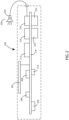
- FIG. 2 a schematic block diagram is shown with various components of a hearing assistance device in accordance with various embodiments.
- the block diagram of FIG. 2 represents a hearing assistance device for purposes of illustration.
- the ear-wearable device 100 shown in FIG. 2 includes several components electrically connected to a printed circuit board 218 (e.g., flexible printed circuit board) (e.g., flexible mother board) which is disposed within ear-wearable device housing 106.
- a power supply circuit 204 can include a battery and can be electrically connected to the printed circuit board 218 and provides power to the various components of the ear-wearable device 100.
- One or more microphones 206 are electrically connected to the printed circuit board 218, which provides electrical communication between the microphones 206 and a digital signal processor (DSP) 212.
- DSP digital signal processor
- the DSP 212 incorporates or is coupled to audio signal processing circuitry configured to implement various functions described herein.
- a sensor package 214 can be coupled to the DSP 212 via the printed circuit board 218.
- the sensor package 214 can include one or more different specific types of sensors such as those described in greater detail below.
- One or more user switches 210 are electrically coupled to the DSP 212 via the printed circuit board 218.
- An audio output device 216 is operatively connected to the DSP 212 via the printed circuit board 218.
- the audio output device 216 comprises a speaker (coupled to an amplifier).
- the audio output device 216 comprises an amplifier coupled to a receiver 226 adapted for positioning within an ear of a wearer.
- the receiver 226 can include a transducer (e.g., a speaker).
- An electrical filter component 230 may also be included, either within the ear-wearable device housing 106, in a receiver assembly 102, or in a different housing.
- An electrical filter 230 can help to reduce power consumption of the receiver 226.
- One example of a filter is an electrical inductor, which includes a coil in some embodiments. In some examples, the electrical inductor may have a value of between about 1-20 microhenry.
- the electrical filter component can be electrically connected to a signal output of the audio output device and to the positive input of the receiver. Alternatively, the electrical filter component can be electrically connected to a negative terminal of the audio output device and to the negative terminal of the receiver. In some embodiments, the electrical filter component is electrically connected to both a positive and negative terminal of the receiver and the audio output device.
- the ear-wearable device 100 may incorporate a communication device 208 coupled to the printed circuit board 218 and to an antenna 202 directly or indirectly via the printed circuit board 218.
- the communication device 208 can be a Bluetooth ® transceiver, such as conforms to a Bluetooth ® specification, for example, including but not limited to Bluetooth ® low energy (BLE), Bluetooth ® 4.2 or 5.0, and Bluetooth ® Long Range).
- Hearing assistance devices of the present disclosure can incorporate an antenna arrangement coupled to a high-frequency radio, such as a 2.4 GHz radio.
- the radio can conform to an IEEE 802.11 compliant device (e.g., WIFI ® ). It is understood that hearing assistance devices of the present disclosure can employ other radios, such as a 900 MHz radio.
- Hearing assistance devices of the present disclosure can be configured to receive streaming audio (e.g., digital audio data or files) from an electronic or digital source.
- Hearing assistance devices herein can also be configured to switch communication schemes to a long-range mode of operation, wherein, for example, one or more signal power outputs may be increased, and data packet transmissions may be slowed or repeated to allow communication to occur over longer distances than that during typical modes of operation.
- Representative electronic/digital sources include an assistive listening system, a TV streamer, a radio, a smartphone, a cell phone/entertainment device (CPED), a pendant, wrist-worn device, or other electronic device that serves as a source of digital audio data or files.
- CPED cell phone/entertainment device
- the communication device 208 can be configured to communicate with one or more external devices, such as those discussed previously, in accordance with various embodiments.
- the communication device 208 can be configured to communicate with an external visual display device such as a smart phone, a video display screen, a tablet, a computer, or the like.
- the ear-wearable device 100 can also include a control circuit 222 and a memory storage device 224.
- the control circuit 222 can be in electrical communication with other components of the device.
- the control circuit 222 can execute various operations, such as those described herein.
- the control circuit 222 can include various components including, but not limited to, a microprocessor, a microcontroller, an FPGA (field-programmable gate array) processing device, an ASIC (application specific integrated circuit), or the like.
- the memory storage device 224 can include both volatile and non-volatile memory.
- the memory storage device 224 can include ROM, RAM, flash memory, EEPROM, SSD devices, NAND chips, and the like.
- the memory storage device 224 can be used to store data from sensors as described herein and/or processed data generated using data from sensors as described herein, including, but not limited to, information regarding exercise regimens, performance of the same, visual feedback regarding exercises, and the like.
- the ear-wearable device can include a receiver assembly 102 connected to an earbud 104.
- the receiver assembly 102 can include a receiver housing 109 having a front housing portion 310 and a rear housing portion 312.
- the front housing portion 310 and rear housing portion 312 can each be formed from any suitable material or materials including, but not limited to silicone, urethane, acrylates, flexible epoxy, acrylate urethane, and combinations thereof.
- the front housing portion 310 and the rear housing portion 312 are formed from the same material.
- the front housing portion 310 and rear housing portion 312 may be formed from different materials from each other.
- the front housing portion 310 is manufactured to be removably attachable to the rear housing portion 312 by any combination of means including, but not limited to adhesives, snap fits, press fits, pin connections, or the like.
- the front housing portion 310 can be permanently attached to the rear housing portion 312 by any means including, but not limited to welding, ultrasonic welding, heat welding, soldering, adhesives, press-fit connections, snap-fit connections, heat staking, threading the components together, or the like.
- the front housing portion 310 can include a front housing wall 311 and can define a front housing volume 314.
- the rear housing portion 312 can include a rear housing wall 313 and can define a rear housing volume and/or a rear acoustic passage 316.
- the receiver assembly 102 may further include a receiver 318 configured to fit within the receiver housing 109.
- a receiver is any device that is configured to convert electrical signals into sounds.
- one or more microphones such as microphone 107 included in the in the ear-wearable device housing 106 of FIG. 1 ) gather acoustic energy (sound) from the surrounding environment and convert the acoustic energy into electrical signals.
- the electrical signals are then transmitted to an amplifier which performs various signal processing steps such as increasing the amplitude of the electric signals.
- the amplifier may perform further processing on the electrical signals such as filtering, compression, or the like.
- the amplified electric signals are then transmitted to the receiver 318, which converts the received electric signals into sounds (e.g., pressure waves configured to propagate through the acoustic environment).
- the sounds are then transmitted to a user's ear via an acoustic outlet 321 defined in the earbud 104.
- Any suitable type or types of receivers can be used in the ear-worn device including, but not limited to armature receivers, moving coil receivers, micro-electromechanical system (MEMS) speakers, or the like.
- MEMS micro-electromechanical system
- the receiver 318 is a moving coil receiver.
- a moving coil receiver also known as a dynamic receiver, as defined herein is a type of electroacoustic transducer used in various audio devices, including ear-wearable devices.
- Moving coil receivers typically contain a thin, lightweight coil of wire that is suspended within a magnetic field and attached to a diaphragm. The coil can be positioned within a permanent magnet, or an electromagnetic field created by a magnet. Electrical signals received from the ear-wearable device's amplifier are passed through the coil. These electrical signals create a varying electromagnetic field around the coil. As the electrical signals flow through the coil, the interaction between the electromagnetic field and the coil causes the coil and the attached diaphragm to vibrate.
- the vibration of the diaphragm produces sound waves that correspond to the electrical signals.
- the sound waves are emitted from the receiver. For instance, sounds can be emitted from the ear-wearable device 100 at acoustic outlet 321 and directed into the user's ear canal.
- a moving coil receiver includes a diaphragm with a diameter of at least 2, 4, 8, 9, 10, 11, 12, 13 or 14 millimeters (mm), or ranges between these values.
- the moving coil receiver has a diaphragm having a diameter of 13 mm.
- the receiver assembly 102 can include an insert 322 configured to fit within the receiver housing 109.
- the insert 322 can be placed within the receiver housing 109, such as to separate the front housing volume 314 from the rear acoustic passage 316.
- the insert 322 can have a first insert side 323 facing the front housing portion 310 and a second insert side 325 facing the rear housing wall 313.
- the receiver 318 is configured to fit within the receiver housing 109 between the front housing portion 310 and the first insert side 323.
- a portion of receiver 318 is supported by the insert 322.
- a portion of receiver 318 is supported by one or more ledges 327 defined within the rear housing wall 313.
- the receiver assembly 102 may further include one or more filters 230.
- Filter 230 can be configured to modify and enhance the incoming acoustic input by selectively amplifying or attenuating specific frequencies or sound characteristics.
- the filter 230 is configured to fit within the receiver housing 109 within a space defined by the insert 322.
- the receiver assembly 102 can include a receiver housing 109 having a front housing portion 310 and a rear housing portion 312.
- the receiver assembly can include one or more acoustic openings.
- the receiver assembly can include a rear acoustic inlet 422 defined in the rear housing wall 313 of the rear housing portion 312.
- the rear acoustic inlet 422 is in acoustic communication with the rear acoustic passage 316, which is in acoustic communication with the receiver 318.
- the rear housing wall 313 can further define one or more ambient openings 424.
- the receiver assembly 102 can include greater than or equal to one, two, three, or four ambient openings of any suitable size, shape, and configuration.
- the ambient openings 424 are in acoustic communication with the receiver 318.
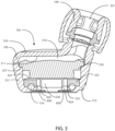
- FIG. 4 shows the bottom view without any mesh layers against the rear housing wall 313, so that the rear acoustic inlet 422 and ambient openings 424 are visible.
- the receiver assembly 102 can include a first mesh layer 528 and a second mesh layer 530.
- the first mesh layer 528 and the second mesh layer 530 can be formed from any suitable type of mesh (or other material having similar acoustic properties) such as acoustic mesh.
- Acoustic mesh as defined herein is a particular type of wire mesh used to achieve sound attenuation objectives.
- the first mesh layer 528 can have a first set of acoustic properties and the second mesh layer can have a second set of acoustic properties.
- the first mesh layer 528 and second mesh layer can have the same acoustic properties.
- the first mesh layer 528 and second mesh layer 530 and the second mesh layer can have different acoustic properties.
- the first mesh layer 528 can be formed from a denser weave than the second mesh layer 530 such that the first mesh layer is configured to provide greater sound attenuation and/or acoustic damping than the second mesh layer.
- the first mesh layer 528 can be formed from a less dense weave than the second mesh layer 530
- the first mesh layer 528 is configured to cover the ambient openings 424 on the rear housing wall 313.
- the first mesh layer 528 can be held by place by one or more features (e.g., protrusions and indentations) on the rear housing wall 313.
- the first mesh layer 528 includes a mesh aperture 529 configured to interface with a protrusion 531 defined by the rear housing wall 313 and the first mesh layer 528 can sit within a first indentation 532 of the rear housing wall 313.
- the first mesh layer does not cover the rear acoustic inlet 422.
- the first mesh layer can cover the rear acoustic inlet 422.
- the second mesh layer 530 is configured to cover the ambient openings 424 and the rear acoustic inlet 422 on the rear housing wall 313.
- the second mesh layer 530 is stacked on top of the first mesh layer 528, but in alterative embodiments, the first mesh layer 528 may be stacked on top of the second mesh layer 530.
- the second mesh layer 530 can be held by place by one or more features (e.g., protrusions and indentations) defined on the rear housing wall 313. For instance, the second mesh layer 530 can sit within a second indentation 534 of the rear housing wall 313.
- the first mesh layer 528 and the second mesh layer 530 are distributed over the various openings of the rear housing wall 313 to optimize their acoustic damping effects.
- the mesh densities can be selected to provide the best acoustic properties for a particular ear-worn device configuration.
- the mesh layers 528, 530 can also provide ingress protection to the rear acoustic volume.
- FIG. 3 shows a receiver assembly having two mesh layers.
- the receiver assembly 102 may have any suitable number of mesh layers such as one, two, three, four, or more mesh layer distributed in any suitable configuration over the rear acoustic inlet 422 and the ambient openings 424.
- FIG. 6 Receiver Assembly Exploded View
- the receiver assembly 102 can include an earbud 104, a first mesh layer 528, a second mesh layer 530, and a receiver housing formed from a front housing portion 310 and a rear housing portion 312.
- the receiver housing can include at least a receiver 318, a filter component 230, and an insert 322.
- the earbud 104 can be removably attachable to the front housing portion 310 of the receiver assembly 102.
- the earbud 104 can include one or more layers of mesh.
- the receiver assembly can include a first earbud mesh layer 632 and a second earbud mesh layer 633.
- the first earbud mesh layer 632 and the second earbud mesh layer 633 are configured to prevent foreign matter from entering the receiver housing 109 through the earbud 104 and can be designed with any suitable acoustic properties to optimize sound quality.
- the first earbud mesh layer 632 and the second earbud mesh layer 633 can be separated from each other within the receiver assembly 102 by a fixed axial distance.
- the first earbud mesh layer 632 can be disposed within the earbud 104 and the second earbud mesh layer 633 can be disposed on the top of the stem 842 (best seen in FIG. 8 ) of the receiver housing 109.
- the receiver assembly 102 may include only one of mesh layers 632, 633 or may not include any mesh layers in the earbud 104 or stem 842.
- the receiver assembly 102 can include an insert 322 configured to fit within the receiver housing 109.
- the insert 322 can be placed within the receiver housing 109, such as to separate the front housing volume 314 from the rear acoustic passage 316.
- the insert 322 can partially define the rear acoustic passage 316.
- the insert 322 can have one or more openings spanning from the first insert side 323 to the second insert side 325.
- the insert can have a first insert opening 638 configured to form a portion of the rear acoustic passage 316.
- the insert can further include a second insert opening 639 configured to hold the filter 230 within the receiver housing 109.
- the second insert opening 639 is configured to be slightly larger than the filter 230, in at least one dimension.
- the second insert opening 639 can have a protruding portion on either side.
- the second insert opening 639 is in acoustic communication with the ambient openings 424 defined in the rear housing wall 313.
- the second inset opening leaves a gap in the receiver housing such that the ambient openings 424 are in fluid communication with the receiver 318.
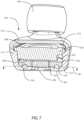
- FIG. 7 is a cross sectional view of a receiver assembly through the rear acoustic inlet 422, shown in accordance with various embodiments herein.
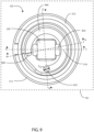
- FIG. 8 is a cross sectional view of a receiver assembly through a receiver inlet 840, shown in accordance with various embodiments herein.
- the receiver assembly 102 can include a rear acoustic passage 316 defined between the rear housing wall 313 and the second insert side 325.
- the receiver assembly can define venting passages leading to the rear side of the receiver.
- the receiver assembly can also device a front acoustic passage leading to an earbud.
- the rear acoustic passage 316 begins at the rear acoustic inlet 422 (best seen in FIG. 7 ).
- the rear acoustic passage 316 extends through the space defined between the rear housing wall 313 and the second insert side 325.
- the rear acoustic passage 316 extends up though the first insert opening 638 and terminates at the receiver inlet 840 (best seen in FIG. 8 ).
- the receiver housing 109 is configured to permit fluid communication between an external environment and the receiver rear side 636 through the rear acoustic inlet 422 and the rear acoustic passage 316. This fluid communication facilitates the easier movement of the receiver, compared to if the housing was closed to fluid communication.
- the air in the rear acoustic passage 316 provides a suspension effect to the receiver, allowing smoother movement and facilitating high-quality sound production particularly at lower frequencies.
- the rear acoustic passage 316 can have an annular cross section and can be partial defined by the rear housing wall 313 and partially defined by the second insert side 325.
- approximately half of the cross-sectional area of the rear acoustic passage 316 is defined by the rear housing wall 313, approximately half of the cross-sectional area of the rear acoustic passage 316 is defined by the second insert side 325, and the two halves are combined to form a rear acoustic passage having a substantially circular cross section.
- most conventional manufacturing processes e.g., injection molding, 3D printing
- such a configuration is simpler than forming an acoustic passage in a singular piece of material.
- the rear acoustic passage 316 may be defined entirely by the rear housing wall 313 or the rear acoustic passage 316 may be defined entirely by second insert side 325. While the rear acoustic passage 316 is depicted as having a substantially circular cross-sectional area in FIGS. 7-8 , it is possible for the rear acoustic passage to have any other suitable cross-sectional shape such as oval, square, or the like.
- the rear housing and insert may be formed using injection molding, 3D printing, compression molding, or other manufacturing processes.
- the acoustic output from the receiver 318 is propagated through the front housing volume 314.
- the front housing volume 314 is formed between a receiver front side 634 and the front housing wall 311.
- the front housing portion 310 includes a stem 842 protruding from the front housing wall 311.
- the stem 842 can define a front acoustic passage 844.
- the front acoustic passage 844 is in fluid communication with the front housing volume 314.
- the acoustic output passes through the front housing volume 314 and front acoustic passage 844 into the ear canal of the ear-wearable device user through the acoustic outlet 321 defined in the earbud 104.
- the rear housing wall 313 can further define one or more ambient openings 424.
- the ambient openings 424 are in acoustic communication with the receiver rear side 636 via rear vent passages 850.
- the ambient openings 424 are configured to provide venting to the receiver rear side 636 of the receiver 318. Venting can improve the sound quality of the amplified sounds, by allowing the receiver rear side 636 to move as it generates sound.
- the benefits of the venting provided by the ambient openings 424 and the rear vent passages 850 can be optimized using one or more mesh layers with acoustic properties, as discussed in the context of FIG. 5 .
- FIG. 9 is a cross sectional view of a receiver assembly through the rear acoustic passage plane shown in accordance with various embodiments herein, looking towards the rear housing wall of the receiver housing.
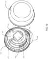
- FIG. 10 is a partially exploded view of a receiver assembly, where the rear housing portion 312 is removed from the receiver assembly to reveal the second insert side 325, in accordance with various embodiments herein.
- the rear acoustic passage 316 can include a curved portion 944 between the rear acoustic inlet 422 and the receiver inlet 840.
- the curved portion 944 can be defined in both the rear housing wall 313 (best seen in FIG. 9 ) and in the second insert side 325 (best seen in FIG. 10 ).
- the curved portion may be defined only by the rear housing wall 313 or only by an insert component.
- the curved portion 944 of the rear acoustic passage 316 has an arc shape in a plane parallel to at least a portion of the rear housing wall.
- acoustic passage includes curved surfaces and does not include hard corners or right angles, to reduce the chance of echoes.
- FIG. 9 includes dashed line 3-3 showing the cross-sectional plane of FIG. 3 through the ambient openings 424.
- FIG. 9 also includes dashed line 7-7 showing the cross-sectional plane of FIG. 7 through the rear acoustic inlet 422.
- FIG. 9 also includes dashed line 8-8 showing the cross-sectional plane of FIG. 8 through the receiver inlet 840.
- the rear acoustic passage 316 can include a first axial portion 739 extending away from the rear acoustic inlet 422 to the rear acoustic passage plane 741.
- the rear acoustic passage 316 can include a second axial portion 841 extending from the rear acoustic passage plane 741 through the first insert opening 638 to the receiver inlet 840.
- the curved portion 944 of the rear acoustic passage 316 can be defined between the first axial portion 739 and the second axial portion 841 and is configured to intersect the rear acoustic passage plane 741.
- the shape of an acoustic passage can significantly affect the receiver's acoustic resonance properties and its efficiency in transmitting various acoustic frequencies.
- the curved shape of the rear acoustic passage 316 allows for more flexibility in acoustic passage tuning.
- the rear acoustic passage 316 is tuned to increase a low frequency efficiency of the receiver 318.
- a longer and narrower cylinder will be "heavy” and provide more resistance to the travel of sound when compared to a short and wide cylinder with a "light” effect on the receiver.
- the acoustic mass together with the rear volume and the receiver's mechanical stiffness determine a resonant frequency.
- a design for an ear-wearable device can have a desired resonant frequency and these parameters can be adjusted to achieve the desired resonant frequency.
- the acoustic mass can be greater than or equal to 4000, 7200, 10400, 13600, 16800, or 20000 kg/m 4 . In some embodiments, the acoustic mass can be less than or equal to 100000, 84000, 68000, 52000, 36000, or 20000 kg/m 4 . In some embodiments, the acoustic mass can fall within a range of 4000 to 100000 kg/m 4 , or 7200 to 84000 kg/m 4 , or 10400 to 68000 kg/m 4 , or 13600 to 52000 kg/m 4 , or 16800 to 36000 kg/m 4 , or can be about 20000 kg/m 4 .
- the length of the rear acoustic passage 316 as defined herein is the distance between the rear acoustic inlet 422 and the receiver inlet 840 and can include the first axial portion 739, second axial portion 841, and the curved portion 944.
- the length of the rear acoustic passage can be greater than or equal to 9 mm, 11 mm, 12 mm, 14 mm, 16 mm, 17 mm, or 19 mm.
- the length of the rear acoustic passage can be less than or equal to 29 mm, 27 mm, 26 mm, 24 mm, 22 mm, 21 mm, or 19 mm.
- the length of the rear acoustic passage can fall within a range of 9 mm to 29 mm, or 11 mm to 27 mm, or 12 mm to 26 mm, or 14 mm to 24 mm, or 16 mm to 22 mm, or 17 mm to 21 mm, or can be about 19 mm.
- the cross-sectional area of the rear acoustic passage 316 is determined by its diameter, which is labeled D AP in FIG. 9 .
- the diameter can be greater than or equal to 0.3 mm, 0.4 mm, 0.6 mm, 0.8 mm, 0.9 mm, 1.0 mm, or 1.2 mm.
- the diameter can be less than or equal to 5.0 mm, 4.4 mm, 3.7 mm, 3.1 mm, 2.5 mm, 1.8 mm, or 1.2 mm.
- the diameter can fall within a range of 0.3 mm to 5.0 mm, or 0.4 mm to 4.4 mm, or 0.6 mm to 3.7 mm, or 0.8 mm to 3.1 mm, or 0.9 mm to 2.5 mm, or 1.0 mm to 1.8 mm, or can be about 1.2 mm.
- the ratio of length to diameter can play a key role in the resonance properties of the rear acoustic passage 316.
- the ratio of length to diameter can be greater than or equal to 6, 8, 10, 12, 14, or 16.
- the ratio of length to diameter can be less than or equal to 26, 24, 22, 20, 18, or 16.
- the ratio of length to diameter can fall within a range of 6 to 26, or 8 to 24, or 10 to 22, or 12 to 20, or 14 to 18, or can be about 16.
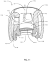
- the earbud 104 can have a first earbud portion 1141 and a second earbud portion 1143.
- the earbud 104 is configured to be removably attachable to the stem 842 of the receiver housing 109 at the first earbud portion 1141.
- the removable attachability of the earbud 104 from the receiver housing 109 facilitates easy cleaning and replacement of the earbud 104.
- the first earbud portion 1141 can include one or more retention features 1148 such that the earbud stays securely attached to the stem of the receiver housing 109.
- the first earbud portion 1141 can include a flange configured to snap onto a corresponding groove on the stem 842 of the receiver housing 109.
- the retention features 1148 are further configured to hold the first earbud mesh layer 632 in place within the earbud 104.
- the first earbud portion 1141 can be constructed from any suitable material or materials with sufficient ductility to snap onto the receiver housing, but sufficient rigidity to maintain its shape including, but not limited to silicone, urethane, acrylates, flexible epoxy, acrylate urethane, and combinations thereof.
- the earbud 104 can include a second earbud portion 1143.
- the second earbud portion 1143 can be permanently attached to the first earbud portion 1141 by any suitable means such as welding, adhesives, or the like.
- the second earbud portion 1143 can be constructed from a less rigid material than the first earbud portion 1141.
- the second earbud portion 1143 is made from a material and constructed so that it uniformly conforms to the ear canal and maintains a constant and comfortable radial pressure on the ear canal.
- the second earbud portion 1143 is made of resilient material, such as silicone.
- the second earbud portion 1143 is made of a flexible material.
- the second earbud portion 1143 is made of an elastomeric material.
- elastomeric material it is meant a material with viscoelasticity that is soft and deformable at ambient temperatures, such as rubber, silicone, and amorphous polymers.
- the second earbud portion 1143 can be constructed from the same material as the first earbud portion 1141.
- the earbud 104 can include an axial wall 1150 defining an earbud acoustic channel 1152.
- the earbud acoustic channel 1152 can be in acoustic communication with the front acoustic passage 844.
- the earbud acoustic channel 1152 terminates at acoustic outlet 321.
- the axial wall 1150 is formed partially from the first earbud portion 1141 and partially from the second earbud portion 1143.
- the second earbud portion 1143 can form an outer dome 1138.
- the outer dome can be connected to the axial wall 1150 at flexible tip portion 1146 of the earbud.
- the outer dome can be unconnected to the axial wall at a rear edge 1154 of the earbud to further enhance the complaint fit of the earbud.
- the earbud can include a plurality of vent openings 1142 defined in the axial wall 1150.
- the earbud can include any suitable number, shape, and configuration of vent openings 1142 defined in the axial wall 1150 such as one, two, three, four, or more vent openings.
- the plurality of vent openings 1142 are configured to give the earbud 104 an open fit. Unlike traditional in-ear earphones, which create a seal inside the ear canal to isolate the ear canal from external sounds, open-fit earbuds allow some ambient noise to pass through. Open fit devices can be prone to "tinny" audio (e.g., attenuation of low frequency sound).
- ambient sounds can follow an acoustic path such as exemplary path 1156.
- ambient sounds can enter the earbud 104 through the open end of the outer dome 1138 at the rear edge 1154, pass through the earbud acoustic channel 1152 through one of the vent openings 1142, and then enter the wearer's ear though the acoustic outlet 321.
- the earbud 104 can be devoid of vent openings 1142 and provide a closed fit.
- the earbud 104 is devoid of vent openings 1142 on the outer dome 1138. Accordingly, when viewing the earbud 104 from the outside, it will appear to have a closed fit. Such a configuration is advantageous because vent openings 1142 on an outer surface of the earbud 104 would be occluded by the user's ear canal and could provide an inlet for foreign matter to the earbud 104.
- the phrase “configured” describes a system, apparatus, or other structure that is constructed or configured to perform a particular task or adopt a particular configuration.
- the phrase “configured” can be used interchangeably with other similar phrases such as arranged and configured, constructed and arranged, constructed, manufactured and arranged, and the like.
- the invention relates, inter alia, to the following aspects:
Landscapes
- Engineering & Computer Science (AREA)
- Physics & Mathematics (AREA)
- Acoustics & Sound (AREA)
- Signal Processing (AREA)
- Health & Medical Sciences (AREA)
- Otolaryngology (AREA)
- Manufacturing & Machinery (AREA)
- Headphones And Earphones (AREA)
Applications Claiming Priority (1)
| Application Number | Priority Date | Filing Date | Title |
|---|---|---|---|
| US202363604654P | 2023-11-30 | 2023-11-30 |
Publications (1)
| Publication Number | Publication Date |
|---|---|
| EP4564846A1 true EP4564846A1 (fr) | 2025-06-04 |
Family
ID=91082201
Family Applications (1)
| Application Number | Title | Priority Date | Filing Date |
|---|---|---|---|
| EP24175764.0A Withdrawn EP4564846A1 (fr) | 2023-11-30 | 2024-05-14 | Ensemble récepteur avec passage acoustique arrière pour un dispositif pouvant être porté sur l'oreille |
Country Status (1)
| Country | Link |
|---|---|
| EP (1) | EP4564846A1 (fr) |
Citations (8)
| Publication number | Priority date | Publication date | Assignee | Title |
|---|---|---|---|---|
| EP1874080A2 (fr) * | 2006-06-30 | 2008-01-02 | Bose Corporation | Ecouteurs |
| US20080298623A1 (en) * | 2005-07-19 | 2008-12-04 | Nxp B.V. | Adapter For a Loudspeaker |
| WO2014039384A1 (fr) * | 2012-09-07 | 2014-03-13 | Bose Corporation | Combinaison et imperméabilisation vis-à-vis de l'eau de sorties d'orifice d'écouteur |
| US9848273B1 (en) | 2016-10-21 | 2017-12-19 | Starkey Laboratories, Inc. | Head related transfer function individualization for hearing device |
| US20180317837A1 (en) | 2017-05-08 | 2018-11-08 | Starkey Laboratories, Inc. | Hearing assistance device incorporating virtual audio interface for therapy guidance |
| US20180343527A1 (en) | 2006-07-10 | 2018-11-29 | Starkey Laboratories, Inc. | Method and apparatus for a binaural hearing assistance system using monaural audio signals |
| WO2020055167A1 (fr) * | 2018-09-12 | 2020-03-19 | 이근형 | Écouteur comprenant une structure destinée à améliorer la qualité du son |
| WO2020069374A1 (fr) * | 2018-09-28 | 2020-04-02 | Apple Inc. | Embouts pour couplage par l'intermédiaire de mécanismes de fixation de forme de fil |
-
2024
- 2024-05-14 EP EP24175764.0A patent/EP4564846A1/fr not_active Withdrawn
Patent Citations (8)
| Publication number | Priority date | Publication date | Assignee | Title |
|---|---|---|---|---|
| US20080298623A1 (en) * | 2005-07-19 | 2008-12-04 | Nxp B.V. | Adapter For a Loudspeaker |
| EP1874080A2 (fr) * | 2006-06-30 | 2008-01-02 | Bose Corporation | Ecouteurs |
| US20180343527A1 (en) | 2006-07-10 | 2018-11-29 | Starkey Laboratories, Inc. | Method and apparatus for a binaural hearing assistance system using monaural audio signals |
| WO2014039384A1 (fr) * | 2012-09-07 | 2014-03-13 | Bose Corporation | Combinaison et imperméabilisation vis-à-vis de l'eau de sorties d'orifice d'écouteur |
| US9848273B1 (en) | 2016-10-21 | 2017-12-19 | Starkey Laboratories, Inc. | Head related transfer function individualization for hearing device |
| US20180317837A1 (en) | 2017-05-08 | 2018-11-08 | Starkey Laboratories, Inc. | Hearing assistance device incorporating virtual audio interface for therapy guidance |
| WO2020055167A1 (fr) * | 2018-09-12 | 2020-03-19 | 이근형 | Écouteur comprenant une structure destinée à améliorer la qualité du son |
| WO2020069374A1 (fr) * | 2018-09-28 | 2020-04-02 | Apple Inc. | Embouts pour couplage par l'intermédiaire de mécanismes de fixation de forme de fil |
Similar Documents
| Publication | Publication Date | Title |
|---|---|---|
| US11540036B2 (en) | Flanged earbud and hearing device including same | |
| US11234085B2 (en) | Earpieces and related articles and devices | |
| US10939217B2 (en) | Audio device with acoustic valve | |
| CN209402687U (zh) | 听力装置 | |
| CN101106831B (zh) | 放在耳内的耳机 | |
| CN101455092B (zh) | 个人收听设备 | |
| EP4197198B1 (fr) | Réalisation d'orifices d'oreillette | |
| US10142735B2 (en) | Dual mode headphone and method therefor | |
| CN112788459B (zh) | 与管道结合成一体的接收器模块 | |
| US10972822B2 (en) | Headphones with an ergonomic cushion and an ergonomic cushion thereof | |
| CN102318368A (zh) | 耳机 | |
| US20200213776A1 (en) | External ear insert for hearing enhancement | |
| US9668067B2 (en) | Hearing device with improved low frequency response and method for manufacturing such a hearing device | |
| WO2023097740A1 (fr) | Haut-parleur composite et appareil de production sonore | |
| CN116615916A (zh) | 具有动圈式换能器和声学后腔体积的听筒 | |
| US11178497B2 (en) | In-ear receiver | |
| EP4564846A1 (fr) | Ensemble récepteur avec passage acoustique arrière pour un dispositif pouvant être porté sur l'oreille | |
| EP4615006A1 (fr) | Suspension d'isolation contre les vibrations pour composants audio pouvant être portés sur l'oreille | |
| US12143767B1 (en) | Earphone bidirectional pressure port | |
| EP4231662A1 (fr) | Dispositif d'aide auditive avec contrôle actif du bruit | |
| JP6931753B1 (ja) | 電気音響アクチュエータ | |
| CN120018041A (zh) | 具有软通风口的助听器 | |
| CN116896702A (zh) | 听力装置 | |
| EP3318071A1 (fr) | Insert auriculaire externe pour améliorer l'audition |
Legal Events
| Date | Code | Title | Description |
|---|---|---|---|
| PUAI | Public reference made under article 153(3) epc to a published international application that has entered the european phase |
Free format text: ORIGINAL CODE: 0009012 |
|
| STAA | Information on the status of an ep patent application or granted ep patent |
Free format text: STATUS: THE APPLICATION HAS BEEN PUBLISHED |
|
| AK | Designated contracting states |
Kind code of ref document: A1 Designated state(s): AL AT BE BG CH CY CZ DE DK EE ES FI FR GB GR HR HU IE IS IT LI LT LU LV MC ME MK MT NL NO PL PT RO RS SE SI SK SM TR |
|
| STAA | Information on the status of an ep patent application or granted ep patent |
Free format text: STATUS: THE APPLICATION IS DEEMED TO BE WITHDRAWN |
|
| 18D | Application deemed to be withdrawn |
Effective date: 20251205 |