EP4565040A2 - Lichtemittierende vorrichtung - Google Patents
Lichtemittierende vorrichtung Download PDFInfo
- Publication number
- EP4565040A2 EP4565040A2 EP24216147.9A EP24216147A EP4565040A2 EP 4565040 A2 EP4565040 A2 EP 4565040A2 EP 24216147 A EP24216147 A EP 24216147A EP 4565040 A2 EP4565040 A2 EP 4565040A2
- Authority
- EP
- European Patent Office
- Prior art keywords
- light emitting
- light
- coordinate
- color temperature
- emitting elements
- Prior art date
- Legal status (The legal status is an assumption and is not a legal conclusion. Google has not performed a legal analysis and makes no representation as to the accuracy of the status listed.)
- Pending
Links
Images





Classifications
-
- H—ELECTRICITY
- H10—SEMICONDUCTOR DEVICES; ELECTRIC SOLID-STATE DEVICES NOT OTHERWISE PROVIDED FOR
- H10H—INORGANIC LIGHT-EMITTING SEMICONDUCTOR DEVICES HAVING POTENTIAL BARRIERS
- H10H29/00—Integrated devices, or assemblies of multiple devices, comprising at least one light-emitting semiconductor element covered by group H10H20/00
- H10H29/10—Integrated devices comprising at least one light-emitting semiconductor component covered by group H10H20/00
- H10H29/14—Integrated devices comprising at least one light-emitting semiconductor component covered by group H10H20/00 comprising multiple light-emitting semiconductor components
-
- H—ELECTRICITY
- H05—ELECTRIC TECHNIQUES NOT OTHERWISE PROVIDED FOR
- H05B—ELECTRIC HEATING; ELECTRIC LIGHT SOURCES NOT OTHERWISE PROVIDED FOR; CIRCUIT ARRANGEMENTS FOR ELECTRIC LIGHT SOURCES, IN GENERAL
- H05B47/00—Circuit arrangements for operating light sources in general, i.e. where the type of light source is not relevant
- H05B47/10—Controlling the light source
- H05B47/105—Controlling the light source in response to determined parameters
-
- F—MECHANICAL ENGINEERING; LIGHTING; HEATING; WEAPONS; BLASTING
- F21—LIGHTING
- F21V—FUNCTIONAL FEATURES OR DETAILS OF LIGHTING DEVICES OR SYSTEMS THEREOF; STRUCTURAL COMBINATIONS OF LIGHTING DEVICES WITH OTHER ARTICLES, NOT OTHERWISE PROVIDED FOR
- F21V29/00—Protecting lighting devices from thermal damage; Cooling or heating arrangements specially adapted for lighting devices or systems
- F21V29/50—Cooling arrangements
- F21V29/70—Cooling arrangements characterised by passive heat-dissipating elements, e.g. heat-sinks
-
- F—MECHANICAL ENGINEERING; LIGHTING; HEATING; WEAPONS; BLASTING
- F21—LIGHTING
- F21V—FUNCTIONAL FEATURES OR DETAILS OF LIGHTING DEVICES OR SYSTEMS THEREOF; STRUCTURAL COMBINATIONS OF LIGHTING DEVICES WITH OTHER ARTICLES, NOT OTHERWISE PROVIDED FOR
- F21V29/00—Protecting lighting devices from thermal damage; Cooling or heating arrangements specially adapted for lighting devices or systems
- F21V29/85—Protecting lighting devices from thermal damage; Cooling or heating arrangements specially adapted for lighting devices or systems characterised by the material
- F21V29/89—Metals
-
- H—ELECTRICITY
- H05—ELECTRIC TECHNIQUES NOT OTHERWISE PROVIDED FOR
- H05B—ELECTRIC HEATING; ELECTRIC LIGHT SOURCES NOT OTHERWISE PROVIDED FOR; CIRCUIT ARRANGEMENTS FOR ELECTRIC LIGHT SOURCES, IN GENERAL
- H05B45/00—Circuit arrangements for operating light-emitting diodes [LED]
- H05B45/10—Controlling the intensity of the light
-
- H—ELECTRICITY
- H05—ELECTRIC TECHNIQUES NOT OTHERWISE PROVIDED FOR
- H05B—ELECTRIC HEATING; ELECTRIC LIGHT SOURCES NOT OTHERWISE PROVIDED FOR; CIRCUIT ARRANGEMENTS FOR ELECTRIC LIGHT SOURCES, IN GENERAL
- H05B45/00—Circuit arrangements for operating light-emitting diodes [LED]
- H05B45/20—Controlling the colour of the light
-
- H—ELECTRICITY
- H05—ELECTRIC TECHNIQUES NOT OTHERWISE PROVIDED FOR
- H05B—ELECTRIC HEATING; ELECTRIC LIGHT SOURCES NOT OTHERWISE PROVIDED FOR; CIRCUIT ARRANGEMENTS FOR ELECTRIC LIGHT SOURCES, IN GENERAL
- H05B47/00—Circuit arrangements for operating light sources in general, i.e. where the type of light source is not relevant
- H05B47/10—Controlling the light source
- H05B47/155—Coordinated control of two or more light sources
-
- H—ELECTRICITY
- H05—ELECTRIC TECHNIQUES NOT OTHERWISE PROVIDED FOR
- H05B—ELECTRIC HEATING; ELECTRIC LIGHT SOURCES NOT OTHERWISE PROVIDED FOR; CIRCUIT ARRANGEMENTS FOR ELECTRIC LIGHT SOURCES, IN GENERAL
- H05B47/00—Circuit arrangements for operating light sources in general, i.e. where the type of light source is not relevant
- H05B47/10—Controlling the light source
- H05B47/16—Controlling the light source by timing means
-
- H—ELECTRICITY
- H10—SEMICONDUCTOR DEVICES; ELECTRIC SOLID-STATE DEVICES NOT OTHERWISE PROVIDED FOR
- H10H—INORGANIC LIGHT-EMITTING SEMICONDUCTOR DEVICES HAVING POTENTIAL BARRIERS
- H10H29/00—Integrated devices, or assemblies of multiple devices, comprising at least one light-emitting semiconductor element covered by group H10H20/00
- H10H29/80—Constructional details
- H10H29/85—Packages
- H10H29/851—Wavelength conversion means
- H10H29/8511—Wavelength conversion means characterised by their material, e.g. binder
- H10H29/8512—Wavelength conversion materials
- H10H29/8513—Wavelength conversion materials having two or more wavelength conversion materials
-
- F—MECHANICAL ENGINEERING; LIGHTING; HEATING; WEAPONS; BLASTING
- F21—LIGHTING
- F21V—FUNCTIONAL FEATURES OR DETAILS OF LIGHTING DEVICES OR SYSTEMS THEREOF; STRUCTURAL COMBINATIONS OF LIGHTING DEVICES WITH OTHER ARTICLES, NOT OTHERWISE PROVIDED FOR
- F21V3/00—Globes; Bowls; Cover glasses
- F21V3/04—Globes; Bowls; Cover glasses characterised by materials, surface treatments or coatings
Definitions
- the present disclosure relates to a light emitting device.
- lighting devices installed indoors are manufactured in various forms and shapes, and their configuration includes a main body, to be fixed to a ceiling or wall, etc., which has a light source that emits light and various parts related thereto, and a light-transmitting cover which is manufactured to maintain illumination and to form an attractive appearance.
- the embodiments of the present disclosure provide a light emitting device that generates light similar to natural light.
- the embodiments of the present disclosure provide a light emitting device with vivid color reproduction.
- the embodiments of the present disclosure achieve a high quality light emitting device with low chromatic aberration.
- a light emitting device including: a plurality of light emitting elements that emit light within a predetermined color temperature region on a color coordinate system, wherein an average of color coordinate values of
- the light emitting device in which the color temperature region has four vertices defined by a first coordinate, a second coordinate, a third coordinate, and a fourth coordinate on the color coordinate system, wherein the first coordinate has an x-value smaller than x-values of the second coordinate and the third coordinate, and a y-value smaller than y-values of the second coordinate, the third coordinate, and the fourth coordinate, wherein the second coordinate has a y-value smaller than the y-values of the third coordinate and the fourth coordinate, wherein the third coordinate has a y-value greater than the y-values of the first coordinate, the second coordinate, and the fourth coordinate, and an x-value greater than the first coordinate and the fourth coordinate, and wherein the fourth coordinate has a y-value greater than the y-values of the first coordinate and the second coordinate and smaller than the y-value of the third coordinate, and an x-value smaller than the x-values of the second coordinate and the third coordinate.
- the light emitting device in which the color temperature region has an elliptical shape on the color coordinate system.
- the light emitting device in which the color temperature region is inclined at a predetermined angle with respect to an x-axis on the color coordinate system.
- the light emitting device in which the predetermined angle ranges from 40° to 70°.
- the light emitting device in which a length of a major axis of the color temperature region ranges from 0.0110 to 0.0144.
- the light emitting device in which a length of the minor axis of the color temperature region ranges from 0.0045 to 0.0066.
- the light emitting device in which the color temperature of the light emitted by the plurality of light emitting elements ranges from 1700K to 7000K.
- the light emitting device in which the first color temperature region has the largest central color coordinate x- and y-values among the plurality of color temperature regions, and the second color temperature region has the smallest central color coordinate x- and y-values among the plurality of color temperature regions, and the controller controls the intensity of light emitted from the plurality of first light emitting elements and the intensity of light emitted from the second light emitting elements such that the average of the color coordinate values of the plurality of light emitting elements moves from one of the first color temperature region and the second color temperature region toward the other of the first color temperature region and the second color temperature region.
- the controller increases the intensity of light emitted from the plurality of first light emitting elements and decreases the intensity of light emitted from the plurality of second light emitting elements so that the average of the color coordinate values of the plurality of light emitting elements to move towards the first color temperature region.
- the controller decreases the intensity of light emitted from the plurality of first light emitting elements and increases the intensity of light emitted from the plurality of second light emitting elements so that the average of the color coordinate values of the plurality of light emitting elements to move towards the second color temperature region.
- the light emitting device in which the controller controls the intensity of light emitted from the plurality of first light emitting elements and the intensity of light emitted from the plurality of second light emitting elements to be equal so that the average of the color coordinate values of the plurality of light emitting elements is disposed in a center of the first color temperature region and the second color temperature region while being disposed within one of the plurality of color temperature regions.
- the light emitting device in which the plurality of color temperature regions have rectangular shapes on the color coordinate system and at least some of which are in contact with each other.
- the light emitting device in which a size of the first color temperature region is larger than a size of the second color temperature region.
- the light emitting device in which the plurality of color temperature regions have elliptical shapes on the color coordinate system and are arranged to be spaced apart from each other.
- the light emitting device in which the plurality of color temperature regions are arranged at a predetermined angle with respect to an x-axis of the color coordinate system.
- the light emitting device in which an angle at which the first color temperature region is inclined is different from an angle at which the second color temperature region is inclined.
- the light emitting device in which the light emitter includes: a first light emitting element for generating light within a first color temperature region among a plurality of color temperature regions on a color coordinate system; and a second light emitting element for generating light within a second color temperature region that is different from the first color temperature region among the plurality of color temperature regions, and the controller stores light intensity data for adjusting an intensity of light from the first light emitting element and an intensity of light from the second light emitting element.
- the light emitting device can generate light similar to natural light. Further, it is possible to provide the light emitting with vivid color reproduction. In addition, it is possible to achieve a high quality light emitting device with low chromatic aberration.
- the illustrated exemplary embodiments are to be understood as providing exemplary features of varying detail of some ways in which the inventive concepts may be implemented in practice. Therefore, unless otherwise specified, the features, components, modules, layers, films, panels, regions, and/or aspects (hereinafter individually or collectively referred to as "elements") of the various embodiments may be otherwise combined, separated, interchanged, and/or rearranged without departing from the inventive concepts.
- an element such as a layer
- it may be directly on, connected to, or coupled to the other element or layer or intervening elements or layers may be present.
- an element or layer is referred to as being “directly on,” “directly connected to,” or “directly coupled to” another element or layer, there are no intervening elements or layers present.
- the term “connected” may refer to physical, electrical, and/or fluid connection, with or without intervening elements.
- the DR1-axis, the DR2-axis, and the DR3-axis are not limited to three axes of a rectangular coordinate system, such as the x, y, and z-axes, and may be interpreted in a broader sense.
- the DR1-axis, the DR2-axis, and the DR3-axis may be perpendicular to one another, or may represent different directions that are not perpendicular to one another.
- X, Y, and Z and "at least one selected from the group consisting of X, Y, and Z” may be construed as X only, Y only, Z only, or any combination of two or more of X, Y, and Z, such as, for instance, XYZ, XYY, YZ, and ZZ.
- the term “and/or” includes any and all combinations of one or more of the associated listed items.
- exemplary embodiments are described herein with reference to sectional and/or exploded illustrations that are schematic illustrations of idealized exemplary embodiments and/or intermediate structures. As such, variations from the shapes of the illustrations as a result, for example, of manufacturing techniques and/or tolerances, are to be expected. Thus, exemplary embodiments disclosed herein should not necessarily be construed as limited to the particular illustrated shapes of regions, but are to include deviations in shapes that result from, for instance, manufacturing. In this manner, regions illustrated in the drawings may be schematic in nature and the shapes of these regions may not reflect actual shapes of regions of a device and, as such, are not necessarily intended to be limiting.
- each block, unit, and/or module may be implemented by dedicated hardware, or as a combination of dedicated hardware to perform some functions and a processor (for example, one or more programmed microprocessors and associated circuitry) to perform other functions.
- each block, unit, and/or module of some exemplary embodiments may be physically separated into two or more interacting and discrete blocks, units, and/or modules without departing from the scope of the inventive concepts.
- the blocks, units, and/or modules of some exemplary embodiments may be physically combined into more complex blocks, units, and/or modules without departing from the scope of the inventive concepts.
- the light emitting device is a device that can generate light.
- the light emitting device can be installed indoors, but is not limited to that. It can be controlled by a switch provided on the wall of an indoor space to generate light or can be controlled by a terminal to emit light.
- a correlated color temperature of the light generated by the light emitting device can be formed to be similar to that of natural light.
- Natural light is a light emitted from the sun toward a space where the light emitting device is installed, and it can vary depending on time and weather.
- the light emitting device can generate light with the correlated color temperature that changes with time and weather, but is not limited thereto.
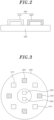
- the light emitting device 1 may include a housing 100, a heat sink 200, a cover 300, a light emitter 400, a power distributor 500, and a controller 600, and may further include a microphone 700.
- the housing 100 can accommodate the heat sink 200, light emitter 400, and controller 600.
- the housing 100 may have an opening formed on one side to accommodate the heat sink 200, the light emitter 400, and the controller 600 therein.
- the housing 100 may form an exterior of the light emitting device 1.
- the housing 100 may be formed in the form of a light bulb such as a bulb, ball, or Edison, or a socket type such as a krypton or candlestick type, or various lighting shapes such as an EL type, PAR type, or downlight, as well as various structures such as automobile headlamps, rear lights for automobile, and flashes for mobile phones.
- the heat sink 200 may be provided in an interior of the housing 100 to dissipate heat from the interior of the housing 100.
- the heat sink 200 can dissipate heat from the light emitter 400 and the controller 600.
- the heat sink 200 may be constructed of a material such as aluminum, copper, iron, or the like having a high thermal conductivity, and may be constructed of a material having a thermal conductivity of 100 W/mK or more. More preferably, it may have a thermal conductivity of 200 W/mK or greater, but is not limited thereto.
- the cover 300 may be removably coupled to the housing 100 to cover an opening in the housing 100. Further, the cover 300 may be formed to transmit light generated by the light emitter 400, and preferably a material having a transmittance of 80% or greater may be used.
- the cover 300 may be composed of a glass material such as soda-lime glass, borosilicate glass, borosilicate, or the like, and may be composed of PP, PC, PMMA, acrylic resin, or the like.
- the cover 300 may be coated with additives such as silica (SiO2), titanium dioxide (TiO2), alumina (Al 2 O3), barium sulfate (BaSO 4 ), and the like to disperse or diffuse to increase color uniformity when light from the light emitter 400 is transmitted.
- the cover 300 may also be designed in shapes like Fresnel or uneven textures to improve color uniformity.
- the light emitter 400 may be consist of one or more light emitting elements that can generate light.
- the light emitter 400 may include a plurality of a first light emitting elements 410, a plurality of second light emitting elements 420, and a substrate 430. Additionally, the light emitter 400 may have a wavelength converter.
- the wavelength converter can include any of a resin with phosphors, QD, or the like.
- the light emitter 400 may include two or more first light emitting elements 410 and second light emitting elements 420 having different correlated color temperatures (CCT) as light emitting elements.
- the light emitter 400 may generate light between the correlated color temperatures of the plurality of first light emitting elements 410 and second light emitting elements 420 by combining the plurality of first light emitting elements 410 and second light emitting elements 420.
- the light emitter 400 which includes at least one of a plurality of first emitting elements 410 that emits light with a correlated color temperature of 1700K or more and at least one of a plurality of second light emitting elements 420 that emits light with a correlated color temperature of 7000K or less, may emit light with a correlated color temperature between 1700K and 7000K.
- the light emitter 400 including the plurality of first light emitting elements 410 and the plurality of second light emitting elements 420 can have a correlated color temperature equal to or higher than an average of the correlated color temperatures of the plurality of first light emitting elements 410 and a correlated color temperature equal to or lower than an average of the plurality of second light emitting elements 420.
- the light emitter 400 may include light emitting elements having spectra (correlated color temperatures) of two or more different wavelengths, which may have different peak wavelengths, to represent different colors.
- the light emitter 400 can control the operation of the light emitting elements having two or more different peak wavelengths to generate light having various CIE color coordinates.
- the first light emitting element 410 may emit light including red light with a peak wavelength of 600 nm and 750 nm
- the second light emitting element 420 may emit light including blue light with a peak wavelength of 400 nm and 490 nm
- the light emitter 400 may emit light between blue and red.
- the plurality of first light emitting elements 410 and the second light emitting elements 420 may generate light within a predetermined color temperature region in a color coordinate system.
- the average of color coordinate values of the plurality of first light emitting elements 410 and second light emitting elements 420 may be located within the color temperature region.
- the color coordinates may occupy a specific area within the CIE 1931 coordinates.
- the color temperature region may be formed in a plurality. In other words, the average of the color coordinate values of the plurality of first light emitting elements 410 and second light emitting elements 420 may be located within any one of the plurality of color temperature regions.
- the plurality of color temperature regions may be arranged in a direction of the x-axis on the color coordinate system, such that as the x-value of the central color coordinate values increases, the y-value also increases. Further, the plurality of color temperature regions may include a first color temperature region S1 and a second color temperature region S2.
- the first color temperature region S1 may be the region with the largest central color coordinate x- and y-values among the plurality of color temperature regions.
- the plurality of first light emitting elements 410 may generate light within first color temperature region S1 in the color coordinate system. In other words, as the light intensity of the plurality of first light emitting elements 410 is increased and the light intensity of the plurality of second light emitting elements 420 is decreased, the average color coordinate values of the light emitter 400 may move towards the first color temperature region S1 in the direction where the color temperature regions of the first light emitting elements 410 are arranged.
- the second color temperature region S2 may be the region with the smallest central color coordinate x- and y-values among the plurality of color temperature regions.
- the plurality of second light emitting elements 420 may generate light within the second color temperature region S2 in the color coordinate system. In other words, as the light intensity of the plurality of second light emitting elements 420 is increased and the light intensity of the plurality of first light emitting elements 410 is decreased, the average of the color coordinate values of the light emitter 400 may move towards the second color temperature region S2 in the direction where the color temperature ranges of the second light emitting elements 420 are arranged. Furthermore, the plurality of color temperature regions may be formed in various shapes.
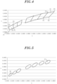
- the plurality of color temperature ranges may have a rectangular shape on the color coordinate system.
- the color temperature range may have a plurality of vertices with a first coordinate P1, a second coordinate P2, a third coordinate P3, and a fourth coordinate P4.
- the first coordinate P1 may have an x value that is smaller than the x values of the second coordinate P2 and the third coordinate P3, and a y value that is smaller than the y values of the second coordinate P2, the third coordinate P3, and the fourth coordinate P4, but is not limited thereto.
- the x value of the first coordinate P1 of the first color temperature region S1 may be smaller than the x values of the second coordinate P2, the third coordinate P3, and the fourth coordinate P4.
- the y value of the first coordinate P1 of the first color temperature region S1 may be smaller than the y values of the second coordinate P2, the third coordinate P3, and the fourth coordinate P4.
- the x-value of the first coordinate P1 within the first color temperature region S1 may be approximately 0.4373, and the y-value may be approximately 0.3893.
- the x-value of the second coordinate P2 may be approximately 0.4593, and the y-value may be approximately 0.3944.
- the x-value of the third coordinate P3 may be approximately 0.4813, and the y-value may be approximately 0.4319.
- the x-value of the fourth coordinate P4 may be approximately 0.45623, and the y-value may be approximately 0.4260.
- these values are not limited to the above examples.
- the first light-emitting elements 410 may have an rms value of similarity to natural light (Srms) that is less than 0.9, as will be described later. Through this, the first light-emitting elements 410 may have a spectrum similar to that of sunlight. Further, the x value of the first coordinate P1 of the second color temperature region S2 may be located between the x value of the fourth coordinate P4 and the x value of the second coordinate P2. The y value of the first coordinate P1 of the second color temperature region S2 may be less than the y values of the second coordinate P2, the third coordinate P3, and the fourth coordinate P4.
- the x-value of the first coordinate P1 within the second color temperature region S2 may be approximately 0.3067, and the y-value may be approximately 0.3119.
- the x-value of the second coordinate P2 may be approximately 0.3221, and the y-value may be approximately 0.3255.
- the x-value of the third coordinate P3 may be approximately 0.3205, and the y-value may be approximately 0.3477.
- the x-value of the fourth coordinate P4 may be approximately 0.3026, and the y-value may be approximately 0.3311.
- these values are not limited to the above examples.
- the second light-emitting elements 420 may have an rms value of similarity to natural light (Srms) that is less than 0.9, as will be described later. Through this, the second light-emitting elements 420 may have a spectrum similar to that of sunlight. And the x value of the first coordinate P1 of the first color temperature region S1 may be greater than the x value of the first coordinate P1 of the second color temperature region S2.
- the first light-emitting elements 410 having color coordinates in the first color temperature region S1, may have a higher intensity in the red region compared to the second light-emitting elements 420, which has color coordinates in the second color temperature region S2.
- the intensity in the red region of the mixed light from the first light emitting elements 410 and the second light emitting elements 420 may be compensated, thereby improving the natural light similarity rms (Srms) value in the red light region
- the y value of the first coordinate P1 of the first color temperature region S1 may be greater than the y value of the first coordinate P1 of the second color temperature region S2.
- the first light-emitting elements 410 having color coordinates in the first color temperature region S1, may have a higher intensity in the green region compared to the second light-emitting elements 420, which has color coordinates in the second color temperature region S2.
- the intensity in the green region of the mixed light from the first light emitting elements 410 and the second light emitting elements 420 may be compensated, thereby improving the natural light similarity rms (Srms) value in the green light region
- the second coordinate P2 may have a y value smaller than the y values of the third coordinate P3 and the fourth coordinate P4, and may have an x value greater than the x value of the fourth coordinate P4.
- the x value of the second coordinate P2 of the first color temperature region S1 may be smaller than the x value of the third coordinate P3 and larger than the x values of the fourth coordinate P4 and the first coordinate P1.
- the y value of the second coordinate P2 of the first color temperature region S1 may be smaller than the y values of the third coordinate P3 and the fourth coordinate P4, and larger than the y value of the first coordinate P1.
- the x value of the second coordinate P2 of the second color temperature region S2 may be greater than the x values of the first coordinate P1, the third coordinate P3, and the fourth coordinate P4.
- the y value of the second coordinate P2 of the second color temperature region S2 may be smaller than the y values of the third coordinate P3 and the fourth coordinate P4, and larger than the y value of the first coordinate P1.
- the x value of the second coordinate P2 of the first color temperature region S1 may be greater than the x value of the second coordinate P2 of the second color temperature region S2.
- the first light-emitting elements 410 having color coordinates in the first color temperature region S1, may have a higher intensity in the red region compared to the second light-emitting elements 420, which has color coordinates in the second color temperature region S2.
- the intensity in the red region of the mixed light from the first light emitting elements 410 and the second light emitting elements 420 may be compensated, thereby improving the natural light similarity rms (Srms) value in the red light region.
- the y value of the second coordinate P2 of the first color temperature region S1 may be greater than the y value of the second coordinate P2 of the second color temperature region S2.
- the first light-emitting elements 410 having color coordinates in the first color temperature region S1, may have a higher intensity in the green region compared to the second light-emitting elements 420, which has color coordinates in the second color temperature region S2.
- the intensity in the green region of the mixed light from the first light emitting elements 410 and the second light emitting elements 420 may be compensated, thereby improving the natural light similarity rms (Srms) value in the green light region.
- the third coordinate P3 may have a y value greater than the y values of the first coordinate P1, the second coordinate P2, and the fourth coordinate P4. Further, the third coordinate P3 may have an x value greater than the x values of the first coordinate P1 and the fourth coordinate P4. In other words, the x value of the third coordinate P3 of the first color temperature region S1 may be greater than the x values of the first coordinate P1, the third coordinate P3, and the fourth coordinate P4. The y value of the third coordinate P3 of the first color temperature region S1 may be greater than the y values of the first coordinate P1, the second coordinate P2, and the fourth coordinate P4.
- the x value of the third coordinate P3 of the second color temperature region S2 may be greater than the x values of the first coordinate P1 and the fourth coordinate P4, and smaller than the x value of the third coordinate P3.
- the y value of the third coordinate P3 of the second color temperature region S2 may be greater than the y values of the first coordinate P1, the second coordinate P2, and the fourth coordinate P4.
- the x value of the third coordinate P3 of the first color temperature region S1 may be greater than the x value of the third coordinate P3 of the second color temperature region S2.
- the first light-emitting elements 410 having color coordinates in the first color temperature region S1, may have a higher intensity in the red region compared to the second light-emitting elements 420, which has color coordinates in the second color temperature region S2.
- the intensity in the red region of the mixed light from the first light emitting elements 410 and the second light emitting elements 420 may be compensated, thereby improving the natural light similarity rms (Srms) value in the red light region.
- the y value of the third coordinate P3 of the first color temperature region S1 may be greater than the y value of the third coordinate P3 of the second color temperature region S2.
- the first light-emitting elements 410 having color coordinates in the first color temperature region S1, may have a higher intensity in the green region compared to the second light-emitting elements 420, which has color coordinates in the second color temperature region S2.
- the intensity in the green region of the mixed light from the first light emitting elements 410 and the second light emitting elements 420 may be compensated, thereby improving the natural light similarity rms (Srms) value in the green light region.
- the fourth coordinate P4 may have a y value greater than the y values of the first coordinate P1 and the second coordinate P2, but less than the y value of the third coordinate P3. Further, the fourth coordinate P4 may have an x value smaller than at least one of the x values of the first coordinate P1, the second coordinate P2, and the third coordinate P3. In other words, the x value of the fourth coordinate P4 of the first color temperature region S1 may be greater than the x value of the first coordinate P1 and smaller than the x values of the second coordinate P2 and the third coordinate P3. The y value of the fourth coordinate P4 of the first color temperature region S1 may be greater than the y values of the first coordinate P1 and the second coordinate P2, but smaller than the y value of the third coordinate P3.
- the x value of the fourth coordinate P4 of the second color temperature region S2 may be smaller than the x values of the first coordinate P1, the second coordinate P2, and the third coordinate P3.
- the y value of the fourth coordinate P4 of the second color temperature region S2 may be greater than the y values of the first coordinate P1 and the second coordinate P2, but smaller than the y value of the third coordinate P3.
- the x value of the fourth coordinate P4 of the first color temperature region S1 may be greater than the x value of the fourth coordinate P4 of the second color temperature region S2.
- the first light-emitting elements 410 having color coordinates in the first color temperature region S1, may have a higher intensity in the red region compared to the second light-emitting elements 420, which has color coordinates in the second color temperature region S2.
- the intensity in the red region of the mixed light from the first light emitting elements 410 and the second light emitting elements 420 may be compensated, thereby improving the natural light similarity rms (Srms) value in the red light region.
- the y value of the fourth coordinate P4 of the first color temperature region S1 may be greater than the y value of the fourth coordinate P4 of the second color temperature region S2.
- the first light-emitting elements 410 having color coordinates in the first color temperature region S1, may have a higher intensity in the green region compared to the second light-emitting elements 420, which has color coordinates in the second color temperature region S2.
- the intensity in the green region of the mixed light from the first light emitting elements 410 and the second light emitting elements 420 may be compensated, thereby improving the natural light similarity rms (Srms) value in the green light region.
- the sizes of the plurality of color temperature ranges may be formed differently.
- the sizes of the plurality of color temperature ranges may increase towards the first color temperature region S1.
- the size of the first color temperature region S1 may be larger than that of the second color temperature region S2.
- the distance between the first coordinate P1 and the third coordinate P3 of the plurality of color temperature ranges may increase as it approaches the first color temperature region S1.
- the plurality of color temperature ranges may be arranged such that at least some of them are adjacent to each other.
- the plurality of color temperature ranges may have an elliptical shape on the color coordinate system.
- the light sources within one of these ellipses may have similar colors perceived by the average human eye, resulting in a light emitting device with low color difference.
- Lengths of major axes of the plurality of ellipses may range from 0.0110 to 0.0144, and lengths of minor axes may range from 0.0045 to 0.0066, but is not limited thereto.
- the plurality of color temperature ranges in the second example may be formed smaller than those in the first example.
- the light sources within one of the plurality of ellipses may not only be perceived similarly by the average human eye, but may also be recognized as similar colors by sensitive individuals or when plurality of sources are placed adjacently, thus creating a premium light emitting device.
- the color temperature region of the second example may be positioned within each of the plurality of color temperature regions of the first example.
- the midpoint color coordinate values of the color temperature ranges in the second example may differ from those in the first example.
- the plurality of color temperature ranges of the second example may be tilted at a predetermined angle with respect to the x-axis of the color coordinate system.
- the predetermined angle may be range from 40° to 70°, but is not limited thereto.
- the tilted angles of at least some of the plurality of color temperature regions may be formed differently.
- the tilted angle of the first color temperature region S1 may be formed differently from the tilted angle of the second color temperature region S2. In other words, the angle at which the first color temperature region S1 is tilted may be greater than the angle at which the second color temperature region S2 is tilted.
- the plurality of color temperature regions may be spaced apart from each other. Further, at least some of the plurality of color temperature regions may be formed with different sizes.
- color temperature ranges may be formed as smaller ellipses compared to the color temperature ranges in the second example.
- the color temperature ranges in the third example may be located inside each of the color temperature ranges of the second example.
- the lengths of the major axes of the color temperature ranges may range from 0.0066 to 0.0086, while the lengths of the minor axes thereof may range from 0.0027 to 0.0040. This enables a high quality light emitting device with less chromatic aberration in the color temperature region of the third example than in the second example to be realized.
- the color temperature ranges in the third example may be tilted at a predetermined angle relative to the x axis of the color coordinate system.
- the predetermined angle may range from 40° to 70°.
- the tilt angle of the color temperature ranges in the third example may be the same as that of the second example.
- the tilt angle of the first color temperature region S1 may be greater than that of the second color temperature region S2. This is because the steeper the slope of the color temperature lines on the black body locus, the greater the tilt angle may be, allowing for the selection of regions with similar color temperatures and the implementation of high quality light emitting devices with reduced chromatic aberration.
- the plurality of color temperature regions may be spaced apart from each other. Further, at least some of the sizes of the plurality of color temperature regions may be formed differently.
- the substrate 430 may support the plurality of first light emitting elements 410 and second light emitting elements 420.
- the substrate 430 may be made of alumina, quartz, calcium zirconate, forsterite, SiC, graphite, fused silica, mullite, cordierite, zirconia, beryllia, aluminum nitride, low-temperature co-fired ceramic (LTCC), paper phenolic, or epoxy resin combined with glass or paper.
- LTCC low-temperature co-fired ceramic
- the substrate 430 may be a printed circuit board (PCB) that includes metal wiring.
- PCB printed circuit board
- the power distributor 500 may apply power input from an outside to at least one of the first light emitting element 410 and the second light emitting element 420. In addition, the power distributor 500 may adjust the power applied to the first light emitting element 410 and the power applied to the second light emitting element 420. The intensity of light of the first light emitting element 410 and the second light emitting element 420 can be varied by the power distributor 500, and through this, the correlated color temperature can be adjusted. Additionally, the power distributor 500 can adjust the intensity of light from the first light-emitting element 410 and the second light-emitting element 420 to tune the mixed light's natural light similarity rms (Srms) to a value smaller than 0.9. This enables the implementation of a light-emitting device 1 that emits light similar to natural light.
- Srms mixed light's natural light similarity rms
- the intensity of light from the first light emitting element 410 may increase, while the power applied to the second light emitting element 420 may decrease, resulting in a reduction in the intensity of light from the second light emitting element 420.
- the correlated color temperature of the light emitter 400 may be closer to the first light emitting element 410 than to the second light emitting element 420, and may have a correlated color temperature that is relatively distant from that of the second light emitting element 420.
- the average color coordinate values of the first light emitting element 410 and the second light emitting element 420 may be positioned within the first color temperature region S1 or closer to the first color temperature region S1 than to the second color temperature region S2.
- the intensity of light from the first light emitting element 410 may reduce, while the power applied to the second light emitting element 420 increases, resulting in an increase in the intensity of light from the second light emitting element 420.
- the correlated color temperature of the light emitter 400 may be closer to the second light emitting element 420 than to the first light emitting element 410, and may have a correlated color temperature that is relatively distant from that of the first light emitting element 410.
- the average color coordinate values of the first light emitting element 410 and the second light emitting element 420 may then be positioned within the second color temperature region S2or closer to the second color temperature region S2than to the first color temperature region S1.
- the light emitter 400 may have a correlated color temperature between the first light emitting element 410 and the second light emitting element 420. More preferably, if the light amount of the first light emitting element 410 and the light amount of the second light emitting element 420 are the same, the light emitter 400 that emits 3900K may have a correlated color temperature of 3900K to 4500K. Further, the average of the color coordinate values of the first light emitting element 410 and the second light emitting element 420 may be located between or in the center of the first color temperature region S1 and the second color temperature region S2.
- the power distributor 500 may control the power amount of the first light emitting element 410 and the second light emitting element 420 by adjusting a time period during which power is supplied.
- the time period during which power is supplied may be adjusted by increasing or decreasing the duty cycle during which power is applied. That is, when the duty cycle increases, the amount of power increases and the light amount of the first light emitting element 410 and the second light emitting element 420 increases, and when the duty cycle decreases, the amount of power decreases and the light amount of the first light emitting element 410 and the second light emitting element 420 decreases.
- the intensity of light of the first light emitting element 410 and the second light emitting element 420 may be varied by the power distributor 500.
- the duty cycle applied to the first light emitting element 410 increases, the intensity of light of the first light emitting element 410 increases, and the duty cycle applied to the second light emitting element 420 decreases to reduce the amount of power, so that the intensity of light of the second light emitting element 420 may be reduced, and the light emitter 400 may have a correlated color temperature closer to that of the first light emitting element 410 than that of the second light emitting element 420.
- the duty cycle applied to the first light emitting element 410 decreases, the amount of power decreases to decrease the intensity of light from the first light emitting element 410, and the duty cycle applied to the second light emitting element 420 increases to increase the power amount, so that the intensity of light of the second light emitting element 420 may increase, and the light emitter 400 may have a correlated color temperature closer to that of the second light emitting element 420 than that of the first light emitting element 410, and may have a correlated color temperature that is relatively distant from that of the first light emitting element 410.
- the light emitter 400 may have a correlated color temperature between the first light emitting element 410 and the second light emitting element 420, and more preferably a correlated color temperature of 3900K to 4500K.
- the controller 600 may control one or more of the light emitter 400 and the power distributor 500 to generate light from the light emitter 400.
- the controller 600 may adjust the intensity of light from the plurality of first light emitting elements 410 and the plurality of second light emitting elements 420 so that the average color coordinate values of the plurality of first light emitting elements 410 and the plurality of second light emitting elements 420 are located within any one of the plurality of color temperature regions.
- the controller 600 may control the power distributor 500 to adjust the intensity of light from the plurality of first light emitting elements 410 and second light emitting elements 420.
- the controller 600 may control the intensities of the plurality of first light emitting elements 410 and the plurality of second light emitting elements 420 so that the average of color coordinate values of the plurality of light emitting elements move from one of the first color temperature region S1 and the second color temperature region S2 towards the other of the first color temperature region S1 and the second color temperature region S2. Further, the controller 600 may increase the light intensity of the plurality of first light emitting elements 410 and decrease the light intensity of the plurality of second light emitting elements 420 such that the average of the color coordinate values of the plurality of first light emitting elements 410 and second light emitting elements 420 is moved toward the first color temperature region S1.
- the controller 600 may decrease the light intensity of the plurality of first light emitting elements 410 and increase the light intensity of the plurality of second light emitting elements 420 such that the average of the color coordinate values of the plurality of first light emitting elements 410 and second light emitting elements 420 moves toward the second color temperature region S2.
- controller 600 may equalize the intensities of light from the plurality of first light emitting elements 410 and the plurality of second light emitting elements 420, placing the average color coordinate values of the plurality of light-emitting elements at the center between the first color temperature region S1 and the second color temperature region S2.
- the controller 600 may form the light intensity of the plurality of first light emitting elements 410 and the light intensity of the plurality of second light emitting elements420 to be the same such that the average of the color coordinate values of the plurality of first light emitting elements 410 and second light emitting elements 420 is disposed in one of the plurality of color temperature regions and is centered in the first color temperature region S1 and the second color temperature region S2.
- a microphone 700 may be additionally arranged.
- the microphone 700 may receive sounds occurring in the space where the light emitting device 1 is installed.
- sounds inputted through the microphone 700 may include various sounds such as movie audio or music.
- the controller 600 may control the light emitter 400 to adjust the correlated color temperature of the light emitter 400.
- the controller 600 may adjust the color temperature of the light emitter 400 based on the volume of the sound inputted through the microphone 700.
- the light emitter 400 may be controlled by the controller 600 such that when the sound volume increases, the correlated color temperature of the light emitter 400 increases, and when the sound volume decreases, the correlated color temperature of the light emitter 400 decreases.
- a light emitting device 1 according to a second embodiment of the present disclosure will be described.
- the controller 600 controls the light emitter 400 such that the natural light similarity rms (Srms) satisfies a ranging from 0.001 to 0.9, and this difference will be explained in detail.
- the light emitter 400 and the light emitting device 1 may have spectral flux similar to natural light.
- the light emitter 400 which has the spectral flux similar to natural light, may be configured so that the Srms for the similarity to natural light according to wavelength in Equation 1 satisfies a range of 0.001 to 0.9.
- the Srms refers to the natural light similarity rms.
- the natural light similarity rms (Srms) may be close to 0, indicating a high similarity to natural light.
- the natural light similarity rms (Srms) exceeds 0.9, the similarity to the natural light spectrum may decrease, leading to lower color rendering and a decline in light quality.
- Srms drops below 0.001, the design complexity may increase significantly beyond what users can perceive.
- Equation 1 a is a wavelength selected within the range of 200 nm or more and less than 500 nm, and b is a wavelength selected within the range of 500 nm or more and less than 900 nm.
- L c (x k ) is the normalized spectral radiant flux of the light emitted from the light emitter 400.
- ref c (x k ) is the normalized spectral radiant flux of natural light from the natural light spectrum.
- the normalized spectral radiant flux of natural light may be obtained based on the highest radiant flux value in the natural light spectrum.
- the normalized spectral radiant flux that is, L1(x k ) of the emitted light may be obtained by normalizing the spectral radiant flux such that a normalized luminous flux of the natural light obtained by multiplying the spectral radiant flux of the natural light normalized from the spectrum of the light emitter light emitter 400 by an area multiplied by a weighting factor B(x k ), which accounts for human visual sensitivity, is equal to the area obtained by multiplying the spectral radiant flux of the light emitter 400 by an area multiplied by the weighting factor which accounts for human visual sensitivity.
- the luminous flux of ref c (x k ) and the luminous flux of L c (x k ) are normalized to have the same value.
- Equation 1 represents the natural light similarity 5 ( x k ) according to the wavelength.
- the light emitter 400 may include at least one light-emitting element with a peak wavelength. This peak wavelength may be within the blue wavelength range of 400 nm to 480 nm. By increasing the intensity of the blue region, it is possible to improve the natural light similarity rms (Srms) in the blue light region. Additionally, to further enhance the natural light similarity in the blue region, the light emitter may include at least two light emitting elements with different peaks. In this case, the difference in peak wavelengths between the two light-emitting elements can be 10 nm or less, allowing improvement in natural light similarity without increasing chromatic aberration.
- the light emitter may include a wavelength converter containing at least two types of phosphors.
- These phosphors can include trace amounts of luminescent ions in the host materials, with the luminescent ions differing between the two phosphors.
- the wavelength converter may include at least one type of green or yellow phosphor.
- Such phosphors can include YAG, LSN, LYSN, SiAlON, GYAG, LuAG, ZnZ, or Gd3Ga5O12, with Ce3+ as a possible luminescent ion.
- the wavelength converter may include at least one type of red phosphor.
- red phosphors include (Ca,Sr)AlSiN3+, La2O2S+, (La,Sr)AlO3, or CaAl2O4, with Eu2+ or Eu3+ used as luminescent ions.
- the difference in peak wavelengths between the two types of red phosphors can be 20 nm or more, increasing the intensities in both short-wavelength and long-wavelength red regions and improving Srms.
- green and yellow two types of phosphors, one green and one yellow, can be used. These green and yellow phosphors may have peak differences of 10 nm or more, improving the intensities in the green and yellow regions and further enhancing Srms.
- the natural light similarity of the light emitting device 1 and light emitter 400 may have different natural light similarity in each wavelength regions.
- the similarity to natural light in the range of 430 nm to 470 nm may be relatively lower compared to other regions (excluding 430 nm to 470 nm). At this time, the natural light similarity may take a value between -2.5 and 1. Additionally, the natural light similarity in the range of 530 nm to 680 nm may be higher than in other regions (excluding 530 nm to 680 nm) and is preferably between -1.5 and 1. If the natural light similarity is higher in the long wavelength region of 530 nm to 680 nm than in the blue region, it may have a high color rendering index for red or yellow regions, thus implementing a high quality light emitting device. Moreover, if the light in the blue region from 430 nm to 470 nm is higher than that of natural light, the user may feel that it is bright even for similar light intensity, so it can be applied to security lights, etc.
- natural light similarity may vary with different correlated color temperatures. For example, the higher the correlated color temperature, the higher the natural light similarity. In other words, the lower the correlated color temperature, the lower the natural light similarity may be.
- the light emitter 400 if the first light emitting element 410 has a lower correlated color temperature than the second light emitting element 420, the natural light similarity of the first light emitting element 410 may have a lower natural light similarity than the second light emitting element 420.
- the light emitter 400 may have a natural light similarity equal to or higher than the first light emitting element 410 and a lower natural light similarity than the second light emitting element 420.
- the natural light similarity between 430 nm and 730 nm may be such that the first light emitting element 410 has a lower correlated color temperature than the second light emitting element 420, and the natural light similarity between 430 nm and 730 nm of the light emitter 400 may have a natural light similarity higher than or equal to the first light emitting element 410 and may have a natural light similarity lower than or equal to the second light emitting element 420.
- the natural light similarity Srms1 of the first light emitting element 410 may be higher than the natural light similarity Srms2 of the second light emitting element 420, as shown in Equation 3 below.
- the higher natural light similarity may have a lower Srms value.
- Equation 3 Srms1 is the natural light similarity rms of the first light emitting element 410 and Srms2 is the natural light similarity rms of the second light emitting element 420.
- the difference between the natural light similarity rms Srms1 of the first light emitting element 410 and the natural light similarity rms Srms2 of the second light emitting element 420 may be less than or equal to 0.2 as shown in the following Equation 4. This may ensure that the mixed light natural light similarity rms (Srms) value of the mixed light from the first light-emitting elements 410 and the second light-emitting elements 420 does not exceed 0.9, which may thereby reduce the design complexity of the light-emitting device 1.
- the natural light similarity (Srms(sum)) of the mixed light of the first light emitting element 410 and the second light emitting element 420 may be lower than the natural light similarity of the first light emitting element 410 or the natural light similarity of the second light emitting element 420, as shown in Equations 5 and 6 below.
- Equation 5 Srms(sum) is the natural light similarity of the mixed light.
- a difference between the natural light similarity Srms(sum) of the mixed light and the natural light similarity of either the first light emitting element 410 or the second light emitting element 420 may be less than or equal to 0.2, as shown in the Equation 7 below. This may ensure that the mixed light natural light similarity rms (Srms) value of the mixed light from the first light-emitting elements 410 and the second light-emitting elements 420 does not exceed 0.9, which may thereby reduce the design complexity of the light-emitting device 1.
- the lower the color temperature in the first light emitting element 410 and the second light emitting element 420 in the same color region the higher the similarity to natural light.
- the first color temperature region S1 if the first light emitting element 410 is located to the left of the second light emitting element 420, it may have a lower natural light similarity.
- the first light emitting element 410 when the first light emitting element 410 is in a lower region than the second light emitting element 420 in the first color temperature region S1, the first light emitting element 410 may have a lower natural light similarity compared to the second light emitting element 420.
- the mixed light in which the light of the first light emitting element 410 is mixed with the light of the second light emitting element 420 may be located between the color coordinates of the first light emitting element 410 and the second light emitting element 420 in the first color temperature region S1, and the natural light similarity of the mixed light may have a value between the natural light similarities of the first light emitting element 410 and the second light emitting element 420.
- the natural light similarity for each wavelength may have a higher natural light similarity in the region of 510 nm to 630 nm, which is the sensitive region of human vision, and by increasing the natural light similarity in the sensitive region of human vision, the light emitting device with high color reproduction can be realized with minimal impact on light efficiency.
- the natural light similarity in the sensitive region may be higher for the light emitting element with lower color temperatures. Also, the higher the correlated color temperature, the lower the natural light similarity in the sensitive region may be.
- the natural light similarity in the sensitive region of the first light emitting element 410 may have a lower natural light similarity in the sensitive region than the second light emitting element 420.
- the light emitter 400 with mixed light may have the natural light similarity in the sensitive region equal to or higher than that of the first light emitting element 410 and lower than that of the second light emitting element 420.
- the natural light similarity in the sensitive region may not be proportional to the overall natural light similarity.
- the light emitting element with a higher correlated color temperature may have a higher overall natural light similarity than the light emitting element with a lower correlated color temperature, but the natural light similarity in the sensitive region may be higher in the light emitting element with the lower correlated color temperature.
- the first light emitting element 410 may have a higher overall natural light similarity but a lower natural light similarity in the sensitive region compared to the second light emitting element 420. This is because the light emitting element with the relatively higher correlated color temperature requires less light in the long wavelength region than the light emitting device with the lower correlated color temperature, so long wavelength conversion can be done only as needed, thereby improving luminous efficiency
- the standard deviation of the natural light similarity S ( x k ) for each wavelength may be higher for the first light emitting element 410 than for the second light emitting element 420.
- the standard deviation of the natural light similarity for the light emitter 400 may have a value between that of the first light emitting element 410 and the second light emitting element 420, and may be equal to or lower than the first light emitting element 410 and equal to or higher than the second light emitting element 420.
- the Srms value may be lower for the first light emitting element 410 than the second light emitting element 420 in the light emitter 400 when the first light emitting element 410 has a lower correlated color temperature than the second light emitting element 420.
- the second light emitting element 420 may have a higher Srms value than the first light emitting element 410 and may have a light intensity for each wavelength similar to natural light.
- the Srms value of the light emitter 400 may have a Srms value between the first light emitting element 410 and the second light emitting element 420, and more preferably may have a higher Srms value than the first light emitting element 410 and a lower Srms value than the second light emitting element 420.
- Figs. 9 to 13 illustrate the relative spectral flux of natural light for each wavelength.
- the relative spectral flux of natural light at a correlated color temperature of 6500K may be the highest in the range of 440 nm to 480 nm. In other words, the relative spectral flux at 460 nm may peak at 1.
- the relative spectral flux of natural light at a correlated color temperature of 5000K may be the highest between 530 nm and 680 nm. In other words, the relative spectral flux at 550 nm may peak at 1.
- Fig. 9 the relative spectral flux of natural light at a correlated color temperature of 6500K may be the highest in the range of 440 nm to 480 nm. In other words, the relative spectral flux at 460 nm may peak at 1.
- the relative spectral flux of natural light at a correlated color temperature of 5000K may be the highest between 530 nm and 680 nm. In other words, the relative
- the relative spectral flux of natural light for each wavelength at a correlated color temperature of 4000K may be the highest in the range of 700 nm to 750 nm. In other words, the relative spectral flux at 733 nm may peak at 1.
- the relative spectral flux of natural light at a correlated color temperature of 3000K may be the highest in the range of 750 nm to 780 nm. In other words, the relative spectral flux at 780 nm may peak at 1.
- the relative spectral flux of natural light for each wavelength at a correlated color temperature of 2700K may be the highest in the range of 750 nm to 780 nm. In other words, the relative spectral flux may have a peak at 780 nm with a value of 1. As the spectrum of natural light decreases, the wavelength at which the maximum relative spectral flux is formed may increase.
- the controller 600 may control the light emitter 400 so that light is emitted from the light emitter 400.
- the controller 600 may also control the light emitter 400 to emit light that satisfies the Srms value defined in Equation 1 ranging from 0.001 to 0.9. This may be used to generate light similar to sunlight.
- the controller 600 may control the light emitter 400 based on input data received from a terminal.
- the input data may include one or more of color coordinates, color temperature, location information, weather information, input time value, input date value, and one or more instructions for controlling the light emitting device 1.
- the input data may be entered by a user operating the terminal.
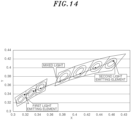
- FIG. 14 there is an example of a color coordinate shift of mixed light of the first light emitting element 410 and the second light emitting element 420 when the second light emitting element 420 has a lower color temperature than the first light emitting element 410.
- the controller 600 may adjust the driving ratio of the first light emitting element 410 and the second light emitting element 420 to form mixed light between the first light emitting element 410 and the second light emitting element 420.
- the natural light similarity of the mixed light may fall between the natural light similarities of the first light emitting element 410 and the second light emitting element 420.
- the controller 600 can adjust the driving ratios of the first light-emitting element 410 and the second light-emitting element 420 so that the Srms value of the mixed light's similarity to natural light becomes lower than the lowest Srms value of 0.9.
- the controller 600 can adjust the driving ratios of multiple light emitting elements to ensure that the mixed light achieves an Srms value lower than the largest Srms value among the light emitting elements with the lowest similarity to natural light.
- a light-emitting device 1 capable of emitting light similar to natural light can be realized.
- the mixed light may have an x value larger than that of the first light emitting element 410 and lower than that of the second light emitting element 420. Additionally, the mixed light may have a y value larger than that of the first light emitting element 410 and lower than that of the second light emitting element 420.
- the first light emitting element 410 may have a color temperature of 6500K.
- the second light emitting element 420 may have a color temperature of 2700K.
- the mixed light may have a color temperature between 2700K and 6500K.
- the first light emitting element 410 may have a lower natural light similarity than the second light emitting element 420.
- the second light emitting element 420 with a lower color temperature may have a higher natural light similarity than the first light emitting element 410 which has a higher natural light similarity in the sensitive region between 510 nm and 630 nm. Furthermore, the natural light similarity of the mixed light for each wavelength in the sensitivity region may fall between the natural light similarities of the first light emitting element 410 and the second light emitting element 420. In one wavelength region, the natural light similarity of the mixed light may be higher than that of the first light emitting element 410 and lower than that of the second light emitting element 420. In one wavelength region, the natural light similarity of the mixed light may be lower than that of the first light emitting element 410 and higher than that of the second light emitting element 420.
- the natural light similarity of the mixed light in the sensitivity region of 510 nm to 630 nm may be higher than that of both the first light emitting element 410 and the second light emitting element 420, it is possible to enhance the natural light similarity without increasing the amount of phosphor used by utilizing two or more light emitting elements, thereby reducing production complexity.
- the controller 600 may control the light intensity of the first light emitting element 410 and the second light emitting element 420 based on time-light intensity correlation information.
- the controller 600 may also store light intensity data for adjusting the light intensity of the first light emitting element 410 and the second light emitting element 420.
- the light intensity data may include a first adjustment value for determining the intensity of the first light emitting element 410 and a second adjustment value for determining the intensity of the second light emitting element 420.
- the first adjustment value may be a power applied to the first light emitting element 410 to cause the first light emitting element 410 to emit light.
- the second adjustment value may be a power applied to the second light emitting element 420 to cause the second light emitting element 420 to emit light.
- the controller 600 may control the power distributor 500 based on the first adjustment value and the second adjustment value. In other words, the controller 600 may control the power distributor 500 such that the first adjustment value is applied to the first light emitting element 410 and the second adjustment value is applied to the second light emitting element 420.
- Table 1 is an exemplary table of the correlation information between the first and second control values based on color temperature.
- color Light Source Remark 1 2 Warm Cool Module Noon (Reference) 0% 100% cool white ⁇ 30% 70% Daylight 60% 40% Neutral white ⁇ 90% 10% Sunset (Start)/Sunrise (End) 100% 0% Warm white
- the first adjustment value applied to the first light emitting device may be decreased and the second adjustment value applied to the second light emitting device may be increased as the color temperature increases.
- the intensity of the light of the second light emitting element 420 increases, so that the proportion of the light of the second light emitting element 420 in the light of the light emitter 400 increases, and the proportion of the light of the first light emitting element 410 decreases, and the correlated color temperature of the light emitter 400 may have a correlated color temperature closer to the second light emitting element 420 than to the first light emitting element 410, and may have a higher color temperature than the first light emitting element 410.
- the second adjustment value may decrease and the first adjustment value may increase.
- the intensity of the light of the first light emitting element 410 increases, so that the proportion of the light of the second light emitting element 420 in the light of the light emitter 400 decreases, and the proportion of the light of the first light emitting element 410 increases, and the correlated color temperature of the light emitter 400 may have a correlated color temperature closer to the first light emitting element 410 than the second light emitting element 420, and may have a correlated color temperature lower than the second light emitting element 420.
- the light emitting device 1 can generate light with a correlated color temperature similar to that of natural light, and can emit light whose spectrum of the light flux for each wavelength similar to that of natural light with the same correlated color temperature.
- the light flux for each wavelength emitted by the light emitting device 1 can be formed to satisfy the Srms value between 0.001 and 1, as expressed in Equation 1.
- the Srms value may be between 0.05 and 0.9 to have a significant effect on human visual sensitivity.
- the Srms value when the light emitter 400 emits light with a correlated color temperature of 6500K, the Srms value can be formed between 0.05 and 0.70. When the light emitter 400 emits light with a correlated color temperature of 4000K, the Srms value can also be between 0.05 and 0.70. When the light emitter 400 emits light with a correlated color temperature of 2700K, the Srms value can be formed between 0.40 and 0.75.
Landscapes
- Engineering & Computer Science (AREA)
- General Engineering & Computer Science (AREA)
- Led Device Packages (AREA)
- Electroluminescent Light Sources (AREA)
Priority Applications (1)
| Application Number | Priority Date | Filing Date | Title |
|---|---|---|---|
| PCT/KR2024/019408 WO2025116657A1 (ko) | 2023-12-01 | 2024-11-29 | 발광장치 |
Applications Claiming Priority (3)
| Application Number | Priority Date | Filing Date | Title |
|---|---|---|---|
| US202363605034P | 2023-12-01 | 2023-12-01 | |
| US202463684503P | 2024-08-19 | 2024-08-19 | |
| US18/963,184 US20250185138A1 (en) | 2023-12-01 | 2024-11-27 | Light emitting device |
Publications (2)
| Publication Number | Publication Date |
|---|---|
| EP4565040A2 true EP4565040A2 (de) | 2025-06-04 |
| EP4565040A3 EP4565040A3 (de) | 2025-09-03 |
Family
ID=93741319
Family Applications (1)
| Application Number | Title | Priority Date | Filing Date |
|---|---|---|---|
| EP24216147.9A Pending EP4565040A3 (de) | 2023-12-01 | 2024-11-28 | Lichtemittierende vorrichtung |
Country Status (3)
| Country | Link |
|---|---|
| US (1) | US20250185138A1 (de) |
| EP (1) | EP4565040A3 (de) |
| WO (1) | WO2025116657A1 (de) |
Family Cites Families (3)
| Publication number | Priority date | Publication date | Assignee | Title |
|---|---|---|---|---|
| KR100972634B1 (ko) * | 2008-07-28 | 2010-07-27 | 한국광기술원 | 태양광과 일치하는 색 온도 제어 방법 및 제어장치 |
| CN110382948B (zh) * | 2017-02-28 | 2021-09-21 | 科勒克斯有限责任公司 | 基于阳光的太阳模拟照明 |
| CN109121243B (zh) * | 2017-06-26 | 2020-09-15 | 财团法人工业技术研究院 | 光源装置及显示装置 |
-
2024
- 2024-11-27 US US18/963,184 patent/US20250185138A1/en active Pending
- 2024-11-28 EP EP24216147.9A patent/EP4565040A3/de active Pending
- 2024-11-29 WO PCT/KR2024/019408 patent/WO2025116657A1/ko active Pending
Also Published As
| Publication number | Publication date |
|---|---|
| US20250185138A1 (en) | 2025-06-05 |
| WO2025116657A1 (ko) | 2025-06-05 |
| EP4565040A3 (de) | 2025-09-03 |
Similar Documents
| Publication | Publication Date | Title |
|---|---|---|
| US12381190B2 (en) | Warm dimming LED-filaments and LED-filament lamps | |
| CN102714260B (zh) | 包括光混合物的固态照明装置 | |
| CN112424962B (zh) | 照明装置 | |
| CN102124263B (zh) | 包括光混合的固态照明装置 | |
| US10008484B2 (en) | Solid state light fixtures suitable for high temperature operation having separate blue-shifted-yellow/green and blue-shifted-red emitters | |
| US9241384B2 (en) | Solid state lighting devices with adjustable color point | |
| US9198251B2 (en) | Tunable correlated color temperature LED-based white light source with mixing chamber and remote phosphor exit window | |
| US8884508B2 (en) | Solid state lighting device including multiple wavelength conversion materials | |
| US8664846B2 (en) | Solid state lighting device including green shifted red component | |
| CN101821544B (zh) | 照明装置及制造方法 | |
| US20150359050A1 (en) | Lighting devices with variable gamut | |
| JP5654328B2 (ja) | 発光装置 | |
| US9215761B2 (en) | Solid state lighting devices with color point non-coincident with blackbody locus | |
| JP2002057376A (ja) | Ledランプ | |
| TW201130381A (en) | Solid state lighting apparatus with configurable shunts | |
| EP4565040A2 (de) | Lichtemittierende vorrichtung | |
| US12429175B2 (en) | Lighting apparatus | |
| CN121761262A (zh) | 发光装置 | |
| US20250098055A1 (en) | Light emitting device and system including the same | |
| CN222437701U (zh) | 发光装置 | |
| US20250048803A1 (en) | Light emitting apparatus |
Legal Events
| Date | Code | Title | Description |
|---|---|---|---|
| PUAI | Public reference made under article 153(3) epc to a published international application that has entered the european phase |
Free format text: ORIGINAL CODE: 0009012 |
|
| STAA | Information on the status of an ep patent application or granted ep patent |
Free format text: STATUS: REQUEST FOR EXAMINATION WAS MADE |
|
| 17P | Request for examination filed |
Effective date: 20241128 |
|
| AK | Designated contracting states |
Kind code of ref document: A2 Designated state(s): AL AT BE BG CH CY CZ DE DK EE ES FI FR GB GR HR HU IE IS IT LI LT LU LV MC ME MK MT NL NO PL PT RO RS SE SI SK SM TR |
|
| PUAL | Search report despatched |
Free format text: ORIGINAL CODE: 0009013 |
|
| AK | Designated contracting states |
Kind code of ref document: A3 Designated state(s): AL AT BE BG CH CY CZ DE DK EE ES FI FR GB GR HR HU IE IS IT LI LT LU LV MC ME MK MT NL NO PL PT RO RS SE SI SK SM TR |
|
| RIC1 | Information provided on ipc code assigned before grant |
Ipc: H10H 29/14 20250101AFI20250729BHEP Ipc: H10H 29/851 20250101ALI20250729BHEP |