EP4566460A1 - Dispositif d'extrusion avec au moins deux vis et un compartiment commun - Google Patents
Dispositif d'extrusion avec au moins deux vis et un compartiment commun Download PDFInfo
- Publication number
- EP4566460A1 EP4566460A1 EP23213992.3A EP23213992A EP4566460A1 EP 4566460 A1 EP4566460 A1 EP 4566460A1 EP 23213992 A EP23213992 A EP 23213992A EP 4566460 A1 EP4566460 A1 EP 4566460A1
- Authority
- EP
- European Patent Office
- Prior art keywords
- conveyor
- extruder device
- compression
- viscous material
- feeding section
- Prior art date
- Legal status (The legal status is an assumption and is not a legal conclusion. Google has not performed a legal analysis and makes no representation as to the accuracy of the status listed.)
- Pending
Links
Images



Classifications
-
- A—HUMAN NECESSITIES
- A23—FOODS OR FOODSTUFFS; TREATMENT THEREOF, NOT COVERED BY OTHER CLASSES
- A23P—SHAPING OR WORKING OF FOODSTUFFS, NOT FULLY COVERED BY A SINGLE OTHER SUBCLASS
- A23P30/00—Shaping or working of foodstuffs characterised by the process or apparatus
- A23P30/20—Extruding
-
- A—HUMAN NECESSITIES
- A23—FOODS OR FOODSTUFFS; TREATMENT THEREOF, NOT COVERED BY OTHER CLASSES
- A23P—SHAPING OR WORKING OF FOODSTUFFS, NOT FULLY COVERED BY A SINGLE OTHER SUBCLASS
- A23P20/00—Coating of foodstuffs; Coatings therefor; Making laminated, multi-layered, stuffed or hollow foodstuffs
- A23P20/20—Making of laminated, multi-layered, stuffed or hollow foodstuffs, e.g. by wrapping in preformed edible dough sheets or in edible food containers
-
- B—PERFORMING OPERATIONS; TRANSPORTING
- B33—ADDITIVE MANUFACTURING TECHNOLOGY
- B33Y—ADDITIVE MANUFACTURING, i.e. MANUFACTURING OF THREE-DIMENSIONAL [3D] OBJECTS BY ADDITIVE DEPOSITION, ADDITIVE AGGLOMERATION OR ADDITIVE LAYERING, e.g. BY 3D PRINTING, STEREOLITHOGRAPHY OR SELECTIVE LASER SINTERING
- B33Y10/00—Processes of additive manufacturing
-
- B—PERFORMING OPERATIONS; TRANSPORTING
- B33—ADDITIVE MANUFACTURING TECHNOLOGY
- B33Y—ADDITIVE MANUFACTURING, i.e. MANUFACTURING OF THREE-DIMENSIONAL [3D] OBJECTS BY ADDITIVE DEPOSITION, ADDITIVE AGGLOMERATION OR ADDITIVE LAYERING, e.g. BY 3D PRINTING, STEREOLITHOGRAPHY OR SELECTIVE LASER SINTERING
- B33Y30/00—Apparatus for additive manufacturing; Details thereof or accessories therefor
-
- B—PERFORMING OPERATIONS; TRANSPORTING
- B65—CONVEYING; PACKING; STORING; HANDLING THIN OR FILAMENTARY MATERIAL
- B65G—TRANSPORT OR STORAGE DEVICES, e.g. CONVEYORS FOR LOADING OR TIPPING, SHOP CONVEYOR SYSTEMS OR PNEUMATIC TUBE CONVEYORS
- B65G15/00—Conveyors having endless load-conveying surfaces, i.e. belts and like continuous members, to which tractive effort is transmitted by means other than endless driving elements of similar configuration
- B65G15/28—Conveyors with a load-conveying surface formed by a single flat belt, not otherwise provided for
-
- A—HUMAN NECESSITIES
- A23—FOODS OR FOODSTUFFS; TREATMENT THEREOF, NOT COVERED BY OTHER CLASSES
- A23P—SHAPING OR WORKING OF FOODSTUFFS, NOT FULLY COVERED BY A SINGLE OTHER SUBCLASS
- A23P20/00—Coating of foodstuffs; Coatings therefor; Making laminated, multi-layered, stuffed or hollow foodstuffs
- A23P20/20—Making of laminated, multi-layered, stuffed or hollow foodstuffs, e.g. by wrapping in preformed edible dough sheets or in edible food containers
- A23P20/25—Filling or stuffing cored food pieces, e.g. combined with coring or making cavities
- A23P2020/253—Coating food items by printing onto them; Printing layers of food products
-
- B—PERFORMING OPERATIONS; TRANSPORTING
- B65—CONVEYING; PACKING; STORING; HANDLING THIN OR FILAMENTARY MATERIAL
- B65G—TRANSPORT OR STORAGE DEVICES, e.g. CONVEYORS FOR LOADING OR TIPPING, SHOP CONVEYOR SYSTEMS OR PNEUMATIC TUBE CONVEYORS
- B65G2201/00—Indexing codes relating to handling devices, e.g. conveyors, characterised by the type of product or load being conveyed or handled
- B65G2201/02—Articles
- B65G2201/0202—Agricultural and processed food products
Definitions
- the present invention relates to an extruder device for 3D printing a viscous material, in particular plant-based foodstuff material.
- Additive manufacturing is not only a potential application for the hard tech industry like automotive, aerospace and robotics, but it is also a feasible alternative to produce plant-based seafood and meat, as it can easily recreate the texture and the mouthfeel of animal products.
- a classical way of producing foodstuff via additive manufacturing is by means of 3D printing via syringe/piston systems, for which a cartridge is used. These systems are however limited to small range of materials and designs, such as chocolate and dough. A mass production of foodstuff cannot be achieved with such systems.
- WO2023021148 shows a device for 3D printing for printing foodstuff material.
- the device comprises an inlet, a screw and an outlet. It can be seen that products have to be 3D printed one at a time and as such it is also difficult to implement a mass production of foodstuff with this device.
- an extruder device for 3D printing a viscous material, in particular plant-based foodstuff material
- the extruder device comprises at least two compression screws, which are arranged within a common compartment, wherein the common compartment comprises a nozzle for each compression screw, a feeding section for feeding the viscous material to the at least two compression screws and a compression section located between the feeding section and the nozzles for compressing viscous material towards the nozzles.
- the inventive extruder device has the advantage that it allows for a mass production of 3D printing a viscous material since the extruder device allows to print at least two products, e.g., artificial salmon fillets, at the same time. Moreover, the extruder device allows a continuous additive manufacturing process because the feeding section acts as a hopper for storing the viscous material. The extruder device therefore allows for continuous additive manufacturing of multiple 3D structures over a long period of time with little to no manual intervention.
- the extruder device is therefore especially suited for a use in a manufacturing line where multiple structures can be produced in parallel.
- the device can furthermore be controlled in an efficient manner as only the compression screws need to be driven in order to start, pause or stop the 3D printing process of multiple products.
- the device furthermore has the additional advantage that it can be easily disassembled for cleaning and maintenance because all compression screws are only enclosed by one single element, i.e., the common compartment, which at the same time embodies a voluminous storage container in the feeding section and a compression section for all compression screws.
- the swift removal of the single common compartment also has the advantage that all compression screws can quickly and simultaneously be made accessible. Thereby, screws can quickly be replaced by other types of compression screws, if needed, or simply be removed for cleaning.
- the device comprises a screw barrel for each compression screw, wherein the screw barrels are located in the compression zone.
- the screw barrels usually have a cylindrical or conical inner shape and therefore allow for a tight enclosure of the compression screws. If the screw barrels can be removed from the common compartment and exchanged for screw barrels with different inner diameters, it is also possible to adjust the compression and adapt the extruder device to different use cases. When exchanging a screw, the screw barrel can be exchanged at the same time. However, the screw barrels could also be integrally formed in the common compartment. In other embodiments, no screw barrels are provided.
- the common compartment embodies a voluminous storage container in the feeding section.
- the volume of the feeding section should be higher than in the compression section.
- the feeding section has a larger cross-sectional area than the compression section, preferably in all sections along the longitudinal direction of the screw, optionally with the exception on the junction of the feeding section and the compression section, where the cross-sectional area could be the same. If screw barrels are used, the cross-sectional area of the feeding section will be larger than the cross-sectional area of the compression section even at said junction.
- the feeding section is configured as a tapered reservoir. This on the one hand helps to achieve a feeding section with a high volume but on the other hand also facilitates the flow of viscous material towards the compression section.
- a tapered reservoir also has the advantage that the top side of the tapered reservoir may be left open, such that there can be provided a relatively large opening for refilling viscous fluid into the common reservoir.
- the feeding section is configured to hold at least 10 1, 20 1, 35 1 or 50 1 of viscous material.
- the extruder device is configured to print six salmon fillets in parallel, said specification of the feeding section allow to print 500 fillets a day with a minimum of refill operations.
- the feeding section may be configured such that viscous material filled into the feeding section is in fluid connection with all compression screws. This has the additional advantage that viscous material filled into the common compartment is evenly distributed to all compression screws such that it is very unlikely to occur that viscous material is provided to one compression screw but not to another.
- the compression screws print the same structures but in different material, in which case at least one partition wall may be located within the common compartment such that viscous material filled into the feeding section on one side of the partition wall is in fluid connection with only a subsection of the compression screws.
- the screws within the common compartment can be arranged in an arbitrary manner, for example in a linear manner along a straight or curved line or even in an m x n array, where m and n are at least 2 or at least 3.
- the amount of compression screws can in principle be chosen arbitrarily but may be limited by a power of the motor if the compression screws are driven by a common motor.
- each compression screw is driven by a different motor.
- all compression screws are driven by a common motor, which is linked to the compression screws via a linkage. This firstly has the advantage that less structural components have to be used but also ensures that all compression screws are driven uniformly with the same speed. Also the control of the device is simplified as there will be only one motor which has to be driven. In other embodiments, at least two of the screws could be driven by different motors, for example when individual compression screws or subsets of compression screws are to be driven independently or when the compression screws would provide too much resistance when driven by a common motor.
- the extruder device described above may be used for a 3D printing system, in which case the 3D printing system usually comprises at least one first extruder device as described above and a conveyor.
- the extruder device is arranged such that all nozzles of the extruder device print the viscous material onto the conveyor.
- the extruder device comprises six compression screws, it will be possible to print six structures onto the same conveyor at the same time.
- the extruder device is static and the conveyor is capable of moving in three orthogonal directions. In this case, the conveyor may be moved in such a way that the structures are printed in three dimensions.
- the conveyor moves within a horizontal x, y plane while the extruder device prints several structures (according to the number of compression screws) to print a first layer of the structure, then the conveyor moves in the vertical z-direction such that a second layer of the structure may be printed onto the first layer, etc.
- the extruder device could print onto a normal, e.g., static, 3D printing platform.
- a static extruder device is preferred because the feeding section of the common compartment acts as a storage unit of the extruder device and depending on the fill level of the common compartment, the weight of the extruder device may vary significantly, which complicates driving the extruder device.
- the conveyor has a conveyor support and a conveyor belt at least partially covering the conveyor support, wherein the conveyor belt is configured to move structures located thereon in a first horizontal direction and the conveyor support is preferable also configured to be moved in a second horizontal direction normal to the first horizontal direction, in particular via a spindle drive, and especially preferably also in a vertical direction.
- the conveyor belt has the advantage that the structures can be advances in a first direction while printing, but also to move structures off the conveyor after they have been fully printed. In other embodiments, however, it is possible to provide a conveyor without a conveyor belt, for example when the conveyor comprises a beltless but movable 3D printing platform.
- the 3D printing system may further comprise a second extruder device, wherein the second extruder device is arranged such that all nozzles of the extruder device also print the viscous material onto the conveyor.
- the conveyor may then be controlled such that a partial structure printed by the first extruder device is moved underneath the second extruder device, which prints at least another layer onto the partial structure.
- complex structures with many layers of different materials may be printed, for example salmon fillets having protein layers and fat layers. It is also possible that three or more extruder devices may print onto the same conveyor to print even more complex structures.
- the conveyor may have a limited size such that the conveyor is only located under the first extruder (and not under the second extruder) when the first extruder device prints and is only located under the second extruder (and not under the first extruder) when the second extruder device prints.
- This embodiment is suited for printing layers of different materials with a light-weight conveyor.
- the conveyor has such a size that the two extruder devices could print onto the conveyor at the same time, for example even with the same material, which could be used for an efficient upscaling.
- extruder devices and systems comprising at least one extruder device and a conveyor are especially suited for upscaling.
- This allows to construct an entire manufacturing line comprising at least two 3D printing systems as mentioned above and a main conveyor, wherein the two at least two 3D printing systems are configured to unload printed viscous materials onto the main conveyor, and the conveyors and the main conveyors are preferable operated such that when unloading structures from the conveyors onto the main conveyor, the unloaded structures do not collide with structures already placed on the main conveyor.
- the manufacturing line may also be further automatized by providing at least one reservoir for storing the viscous fluid and a pipe system connecting the at least one reservoir with at least two common compartments.
- the reservoir allows an automatized or at least semi-automatized refilling of the common compartments of the extruder devices in the manufacturing line.
- the pipe system may contain valves for selectively refilling common compartments.
- there may be a control unit connected to at least two or preferably extruder devices of the manufacturing line, especially to one or more motors driving the compression screws, and preferably also at least one of the following components: at least one or all conveyors, the main conveyor, at least one valve of the pipe system.
- Figure 1 shows an extruder device 1 for 3D printing a viscous material, in particular plant-based foodstuff material.
- the viscous material could, for example, have a viscosity of 3000 Pas to 18000 Pas.
- the viscous material is foodstuff material such as for the production of meat/seafood alternatives, pasta, dysphagia applications, doughs or personalized food.
- the viscous material could also be clay or concrete.
- the extruder device 1 is not limited to specific use cases.
- the extruder device 1 comprises six compression screws 2, which are located within a common compartment 3.
- the invention is not restricted to six compression screws 2 but there could be two or more compression screws 2 located inside the common compartment 3.
- the compression screws 2 are usually arranged in a linear manner along a straight line (as shown in figures 1 to 3 ), but other configurations are possible too.
- the compression screws 2 could be arranged in an array with at least two compression screws 2 per line of the array and at least two compression screws 2 per row of the array, or linearly along a curved line, instead of a straight line as shown.
- the compression screws 2 may each comprise a screw shaft 4 and a screw winding 5.
- the screw winding 5 can generally be of an arbitrary shape and chosen depending on the viscous material and the desired texture of the foodstuff to be printed.
- the screw winding 5 can be continuous or interrupted, single flight or multi flight, and also have a varying shape over its length.
- the screw winding 5 usually has a cylindrical outer shape upon rotation but could also have a conical outer shape upon rotation.
- the screw winding 5 could be integrally formed on the screw shaft 4 or detachably mounted thereon.
- the compression screws 2 each define an axis of rotation (rotational axis), which runs through the screw shaft 4 and screw winding 5, respectively.
- the rotational axes of all compression screws 2 of the extruder device 1 are usually in parallel. In some embodiments it is also possible to use compression screws 2 without a dedicated screw shaft 4.
- the common compartment 3 comprises a nozzle 6 for each compression screw 2.
- the nozzles 6 each allow a passing of viscous material from the inside of the common compartment 3 to the outside pf the common compartment 3 and define the shape of the extrudate which is being printed. All nozzles 6 can each be configured in the same way or differently to provide different textures of the printed foodstuff material for each nozzle 6, for example.
- the common compartment 3 is composed of two different sections, namely a feeding section FS and a compression section CS.
- the feeding section FS is the zone where the viscous material is fed into the extruder device 1 and stored.
- the compression section CS is the zone where the viscous material is being compressed into a closed area to build up the pressure needed for printing when rotating the compression screws 2.
- the feeding section FS comprises at least one opening O for feeding viscous material into the common compartment 3.
- the opening O could simply be embodied by designing the common compartment 3 without a cover.
- the opening O could also be embodied by a through hole through a side wall or a cover of the common compartment 3.
- the nozzles 6 are arranged such that they are located on one side of the compression section CS, e.g., a bottom of the common compartment 3.
- the compression section CS is in turn located between the feeding section FS and the nozzles 6.
- Such a setup allows to introduce the viscous matter through the opening into the common compartment 3, more precisely into the feeding section FS.
- the viscous matter is transported from the feeding section FS to the compression section CS and from there through the nozzles 6 onto a substrate such as a conveyor (see below).
- the screw winding 5 is at least partially located inside the compression section CS.
- the screw winding 5 extends through the whole compression section CS, i.e., from the nozzle 6 to at least the junction between the compression section CS and the feeding section FS.
- the screw winding 5 can also extend at least partially through the feeding section FS, which may improve the transport of viscous material from the feeding section FS to the compression section CS.
- a screw barrel 7 may be located in the compression section CS.
- the screw barrels 7 are arranged in such a way that one compression screw 2 is located inside each screw barrel 7.
- the inner diameter of the screw barrel 7 may substantially be the same as the outer diameter of the screw 2 or may be slightly larger than the outer diameter of the compression screw 2 to allow for a clearance or to allow for a predefined compression rate, considering that the compression may be reduced if there is more clearance.
- the inner diameter of the screw barrel 7 may be up to 1%, up to 5% or up to 10% larger than the outer diameter of the screw 2. Other relationships of the diameters are possible too, depending on the viscous material, for example.
- the compression screws 2 usually have a cylindrical outer shape upon rotation, in which case also the screw barrels 7 usually have a cylindrical inner shape. If the compression screws 2 have a conical outer shape upon rotation, the screw barrels 7 usually have a conical inner shape.
- the screw barrels 7 may be individual elements, which are inserted into the common compartment 3, as is shown in figure 1 . In this way, the screw barrels 7 may be manufactured from a different material than the common compartment 3. In other embodiments, the screw barrels 7 might also be integrally formed with the common compartment 3. In the shown embodiment, the volume in the feeding section FS is common to all compression screws 2 while the screw barrels 7 provide for separated volumes for each compression screw 2. In other embodiments, the screw barrels 7 may also be omitted or connected in such a way that the volume in the compression section CS is common to all compression screws 2.
- viscous material filled into the feeding section FS is in fluid connection with all compression screws 2.
- the extruder device 1 will print multiple structures of the same material.
- a first viscous material may be provided to one or more compression screws 2 on one side of the partition wall and a second viscous material may be provided to one or more compression screws 2 on the other side of the partition wall.
- the feeding section FS and the compression section CS may also differ from one another in the cross-sectional area.
- the term "cross-sectional area" here refers to a cross section in a plane normal to the longitudinal direction (rotational axis) of the compression screw 2.
- the feeding section FS should have a relatively high storage volume when compared to the volume within the compression section CS, which should be relatively small for achieving the compression effect.
- a cross-sectional area of the feeding section FS, on at least one point or on all points along the longitudinal direction of the compression screw 2 should be higher than the cross-sectional area of the compression section FS along any point of the longitudinal direction of the compression screw 2.
- the feeding section FS can comprise at least 10 1, 20 1, 35 1, or 50 1 (liters) of viscous material. The volume of the feeding section FS may be adjusted depending on the structure to be produced.
- the cross-sectional area of the compression section CS is substantially uniform along the longitudinal direction of the compression screw 2.
- the cross-sectional area of the compression section CS would be defined by the inner diameter of the screw barrels 7 and the amount of screw barrels 7.
- the cross-sectional area of the feeding section FS is usually varying along the longitudinal direction of the compression screws 2 as is shown in figures 1 and 3 .
- the feeding section FS has the shape of a tapered reservoir, specifically the shape of a cropped triangular prism. In other words, three of the side surfaces are substantially vertical and one side surface is slanted with respect to a vertical plane.
- the bottom side of the feeding section FS connects to the compression section CS and the top side of the feeding section FS is coverless and embodies the opening O.
- the compression screws 2 extend through the opening O towards a linkage 9 or motor 10 (see below).
- tapered reservoirs are possible too, for example when two of the side surfaces opposite to each other or all four side surfaces are slanted with respect to a vertical plane.
- Non-tapered reservoirs are possible too, for example when the feeding section FS has a cubic shape.
- connection plates could be provided between the side walls of the compression section CS and the side walls of the feeding section FS to allow for an enlarged cross-sectional area of the feeding section FS with respect to the compression section CS.
- each compression screw 2 may be provided with a gear 8 on the screw shaft 4 on the side of the compression screw 2 located opposite of the nozzle 6.
- the compression screws 2 can be coupled via the gear 8 to a linkage 9 having complementary gear elements.
- the linkage 9 transmits the rotational movement via the gear 8 to the compression screw 2 such that the viscous material can be compressed in the compression section CS and ejected via the nozzle 6.
- the motor 10 may be an electric stepper motor which allows precise and controlled motion via a control software of the extruder device 1 to provide the extrusion needed for printing.
- the transmission (comprising linkage 9 and gears 8) may comprise a bevel gear system with a 1:1 ratio, which means that for one rotation of the motor the compression screws 2 are making one rotation as well. However, a different ratio may be chosen depending on the use.
- each compression screw 2 may be equipped with a gear 8 and linked to the linkage 9, the motor 10 may be configured to drive all compression screws 2 at the same time, i.e., the linkage 9 transmits the rotational movement via the gears 8 to all compression screws 2 at the same time.
- the motor 10 thus drives all compression screws 2 at the same time and the compression screws 2 may not be rotated individually.
- each compression screw 2 could be provided with its own motor 10, which could couple to the gear 8, for example. In this embodiment, no linkage 9 would be necessary. It is to be understood that other embodiments for driving the compression screws 2 are possible too, for example by omitting or replacing the gears 8, linkage 9 and/or motor 10 with similar structures.
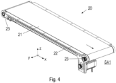
- the extruder device 1 may be used in conjunction with a conveyor 20 as shown in figure 4 .
- the conveyor 20 has such a size that all nozzle 6 can print onto the conveyor 20 at the same time.
- the extruder device 1 is usually statically arranged and the conveyor 20 may move along three preferably orthogonal directions x, y, z such that three-dimensional structures can be printed via the static nozzles 6.
- the x-axis and the y-axis usually lie in a horizontal plane, while the z-axis may be a vertical direction.
- the conveyor 20 may comprise a conveyor belt 21, which is located on a conveyor support 22 and moved by means of two rollers 23 to transport printed structures in the x-direction.
- the rollers 23 may be driven by an electric stepper motor controlled precisely with the printer software, providing the rotation speed and torque needed to run the belt smoothly and accurately.
- a tensioner can be provided, which is designed to tension the conveyor belt 21 to avoid any sliding of the conveyor belt 21 from the roller 23. The more tension is added, the more friction between the roller 23 and the conveyor belt 21 is occurring, allowing a good transmission from the roller 23 to the conveyor belt 21.
- the conveyor belt 21 may be provided for two purposes. Firstly, to advance a structure during printing in the x-direction, i.e., while viscous material is ejected through the nozzle 6, the conveyor belt 21 may be moved in the x-direction to print a structure that is elongated in the x-direction. Secondly, the conveyor belt 21 may move the structures off the conveyor 20 after they are fully printed onto a first support area SA1 (which may also be a further conveyor, see figure 8 ). Thereafter, the conveyor belt 21 will be empty and the extruder device 1 may start printing new structures.
- SA1 which may also be a further conveyor, see figure 8
- FIG. 5 shows the conveyor belt 21 on the conveyor support 22 as shown in figure 4 .
- this conveyor 20 comprises a frame 24, on which the conveyor support 22 is mounted movably in the y-direction.
- one or more spindles 25 may be provided, which run in the y-direction and engage with a bearing of the conveyor support 22 such that upon a rotation of the spindle 25, the conveyor support 22 and thus also the structures on the conveyor support 22 (or the conveyor belt 21, respectively), move in the y-direction.
- a corresponding drive can be implemented in numerous ways, e.g., also as a spindle drive.
- the conveyor 20 described above can however also be configured in different ways, e.g., without the conveyor belt 21 if the conveyor support 22 is movable in the x-direction by other means. Also, if the extruder device 1 is movable in one or more directions, it is not necessary to move the conveyor 20 in the corresponding direction. For example, if the extruder device 1 is movable in the y- direction and z-direction, the conveyor support 22 of figure 4 may be arranged statically such that the conveyor 20 only facilitates a movement of printed structures in the x-direction via the conveyor belt 21. It is also possible to provide no movement in one of the directions x, y and/or z at all, for example if linear structures or one-layer structures are to be manufactured.
- extrusion devices 1 or lines of compression screws 2 are then arranged with an offset in the y-direction and there is no offset in the x-direction and z-direction, for example.
- the offset in the y-direction is such that conveyor support 22 may move from a first position P1 under the first extrusion device 1 ( figure 6 ) to a second position P2 under the second extrusion device 1 ( figure 7 ).
- an offset in the x-direction could be possible too.
- the extrusion devices 1 are filled with different viscous materials, of example orange protein in one extrusion device 1 and white fat in the other extrusion device 1, differently layered structures can be manufactured.
- the conveyor support 22 may move between positions P1 and P2 back and forth to allow for a printing of complex structures. It is also possible to arrange more than two extrusion devices 1 in a manner as shown above to print structures with three or more materials. However, in other embodiments the extrusion devices 1 could also print onto the conveyor 20 at the same time, for example if the conveyor is larger in the y-direction as shown in figures 6 and 7 . Here, the extrusion devices 1 could also be filled with the same viscous material.
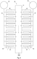
- a manufacturing line 30 can be formed by combining a plurality of systems 40, each comprising an least one extrusion device 1 and a conveyor 20.
- the conveyors 20 of the systems 40 each unload printed structures onto a main conveyor 31, which therefore corresponds to the first support area SA1 of figure 4 .
- the main conveyor 31 can also comprise a conveyor belt (not shown in detail) to transport structures onto a second support area SA2.
- Systems 40 comprising an extrusion device 1 and a conveyor 20 can be arranged on both sides of the main conveyor 31, as is shown, or alternatively only on one side of the main conveyor 31.
- the conveyors 20 and the main conveyor 31 are operated such that when unloading products from the conveyors 20 onto the main conveyor 31, the unloaded structures do not collide with structures already placed on the main conveyor 31.
- the drives of all conveyors 20 and the drive of the main conveyor 31 can be connected to a single control unit.
- This control unit, or a different control unit, may also control be connected to all motors 10 of the systems 40 and also control movement in y-directions and z-directions for printing the structures.
- figure 8 shows that two reservoirs 32 for storing the viscous fluid can be used to provide viscous material to the extruder devices 1.
- the reservoirs 32 contain the same viscous material.
- one or more than two reservoirs 32 could be employed to deliver viscous material to the extruder devices 1.
- a pipe system 33 can be utilized, which connects the reservoir 32 to one or more extruder devices 1, e.g., by having a pipe of the pipe system 33 connected to or extending into the opening O.
Landscapes
- Engineering & Computer Science (AREA)
- Chemical & Material Sciences (AREA)
- Manufacturing & Machinery (AREA)
- Materials Engineering (AREA)
- Life Sciences & Earth Sciences (AREA)
- Food Science & Technology (AREA)
- Polymers & Plastics (AREA)
- Mechanical Engineering (AREA)
Priority Applications (2)
| Application Number | Priority Date | Filing Date | Title |
|---|---|---|---|
| EP23213992.3A EP4566460A1 (fr) | 2023-12-04 | 2023-12-04 | Dispositif d'extrusion avec au moins deux vis et un compartiment commun |
| US18/817,648 US20250176606A1 (en) | 2023-12-04 | 2024-08-28 | Extruder device with at least two screws and a common compartment |
Applications Claiming Priority (1)
| Application Number | Priority Date | Filing Date | Title |
|---|---|---|---|
| EP23213992.3A EP4566460A1 (fr) | 2023-12-04 | 2023-12-04 | Dispositif d'extrusion avec au moins deux vis et un compartiment commun |
Publications (1)
| Publication Number | Publication Date |
|---|---|
| EP4566460A1 true EP4566460A1 (fr) | 2025-06-11 |
Family
ID=89076070
Family Applications (1)
| Application Number | Title | Priority Date | Filing Date |
|---|---|---|---|
| EP23213992.3A Pending EP4566460A1 (fr) | 2023-12-04 | 2023-12-04 | Dispositif d'extrusion avec au moins deux vis et un compartiment commun |
Country Status (2)
| Country | Link |
|---|---|
| US (1) | US20250176606A1 (fr) |
| EP (1) | EP4566460A1 (fr) |
Citations (5)
| Publication number | Priority date | Publication date | Assignee | Title |
|---|---|---|---|---|
| WO2020136383A1 (fr) * | 2018-12-27 | 2020-07-02 | Kraft Foods Schweiz Holding Gmbh | Procédé et appareil d'impression 3d et produits obtenus à partir de celui-ci |
| WO2022076368A1 (fr) * | 2020-10-05 | 2022-04-14 | Frito-Lay North America, Inc. | Impression 3d d'aliments à l'échelle commerciale |
| WO2023007050A1 (fr) * | 2021-07-27 | 2023-02-02 | Cocuus System Iberica, S.L. | Dispositif d'extrusion d'aliments |
| WO2023021148A1 (fr) | 2021-08-18 | 2023-02-23 | Revo Foods Gmbh | Tête d'impression 3d ayant une extrudeuse à vis |
| CN116584682A (zh) * | 2023-05-24 | 2023-08-15 | 西南大学 | 一种3d打印的旋转式双喷头机构 |
Family Cites Families (2)
| Publication number | Priority date | Publication date | Assignee | Title |
|---|---|---|---|---|
| US5450984A (en) * | 1994-04-29 | 1995-09-19 | K-Tron Technologies, Inc. | Material feeding apparatus |
| US20240208154A1 (en) * | 2022-12-22 | 2024-06-27 | International Business Machines Corporation | Continuous 3d printing with conveyor belt |
-
2023
- 2023-12-04 EP EP23213992.3A patent/EP4566460A1/fr active Pending
-
2024
- 2024-08-28 US US18/817,648 patent/US20250176606A1/en active Pending
Patent Citations (5)
| Publication number | Priority date | Publication date | Assignee | Title |
|---|---|---|---|---|
| WO2020136383A1 (fr) * | 2018-12-27 | 2020-07-02 | Kraft Foods Schweiz Holding Gmbh | Procédé et appareil d'impression 3d et produits obtenus à partir de celui-ci |
| WO2022076368A1 (fr) * | 2020-10-05 | 2022-04-14 | Frito-Lay North America, Inc. | Impression 3d d'aliments à l'échelle commerciale |
| WO2023007050A1 (fr) * | 2021-07-27 | 2023-02-02 | Cocuus System Iberica, S.L. | Dispositif d'extrusion d'aliments |
| WO2023021148A1 (fr) | 2021-08-18 | 2023-02-23 | Revo Foods Gmbh | Tête d'impression 3d ayant une extrudeuse à vis |
| CN116584682A (zh) * | 2023-05-24 | 2023-08-15 | 西南大学 | 一种3d打印的旋转式双喷头机构 |
Also Published As
| Publication number | Publication date |
|---|---|
| US20250176606A1 (en) | 2025-06-05 |
Similar Documents
| Publication | Publication Date | Title |
|---|---|---|
| CA2406937C (fr) | Appareil pour produire des denrees alimentaires a double couche | |
| US20160106142A1 (en) | Additive Manufacturing for Producing Edible Compositions | |
| CN100409773C (zh) | 食品材料供给方法及装置 | |
| US20250176606A1 (en) | Extruder device with at least two screws and a common compartment | |
| US5010807A (en) | Ravioli machine | |
| JP2012016344A (ja) | 食品製造装置及び食品製造方法 | |
| JP4274569B2 (ja) | 食品素材の押し出し方法及びその装置 | |
| Raiapaksha et al. | Design and development of pump based chocolate 3D printer | |
| US12201120B2 (en) | Movable mould member for moulding food products | |
| WO2015000037A1 (fr) | Procédé et distributeur pour distribuer une substance fluide | |
| US2031386A (en) | Printing and depositing mechanism | |
| US20100209545A1 (en) | Apparatus for releasing food slurry along predetermined course | |
| JP7314208B2 (ja) | 食品材料の吐出装置 | |
| KR100884617B1 (ko) | 분상체용 포장기계의 분배 투입장치 | |
| JPS589676A (ja) | 球状食品成形装置 | |
| KR102937989B1 (ko) | 3d 식품 프린터 | |
| CN218662449U (zh) | 一种馅料定量分料机 | |
| CN217446617U (zh) | 一种定量分馅机 | |
| KR20120110224A (ko) | 분상체용 포장기계의 분배 투입장치 | |
| US20250049050A1 (en) | Device and method for forming a product that imitates properties of meat, poultry, fish, seafood, dairy products, or products derived therefrom | |
| CN120436349A (zh) | 用于食品打印机的喷嘴 | |
| KR20230085113A (ko) | 3차원 식용 제품의 제조를 위한 시스템 및 방법 | |
| CN114467996A (zh) | 一种盘式彩虹胚涂抹机 | |
| EP0135100A2 (fr) | Un dispositif pour le transfert de quantités mesurées et formées d'un produit pâteux | |
| HK1059193A (en) | An apparatus for producing food products in two layers |
Legal Events
| Date | Code | Title | Description |
|---|---|---|---|
| PUAI | Public reference made under article 153(3) epc to a published international application that has entered the european phase |
Free format text: ORIGINAL CODE: 0009012 |
|
| STAA | Information on the status of an ep patent application or granted ep patent |
Free format text: STATUS: THE APPLICATION HAS BEEN PUBLISHED |
|
| AK | Designated contracting states |
Kind code of ref document: A1 Designated state(s): AL AT BE BG CH CY CZ DE DK EE ES FI FR GB GR HR HU IE IS IT LI LT LU LV MC ME MK MT NL NO PL PT RO RS SE SI SK SM TR |
|
| STAA | Information on the status of an ep patent application or granted ep patent |
Free format text: STATUS: REQUEST FOR EXAMINATION WAS MADE |
|
| 17P | Request for examination filed |
Effective date: 20251110 |