EP4566558A1 - Électrode de référence dédiée à l'estimation de proximité de tissu de cathéter - Google Patents
Électrode de référence dédiée à l'estimation de proximité de tissu de cathéter Download PDFInfo
- Publication number
- EP4566558A1 EP4566558A1 EP24217631.1A EP24217631A EP4566558A1 EP 4566558 A1 EP4566558 A1 EP 4566558A1 EP 24217631 A EP24217631 A EP 24217631A EP 4566558 A1 EP4566558 A1 EP 4566558A1
- Authority
- EP
- European Patent Office
- Prior art keywords
- distal
- ring electrode
- reference ring
- electrode
- functional electrodes
- Prior art date
- Legal status (The legal status is an assumption and is not a legal conclusion. Google has not performed a legal analysis and makes no representation as to the accuracy of the status listed.)
- Pending
Links
Images


Classifications
-
- A—HUMAN NECESSITIES
- A61—MEDICAL OR VETERINARY SCIENCE; HYGIENE
- A61B—DIAGNOSIS; SURGERY; IDENTIFICATION
- A61B18/00—Surgical instruments, devices or methods for transferring non-mechanical forms of energy to or from the body
- A61B18/04—Surgical instruments, devices or methods for transferring non-mechanical forms of energy to or from the body by heating
- A61B18/12—Surgical instruments, devices or methods for transferring non-mechanical forms of energy to or from the body by heating by passing a current through the tissue to be heated, e.g. high-frequency current
- A61B18/14—Probes or electrodes therefor
- A61B18/1492—Probes or electrodes therefor having a flexible, catheter-like structure, e.g. for heart ablation
-
- A—HUMAN NECESSITIES
- A61—MEDICAL OR VETERINARY SCIENCE; HYGIENE
- A61B—DIAGNOSIS; SURGERY; IDENTIFICATION
- A61B5/00—Measuring for diagnostic purposes; Identification of persons
- A61B5/24—Detecting, measuring or recording bioelectric or biomagnetic signals of the body or parts thereof
- A61B5/25—Bioelectric electrodes therefor
- A61B5/279—Bioelectric electrodes therefor specially adapted for particular uses
- A61B5/28—Bioelectric electrodes therefor specially adapted for particular uses for electrocardiography [ECG]
- A61B5/283—Invasive
- A61B5/287—Holders for multiple electrodes, e.g. electrode catheters for electrophysiological study [EPS]
-
- A—HUMAN NECESSITIES
- A61—MEDICAL OR VETERINARY SCIENCE; HYGIENE
- A61B—DIAGNOSIS; SURGERY; IDENTIFICATION
- A61B5/00—Measuring for diagnostic purposes; Identification of persons
- A61B5/24—Detecting, measuring or recording bioelectric or biomagnetic signals of the body or parts thereof
- A61B5/316—Modalities, i.e. specific diagnostic methods
- A61B5/318—Heart-related electrical modalities, e.g. electrocardiography [ECG]
- A61B5/367—Electrophysiological study [EPS], e.g. electrical activation mapping or electro-anatomical mapping
-
- A—HUMAN NECESSITIES
- A61—MEDICAL OR VETERINARY SCIENCE; HYGIENE
- A61B—DIAGNOSIS; SURGERY; IDENTIFICATION
- A61B18/00—Surgical instruments, devices or methods for transferring non-mechanical forms of energy to or from the body
- A61B2018/00053—Mechanical features of the instrument of device
- A61B2018/00214—Expandable means emitting energy, e.g. by elements carried thereon
- A61B2018/0022—Balloons
-
- A—HUMAN NECESSITIES
- A61—MEDICAL OR VETERINARY SCIENCE; HYGIENE
- A61B—DIAGNOSIS; SURGERY; IDENTIFICATION
- A61B18/00—Surgical instruments, devices or methods for transferring non-mechanical forms of energy to or from the body
- A61B2018/00053—Mechanical features of the instrument of device
- A61B2018/00214—Expandable means emitting energy, e.g. by elements carried thereon
- A61B2018/00267—Expandable means emitting energy, e.g. by elements carried thereon having a basket shaped structure
-
- A—HUMAN NECESSITIES
- A61—MEDICAL OR VETERINARY SCIENCE; HYGIENE
- A61B—DIAGNOSIS; SURGERY; IDENTIFICATION
- A61B18/00—Surgical instruments, devices or methods for transferring non-mechanical forms of energy to or from the body
- A61B2018/00315—Surgical instruments, devices or methods for transferring non-mechanical forms of energy to or from the body for treatment of particular body parts
- A61B2018/00345—Vascular system
- A61B2018/00351—Heart
-
- A—HUMAN NECESSITIES
- A61—MEDICAL OR VETERINARY SCIENCE; HYGIENE
- A61B—DIAGNOSIS; SURGERY; IDENTIFICATION
- A61B18/00—Surgical instruments, devices or methods for transferring non-mechanical forms of energy to or from the body
- A61B2018/00571—Surgical instruments, devices or methods for transferring non-mechanical forms of energy to or from the body for achieving a particular surgical effect
- A61B2018/00577—Ablation
-
- A—HUMAN NECESSITIES
- A61—MEDICAL OR VETERINARY SCIENCE; HYGIENE
- A61B—DIAGNOSIS; SURGERY; IDENTIFICATION
- A61B18/00—Surgical instruments, devices or methods for transferring non-mechanical forms of energy to or from the body
- A61B2018/00636—Sensing and controlling the application of energy
- A61B2018/00642—Sensing and controlling the application of energy with feedback, i.e. closed loop control
-
- A—HUMAN NECESSITIES
- A61—MEDICAL OR VETERINARY SCIENCE; HYGIENE
- A61B—DIAGNOSIS; SURGERY; IDENTIFICATION
- A61B18/00—Surgical instruments, devices or methods for transferring non-mechanical forms of energy to or from the body
- A61B2018/00636—Sensing and controlling the application of energy
- A61B2018/00666—Sensing and controlling the application of energy using a threshold value
-
- A—HUMAN NECESSITIES
- A61—MEDICAL OR VETERINARY SCIENCE; HYGIENE
- A61B—DIAGNOSIS; SURGERY; IDENTIFICATION
- A61B18/00—Surgical instruments, devices or methods for transferring non-mechanical forms of energy to or from the body
- A61B2018/00636—Sensing and controlling the application of energy
- A61B2018/00773—Sensed parameters
- A61B2018/00875—Resistance or impedance
-
- A—HUMAN NECESSITIES
- A61—MEDICAL OR VETERINARY SCIENCE; HYGIENE
- A61B—DIAGNOSIS; SURGERY; IDENTIFICATION
- A61B18/00—Surgical instruments, devices or methods for transferring non-mechanical forms of energy to or from the body
- A61B18/04—Surgical instruments, devices or methods for transferring non-mechanical forms of energy to or from the body by heating
- A61B18/12—Surgical instruments, devices or methods for transferring non-mechanical forms of energy to or from the body by heating by passing a current through the tissue to be heated, e.g. high-frequency current
- A61B18/14—Probes or electrodes therefor
- A61B2018/1405—Electrodes having a specific shape
- A61B2018/1407—Loop
-
- A—HUMAN NECESSITIES
- A61—MEDICAL OR VETERINARY SCIENCE; HYGIENE
- A61B—DIAGNOSIS; SURGERY; IDENTIFICATION
- A61B18/00—Surgical instruments, devices or methods for transferring non-mechanical forms of energy to or from the body
- A61B18/04—Surgical instruments, devices or methods for transferring non-mechanical forms of energy to or from the body by heating
- A61B18/12—Surgical instruments, devices or methods for transferring non-mechanical forms of energy to or from the body by heating by passing a current through the tissue to be heated, e.g. high-frequency current
- A61B18/14—Probes or electrodes therefor
- A61B2018/1467—Probes or electrodes therefor using more than two electrodes on a single probe
-
- A—HUMAN NECESSITIES
- A61—MEDICAL OR VETERINARY SCIENCE; HYGIENE
- A61B—DIAGNOSIS; SURGERY; IDENTIFICATION
- A61B90/00—Instruments, implements or accessories specially adapted for surgery or diagnosis and not covered by any of the groups A61B1/00 - A61B50/00, e.g. for luxation treatment or for protecting wound edges
- A61B90/04—Protection of tissue around surgical sites against effects of non-mechanical surgery, e.g. laser surgery
- A61B2090/0409—Specification of type of protection measures
- A61B2090/0427—Prevention of contact
-
- A—HUMAN NECESSITIES
- A61—MEDICAL OR VETERINARY SCIENCE; HYGIENE
- A61B—DIAGNOSIS; SURGERY; IDENTIFICATION
- A61B90/00—Instruments, implements or accessories specially adapted for surgery or diagnosis and not covered by any of the groups A61B1/00 - A61B50/00, e.g. for luxation treatment or for protecting wound edges
- A61B90/06—Measuring instruments not otherwise provided for
- A61B2090/064—Measuring instruments not otherwise provided for for measuring force, pressure or mechanical tension
- A61B2090/065—Measuring instruments not otherwise provided for for measuring force, pressure or mechanical tension for measuring contact or contact pressure
Definitions
- the present disclosure relates generally to invasive medical probes, and particularly to estimation of proximity of catheters to tissue.
- U.S. Patent Application Publication 2023/0112251 describes a system including a catheter and a processor.
- the catheter includes a distal-end assembly coupled to a distal end of a shaft for insertion into a cavity of an organ of a patient, the distal-end assembly including (i) one or more functional electrodes configured to be placed in contact with wall tissue of the cavity and (ii) a reference electrode configured to be placed in the cavity but not in contact with the wall tissue.
- the reference electrode is disclosed as an electrode that is positioned within an inner volume defined by the distal-end assembly. Selectively placing the reference electrode within that inner volume provides distancing the reference electrode from the tissue wall.
- the processor is configured to (i) estimate one or more impedances between one or more of the functional electrodes and the reference electrode, and (ii) based on the impedances, determine, for at least a functional electrode from among the one or more functional electrodes, whether the functional electrode is in physical contact with the wall tissue.
- Wall tissue of a cavity of an organ of a patient can be electroanatomically mapped and/or ablated using a catheter having multiple functional electrodes fitted at an expandable distal-end assembly of the catheter.
- the physician may manipulate an expanded distal-end assembly to have the electrodes contact chamber walls to acquire and/or apply electrical signals.
- a proximity scale may use arbitrary units (e.g., an index ranging from 1 to 10) or can be given in physical units of distance.
- a processor can be configured to estimate the proximity using calibrated proximity data by translating impedance to electrode-tissue proximity.
- One way to calculate the TPI is to: (i) identify from the monitored imbalances a range of the lowest and highest values recorded over time, (ii) normalize the monitored impedances according to the range, and (iii) relate the normalized range to a scale of TPI.
- TPI is a binary value, e.g., 0 for no touch, and 1 for touch.
- One way to calculate the binary TPI is to: (i) identify from the monitored imbalances a range of the lowest and highest values recorded over time, (ii) set a threshold according to the range, and (iii) define a corresponding normalized threshold according to the normalized range of TPI. For example, a normalized threshold value of 0.7 above which the reported TPI is 1, and below, zero.
- the system measures an impedance between a pair of electrodes, one of which is a reference electrode that is in the blood pool and the other a functional electrode. Based on this measurement a processor runs an algorithm to determine the proximity of the functional electrode to the tissue. Minimal impedance occurs when the functional electrode is well within the blood pool of a cardiac chamber, while maximal impedance occurs when the functional electrode is in full contact, e.g., engagement with a threshold pressure. The impedance reading is continuous between these two limits.
- a reference electrode is positioned within an inner volume of an expandable distal assembly as described herein above.
- the inventors have found that improved sensitivity may be achieved by directing a larger portion of the electric field outwardly across the volume that may potentially include a portion of the tissue wall. To this end, they propose to locate a reference electrode externally to the inner volume of the expandable distal assembly at a location where the reference electrode will be spaced away from any contact with tissue.
- Examples of the present disclosure that are described herein provide a ring electrode, selectively positioned at a base of the expandable assembly and in close proximity to the expandable portion of the distal assembly.
- the base of the expandable assembly being part of the assembly, is the element to which the assembly is coupled to a distal end of a shaft of the catheter, i.e., the ring reference electrode is distal to the shaft. Since the ring reference electrode is at the base of the expandable assembly, it typically does not touch the tissue wall while the expandable assembly is in an expanded state. Further to that, the ring reference electrode diameter is about 2-5 mm in diameter while the distal end assembly in its expanded state is sphere-like with a diameter of about 20-30 mm. Due to this significant difference in diameter, positioning the reference electrode at the base of the distal end assembly has the assembly acting as a spacer that spaces the reference electrode away from the tissue.
- the path of the electric potential between such a ring reference electrode and a functional electrode is sensitive to tissue proximity, as both the plurality of functional electrodes and the reference ring electrode are external to an inner volume defined by the expandable assembly. Proximity is therefore based on monitoring an increase in impedance over time for each functional electrode.
- the electric field path through the inner-facing side of the functional electrodes can be eliminated and/or reduced by coating the inner-facing side of the spline with an insulating coating, as described in Fig. 2 .
- an additional guard ring protrudes further than the reference ring electrode, and is configured to act as a spacer that blocks contact between the reference ring and tissue wall. This way the guard ring reduces instances of touch, e.g., near a ridge of a cardiac chamber anatomy.
- the distal end assembly is essentially one piece made from a nitinol tube
- the base section as a proximal section of the distal end assembly, is electrically conductive.
- the reference ring electrode is electrically insulated from the nitinol base.
- the reference electrode may touch tissue. This can be identified by comparing the electrical signals from all of the functional electrodes. If all of the signals from all of the functional electrodes signify touch (e.g., all simultaneously show an increase in impedance), it is most likely caused by the reference electrode touching tissue, since some functional electrodes should always be immersed in a blood pool. Therefore, in this case, the system discards this reading.
- Fig. 1 is a schematic, pictorial illustration of a catheter-based electroanatomical (EA) mapping and ablation system 10, in accordance with an example of the present disclosure.
- System 10 is configured to determine, e.g., prior to performing diagnostics and/or ablation, whether a given functional electrode 26 of a plurality of functional electrodes 26 of a basket catheter 14 has sufficient contact with (or proximity to) tissue, or is immersed in blood pool 33 of a cardiac chamber.
- System 10 includes one or more catheters which are percutaneously inserted, by physician 24, through the patient's vascular system into a chamber or vascular structure of a heart 12.
- a delivery sheath catheter is inserted into the left or right atrium near a desired location in heart 12.
- one or more catheters can be inserted into the delivery sheath catheter to arrive at the desired location.
- the one or more catheters may include catheters dedicated for sensing intracardiac electrogram (IEGM) signals, catheters dedicated to ablating and/or catheters dedicated to both sensing and ablating.
- An example basket catheter 14 that is configured for sensing IEGM is illustrated herein.
- physician 24 brings a basket type of expandable distal-end assembly 28 (also called hereinafter “expandable distal-end assembly 28") fitted on a shaft 44 of catheter 14 into contact with the heart wall for sensing a target site in heart 12.
- physician 24 similarly brings the distal end of an ablation catheter to a target site for ablating.
- catheter 14 is an exemplary catheter that includes one, and preferably multiple, functional electrodes 26 optionally distributed over a plurality of splines 22 at expandable distal-end assembly 28 and configured to sense IEGM signals.
- Catheter 14 additionally includes a proximal position sensor 29 (e.g., TAS 29 comprising three EMCs) embedded in a distal end 46 of shaft 44 near expandable distal end assembly 28, to track the position of the distal end of expandable distal end assembly 28.
- position sensor 29 is a magnetic-based position sensor that includes magnetic coils for sensing three-dimensional (3D) position.
- Distal end 46 of shaft 44 may comprise an amplifying circuit configured to amplify the output from the three EMCs of sensor 29.
- Magnetic position sensor 29 is operated together with an external location pad 25 that includes a plurality of magnetic coils 32 configured to generate magnetic fields in a predefined working volume. Using the operation with external location pad 25 (each EMC using a different frequency), the processor can determine the position of each EMC 29 on a coordinate system of the position tracking system.
- System 10 includes one or more electrode patches 38 positioned for skin contact on patient 23 to establish a location reference for location pad 25 as well as impedance-based tracking of functional electrodes 26.
- impedance-based tracking electrical current is directed toward electrodes 26 and sensed at electrode skin patches 38, such that the location of each electrode can be triangulated via electrode patches 38.
- Real-time orientation of expandable distal end assembly 28 of catheter 14 can be calculated from tracked locations of electrodes 26. This relative orientation is manifested by an angle formed between distal end 46 and a longitudinal axis 42 of expandable assembly 28 (to a distal edge 16 of the assembly).
- Catheter 14 is configured to acquire electrical signals indicative of proximity of any given functional electrode 26 to the wall tissue of heart 12.
- a signal generator 35 is configured to generate an AC signal between a reference ring electrode 17 and each of the functional electrodes 26.
- the processor measures corresponding impedances between each functional electrode 26 and reference ring electrode 17 located on a base 37 of the expandable distal-end assembly 28 externally to an inner volume 77 defined by the splines of assembly 28. Having the electrical path between each functional electrode 26 and reference ring electrode 17 to assembly 28 improves the sensitivity of the measurement to tissue proximity.
- Reference ring electrode 17 is positioned on a base of the assembly 28 in a place that avoids contact with the tissue wall while the distal end assembly 28 is in an expanded state, as further described in Fig. 2 .
- a recorder 11 displays electrograms 21 captured with body surface ECG electrodes 18 and intracardiac electrograms (IEGM) captured with functional electrodes 26 of catheter 14.
- Recorder 11 may include pacing capability for pacing the heart rhythm and/or may be electrically connected to a standalone pacer.
- System 10 may include an ablation energy generator 50 that is adapted to conduct ablative energy to a subset of the plurality of electrodes 26 at the distal assembly 28 of catheter 14 configured for ablating.
- Energy produced by ablation energy generator 50 may include, but is not limited to, radiofrequency (RF) energy or pulsed-field ablation (PFA) energy, including monopolar or bipolar high-voltage DC pulses that may be used to effect irreversible electroporation (IRE), or combinations thereof.
- RF radiofrequency
- PFA pulsed-field ablation
- IRE irreversible electroporation
- Patient interface unit (PIU) 30 is configured to establish electrical communication between catheters, electrophysiological equipment, power supply and a workstation 55 for controlling the operation of system 10.
- Electrophysiological equipment of system 10 may include, for example, multiple catheters, location pad 25, body surface ECG electrodes 18, electrode patches 38, ablation energy generator 50, and recorder 11.
- PIU 30 additionally includes processing capability for implementing real-time computations of catheter locations and for performing ECG calculations.
- Workstation 55 includes memory 57, processor unit 56 with memory or storage with appropriate operating software loaded therein, and user interface capability. Workstation 55 may provide multiple functions, optionally including (i) modeling endocardial anatomy in three-dimensions (3D) and rendering the model or anatomical map 20 for display on a display device 27, (ii) displaying on display device 27 activation sequences (or other data) compiled from recorded electrograms 21 in representative visual indicia or imagery superimposed on the rendered anatomical map 20, (iii) displaying real-time location and orientation of multiple catheters within the heart chamber, and (iv) displaying on display device 27 sites of interest such as places where ablation energy has been applied.
- One commercial product embodying elements of system 10 is available as the CARTO TM 3 System, available from Biosense Webster, Inc., 31A Technology Drive, Irvine, CA 92618.
- Fig. 1 describes a basket assembly
- the disclosed technique can be applied, mutatis mutandis, to an expandable balloon assembly having an expandable membrane, wherein the functional electrodes are disposed over the membrane.
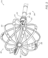
- Fig. 2 is a schematic, pictorial illustration of a basket catheter assembly 281 configured for electrical measurement of the proximity of a functional electrode 226 to cavity wall tissue, in accordance with an example of the present disclosure.
- Basket assembly 281 can be used to implement basket assembly 28 of Fig. 1 above.
- assembly 281 is part of a catheter 214 further comprising a shaft 244 having a distal end 246.
- Distal-end assembly 228 includes a proximal base 227 configured to couple the assembly to a distal end 246 of the shaft 244.
- Basket assembly 281 is realized as an expandable frame comprising multiple splines 222, wherein the functional electrodes 226 are coupled to the splines.
- Splines 22 are each electrically insulated from the environment over most of their area by an insulation layer 262.
- the expandable distal-end assembly 281 When expanded, as shown in Fig. 2 , the expandable distal-end assembly 281 defines an inner volume 277. At the base of the assembly inside volume 277, a far-field electrode 223 is used to remove far-field signals from IEGM signals acquired by electrodes 226.
- the plurality of functional electrodes 226 are at least partially external to the inner volume and are configured to be placed in contact with wall tissue of the cavity.
- a reference ring electrode 217 (such as ring electrode 17 of Fig. 1 ), is located on proximal base 227 of the expandable distal-end assembly 281 and externally to the inner volume 277. The position of the ring shaped electrode 217 over base 227 is set such to avoid contact with tissue wall while the distal end assembly 281 is in an expanded state.
- reference ring electrode 217 is a ring fitted on an external perimeter of the proximal base section 227.
- Reference ring electrode 217 may be disposed over an insulating layer (not shown), for example when base section 227 is electrically conductive (e.g., made of nitinol).
- the proximal base section 227 further comprises a mechanical guard ring 231 that protrudes outwards from the proximal base, i.e., further than reference electrode 227, to prevent reference electrode 227 from contact with wall tissue.
- Processor 56 estimates the proximity of a given electrode 226 to wall tissue (wall tissue not shown) based on impedance signals between electrodes 226 and reference electrode 217.
- the processor may use the impedance value itself or an increase in the impedance value relative to a baseline impedance measured when both electrodes are deep inside a pool of blood.
- Coating 241 may be a type of polymer or an additional dielectric layer (e.g., silicon nitride).
- Fig. 2 describes a basket assembly
- the disclosed technique can be applied, mutatis mutandis, to an expandable balloon assembly having an expandable membrane, wherein the functional electrodes are disposed over the membrane.
- Fig. 3 is a flow chart that schematically illustrates a method and algorithm to estimate proximity of a functional electrode to cavity wall tissue, in accordance with an example of the present disclosure.
- the algorithm carries out a process that begins with identifying that the expanded basket assembly 281 is in a blood pool 33 inside a cardiac cavity of heart 12, at a basket baseline positioning step 302. This identification can be done using fluoroscopy or contact force sensing to verify no mechanical interaction of basket assembly 281 with the cardiac chamber's wall tissue occurs at least in part of the time.
- the signal generator 35 At electric field generation step 303, the signal generator 35 generates an AC electric field between reference ring electrode 217 and an external surface of each of the functional electrodes 226.
- system 10 monitors impedances between each of functional electrodes 226 and reference ring electrode 217.
- the processor identifies the range of impedances for touch and no touch for the accumulated values monitored.
- the range can be determined from a conglomerate output from all the functional electrodes 226.
- the physician 24 may further attempt to bring at least a subset of functional electrodes 226 into contact with tissue, e.g., over an entire lateral circumference of assembly 281, as is done in pulmonary vein isolation procedures to treat atrial fibrillation.
- the processor uses the monitored impedance and the identified range of such, calculates a TPI per each functional electrode or a group of such electrodes, at TPI calculation step 308.
- One way to calculate the TPI is to normalize the impedance measurements to a range detected by finding the lowest and highest impedance values recorded over time, and by relating (e.g., translating) the normalized range to a scale of TPI.
- system 10 reports the TPI for each or a group of functional electrodes 226 to indicate touch and/or proximity with the cardiac chamber wall tissue of these functional electrodes.
- the example flow chart shown in Fig. 3 is chosen purely for the sake of conceptual clarity.
- the present embodiment also comprises additional steps of the algorithm, such as acquiring intra-cardiac electrocardiograms, which have been omitted from the disclosure herein purposely to provide a more simplified flow chart.
- additional steps such as temperature measurements and applying irrigation, are omitted for clarity of presentation.
- a catheter (14) includes a shaft (44) and an expandable distal-end assembly (28).
- the shaft has a distal end (44) configured for insertion into a cavity of an organ (12) of a patient (23).
- distal-end assembly (28) is a basket assembly (281) having an expandable frame comprising multiple splines (22), and wherein the functional electrodes (26) are coupled to the splines (22).
- the catheter (14, 214) according to any of examples 1 through 3, and comprising a far-field electrode (223) located within the inner volume (77, 277).
- a method includes inserting an expandable distal-end assembly (28) of a catheter (14) into a cavity of an organ (12) of a patient (23), wherein the distal-end assembly (28) defines an inner volume (77) when expanded, the assembly comprising (i) a proximal base section (37) configured to couple the distal-end assembly to a distal end (46) of a shaft (44) of the catheter, (ii) a plurality of functional electrodes (26) that are at least partially external to the inner volume (77) and are configured to be placed in contact with wall tissue of the cavity, and (iii) a reference ring electrode (17) located on the proximal base section (37) of the distal-end assembly (28) externally to the inner volume (77), wherein the reference ring electrode is selectively positioned outside of the inner volume at the base section of the distal-end assembly, and wherein the reference ring electrode (17) is configured to be coupled with each of the plurality of functional electrodes (26) for generating an electric field between each of the plurality
- a method comprising:
- generating the AC signal between the reference ring electrode and each of the functional electrodes comprises generating an electric field between the reference ring electrode and an external surface of each of the functional electrodes.
- determining that the reference ring electrode is in physical contact with the wall tissue comprises determining that the measured impedances among the plurality of functional electrodes are all above a given threshold.
- estimating the proximity comprises using calibrated proximity data that translates between impedance and electrode-tissue proximity.
- distal-end assembly is a basket assembly having an expandable frame comprising multiple splines, and wherein the functional electrodes are coupled to the splines.
- distal-end assembly is a balloon assembly having an expandable membrane, and wherein the functional electrodes are disposed over the membrane.
Landscapes
- Health & Medical Sciences (AREA)
- Life Sciences & Earth Sciences (AREA)
- Surgery (AREA)
- Engineering & Computer Science (AREA)
- Public Health (AREA)
- Animal Behavior & Ethology (AREA)
- Veterinary Medicine (AREA)
- Physics & Mathematics (AREA)
- Biomedical Technology (AREA)
- Heart & Thoracic Surgery (AREA)
- Medical Informatics (AREA)
- Molecular Biology (AREA)
- Cardiology (AREA)
- General Health & Medical Sciences (AREA)
- Plasma & Fusion (AREA)
- Nuclear Medicine, Radiotherapy & Molecular Imaging (AREA)
- Otolaryngology (AREA)
- Biophysics (AREA)
- Physiology (AREA)
- Pathology (AREA)
- Measurement And Recording Of Electrical Phenomena And Electrical Characteristics Of The Living Body (AREA)
- Media Introduction/Drainage Providing Device (AREA)
- Surgical Instruments (AREA)
Applications Claiming Priority (1)
| Application Number | Priority Date | Filing Date | Title |
|---|---|---|---|
| US18/530,268 US20250186109A1 (en) | 2023-12-06 | 2023-12-06 | Reference electrode dedicated to catheter tissue proximity estimation |
Publications (1)
| Publication Number | Publication Date |
|---|---|
| EP4566558A1 true EP4566558A1 (fr) | 2025-06-11 |
Family
ID=93840667
Family Applications (1)
| Application Number | Title | Priority Date | Filing Date |
|---|---|---|---|
| EP24217631.1A Pending EP4566558A1 (fr) | 2023-12-06 | 2024-12-05 | Électrode de référence dédiée à l'estimation de proximité de tissu de cathéter |
Country Status (5)
| Country | Link |
|---|---|
| US (1) | US20250186109A1 (fr) |
| EP (1) | EP4566558A1 (fr) |
| JP (1) | JP2025091393A (fr) |
| CN (1) | CN120093318A (fr) |
| IL (1) | IL317492A (fr) |
Citations (19)
| Publication number | Priority date | Publication date | Assignee | Title |
|---|---|---|---|---|
| US5391199A (en) | 1993-07-20 | 1995-02-21 | Biosense, Inc. | Apparatus and method for treating cardiac arrhythmias |
| US5558091A (en) | 1993-10-06 | 1996-09-24 | Biosense, Inc. | Magnetic determination of position and orientation |
| US6172499B1 (en) | 1999-10-29 | 2001-01-09 | Ascension Technology Corporation | Eddy current error-reduced AC magnetic position measurement system |
| US6239724B1 (en) | 1997-12-30 | 2001-05-29 | Remon Medical Technologies, Ltd. | System and method for telemetrically providing intrabody spatial position |
| US6332089B1 (en) | 1996-02-15 | 2001-12-18 | Biosense, Inc. | Medical procedures and apparatus using intrabody probes |
| US6484118B1 (en) | 2000-07-20 | 2002-11-19 | Biosense, Inc. | Electromagnetic position single axis system |
| US6618612B1 (en) | 1996-02-15 | 2003-09-09 | Biosense, Inc. | Independently positionable transducers for location system |
| US6690963B2 (en) | 1995-01-24 | 2004-02-10 | Biosense, Inc. | System for determining the location and orientation of an invasive medical instrument |
| US6892091B1 (en) | 2000-02-18 | 2005-05-10 | Biosense, Inc. | Catheter, method and apparatus for generating an electrical map of a chamber of the heart |
| US7536218B2 (en) | 2005-07-15 | 2009-05-19 | Biosense Webster, Inc. | Hybrid magnetic-based and impedance-based position sensing |
| US7756576B2 (en) | 2005-08-26 | 2010-07-13 | Biosense Webster, Inc. | Position sensing and detection of skin impedance |
| US7848787B2 (en) | 2005-07-08 | 2010-12-07 | Biosense Webster, Inc. | Relative impedance measurement |
| US7869865B2 (en) | 2005-01-07 | 2011-01-11 | Biosense Webster, Inc. | Current-based position sensing |
| US8456182B2 (en) | 2008-09-30 | 2013-06-04 | Biosense Webster, Inc. | Current localization tracker |
| EP3053517A1 (fr) * | 2015-02-09 | 2016-08-10 | Biosense Webster (Israel) Ltd. | Cathéter à panier avec électrode de champ lointain |
| EP3603493A2 (fr) * | 2018-08-03 | 2020-02-05 | Biosense Webster (Israel) Ltd. | Électrode de référence unipolaire pour cathéter de mappage d'électrophysiologie |
| EP3785656A1 (fr) * | 2019-08-27 | 2021-03-03 | Biosense Webster (Israel) Ltd | Estimation du contact électrode-tissu à l'aide d'électrodes de tige et de bord |
| US20210369132A1 (en) * | 2020-05-29 | 2021-12-02 | Biosense Webster (Israel) Ltd. | Intraluminal reference electrode for cardiovascular treatment apparatus |
| EP4162866A1 (fr) * | 2021-10-08 | 2023-04-12 | Biosense Webster (Israel) Ltd | Mesure de la proximité tissulaire pour cathéter à électrodes multiples |
Family Cites Families (1)
| Publication number | Priority date | Publication date | Assignee | Title |
|---|---|---|---|---|
| US20220370119A1 (en) * | 2021-05-18 | 2022-11-24 | Biosense Webster (Israel) Ltd. | Catheter with multiple physically symmetrical ablation electrodes that are asymmetric electrically |
-
2023
- 2023-12-06 US US18/530,268 patent/US20250186109A1/en active Pending
-
2024
- 2024-12-04 CN CN202411770969.7A patent/CN120093318A/zh active Pending
- 2024-12-05 IL IL317492A patent/IL317492A/en unknown
- 2024-12-05 JP JP2024212099A patent/JP2025091393A/ja active Pending
- 2024-12-05 EP EP24217631.1A patent/EP4566558A1/fr active Pending
Patent Citations (22)
| Publication number | Priority date | Publication date | Assignee | Title |
|---|---|---|---|---|
| US5443489A (en) | 1993-07-20 | 1995-08-22 | Biosense, Inc. | Apparatus and method for ablation |
| US5391199A (en) | 1993-07-20 | 1995-02-21 | Biosense, Inc. | Apparatus and method for treating cardiac arrhythmias |
| US5558091A (en) | 1993-10-06 | 1996-09-24 | Biosense, Inc. | Magnetic determination of position and orientation |
| US6690963B2 (en) | 1995-01-24 | 2004-02-10 | Biosense, Inc. | System for determining the location and orientation of an invasive medical instrument |
| US6332089B1 (en) | 1996-02-15 | 2001-12-18 | Biosense, Inc. | Medical procedures and apparatus using intrabody probes |
| US6618612B1 (en) | 1996-02-15 | 2003-09-09 | Biosense, Inc. | Independently positionable transducers for location system |
| US6788967B2 (en) | 1997-05-14 | 2004-09-07 | Biosense, Inc. | Medical diagnosis, treatment and imaging systems |
| US6239724B1 (en) | 1997-12-30 | 2001-05-29 | Remon Medical Technologies, Ltd. | System and method for telemetrically providing intrabody spatial position |
| US6172499B1 (en) | 1999-10-29 | 2001-01-09 | Ascension Technology Corporation | Eddy current error-reduced AC magnetic position measurement system |
| US6892091B1 (en) | 2000-02-18 | 2005-05-10 | Biosense, Inc. | Catheter, method and apparatus for generating an electrical map of a chamber of the heart |
| US6484118B1 (en) | 2000-07-20 | 2002-11-19 | Biosense, Inc. | Electromagnetic position single axis system |
| US7869865B2 (en) | 2005-01-07 | 2011-01-11 | Biosense Webster, Inc. | Current-based position sensing |
| US7848787B2 (en) | 2005-07-08 | 2010-12-07 | Biosense Webster, Inc. | Relative impedance measurement |
| US7536218B2 (en) | 2005-07-15 | 2009-05-19 | Biosense Webster, Inc. | Hybrid magnetic-based and impedance-based position sensing |
| US7756576B2 (en) | 2005-08-26 | 2010-07-13 | Biosense Webster, Inc. | Position sensing and detection of skin impedance |
| US8456182B2 (en) | 2008-09-30 | 2013-06-04 | Biosense Webster, Inc. | Current localization tracker |
| EP3053517A1 (fr) * | 2015-02-09 | 2016-08-10 | Biosense Webster (Israel) Ltd. | Cathéter à panier avec électrode de champ lointain |
| EP3603493A2 (fr) * | 2018-08-03 | 2020-02-05 | Biosense Webster (Israel) Ltd. | Électrode de référence unipolaire pour cathéter de mappage d'électrophysiologie |
| EP3785656A1 (fr) * | 2019-08-27 | 2021-03-03 | Biosense Webster (Israel) Ltd | Estimation du contact électrode-tissu à l'aide d'électrodes de tige et de bord |
| US20210369132A1 (en) * | 2020-05-29 | 2021-12-02 | Biosense Webster (Israel) Ltd. | Intraluminal reference electrode for cardiovascular treatment apparatus |
| EP4162866A1 (fr) * | 2021-10-08 | 2023-04-12 | Biosense Webster (Israel) Ltd | Mesure de la proximité tissulaire pour cathéter à électrodes multiples |
| US20230112251A1 (en) | 2021-10-08 | 2023-04-13 | Biosense Webster (Israel) Ltd. | Measuring tissue proximity for multi-electrode catheter |
Also Published As
| Publication number | Publication date |
|---|---|
| CN120093318A (zh) | 2025-06-06 |
| US20250186109A1 (en) | 2025-06-12 |
| JP2025091393A (ja) | 2025-06-18 |
| IL317492A (en) | 2025-07-01 |
Similar Documents
| Publication | Publication Date | Title |
|---|---|---|
| CN104434299B (zh) | 用于在窦性节律期间标测室性/房性早搏的方法 | |
| EP3785656A1 (fr) | Estimation du contact électrode-tissu à l'aide d'électrodes de tige et de bord | |
| EP4101375A1 (fr) | Identification automatique de caractéristique anatomique et segmentation de carte | |
| CN115670635A (zh) | 准确的组织接近度 | |
| EP4566558A1 (fr) | Électrode de référence dédiée à l'estimation de proximité de tissu de cathéter | |
| US12544125B2 (en) | Displaying a transition zone between heart chambers | |
| EP4570207A1 (fr) | Détection locale de proximité de cathéter à tissu avec couverture spatiale améliorée | |
| US20250204837A1 (en) | Providing a blood pool direction vector based on measured impedances | |
| US12588856B2 (en) | Identifying and indicating cardiac areas exhibiting progressively slowing activation (PSA) | |
| US20250186108A1 (en) | Estimation of catheter proximity to tissue using contact force sensing | |
| EP4473992A1 (fr) | Stimulation cardiaque sans fil | |
| EP4529836A1 (fr) | Estimation de la force de contact d'un ensemble extensible de cathéter | |
| US20250213169A1 (en) | Systems and methods of intracardiac-electrogram measurement | |
| EP4385414A1 (fr) | Identification de sources focales d'arythmie avec un cathéter à électrodes multiples | |
| US20250221649A1 (en) | Impedance based tracking of catheter location in relation to a cavity wall | |
| JP2025533105A (ja) | アブレーションラインにおける電気生理学的(ep)伝導ギャップの検出 |
Legal Events
| Date | Code | Title | Description |
|---|---|---|---|
| PUAI | Public reference made under article 153(3) epc to a published international application that has entered the european phase |
Free format text: ORIGINAL CODE: 0009012 |
|
| STAA | Information on the status of an ep patent application or granted ep patent |
Free format text: STATUS: THE APPLICATION HAS BEEN PUBLISHED |
|
| AK | Designated contracting states |
Kind code of ref document: A1 Designated state(s): AL AT BE BG CH CY CZ DE DK EE ES FI FR GB GR HR HU IE IS IT LI LT LU LV MC ME MK MT NL NO PL PT RO RS SE SI SK SM TR |
|
| STAA | Information on the status of an ep patent application or granted ep patent |
Free format text: STATUS: REQUEST FOR EXAMINATION WAS MADE |
|
| 17P | Request for examination filed |
Effective date: 20251211 |