EP4566710A1 - Système de réduction catalytique sélective pour traitement de gaz d'échappement, et dispositif de purification de gaz d'échappement pour moteur à mélange pauvre utilisant celui-ci - Google Patents
Système de réduction catalytique sélective pour traitement de gaz d'échappement, et dispositif de purification de gaz d'échappement pour moteur à mélange pauvre utilisant celui-ci Download PDFInfo
- Publication number
- EP4566710A1 EP4566710A1 EP23849848.9A EP23849848A EP4566710A1 EP 4566710 A1 EP4566710 A1 EP 4566710A1 EP 23849848 A EP23849848 A EP 23849848A EP 4566710 A1 EP4566710 A1 EP 4566710A1
- Authority
- EP
- European Patent Office
- Prior art keywords
- catalyst
- exhaust gas
- supported
- region
- zeolite
- Prior art date
- Legal status (The legal status is an assumption and is not a legal conclusion. Google has not performed a legal analysis and makes no representation as to the accuracy of the status listed.)
- Pending
Links
Images


Classifications
-
- B—PERFORMING OPERATIONS; TRANSPORTING
- B01—PHYSICAL OR CHEMICAL PROCESSES OR APPARATUS IN GENERAL
- B01D—SEPARATION
- B01D53/00—Separation of gases or vapours; Recovering vapours of volatile solvents from gases; Chemical or biological purification of waste gases, e.g. engine exhaust gases, smoke, fumes, flue gases, aerosols
- B01D53/34—Chemical or biological purification of waste gases
- B01D53/92—Chemical or biological purification of waste gases of engine exhaust gases
- B01D53/94—Chemical or biological purification of waste gases of engine exhaust gases by catalytic processes
- B01D53/9404—Removing only nitrogen compounds
- B01D53/9409—Nitrogen oxides
- B01D53/9413—Processes characterised by a specific catalyst
- B01D53/9418—Processes characterised by a specific catalyst for removing nitrogen oxides by selective catalytic reduction [SCR] using a reducing agent in a lean exhaust gas
-
- B—PERFORMING OPERATIONS; TRANSPORTING
- B01—PHYSICAL OR CHEMICAL PROCESSES OR APPARATUS IN GENERAL
- B01J—CHEMICAL OR PHYSICAL PROCESSES, e.g. CATALYSIS OR COLLOID CHEMISTRY; THEIR RELEVANT APPARATUS
- B01J23/00—Catalysts comprising metals or metal oxides or hydroxides, not provided for in group B01J21/00
- B01J23/38—Catalysts comprising metals or metal oxides or hydroxides, not provided for in group B01J21/00 of noble metals
- B01J23/40—Catalysts comprising metals or metal oxides or hydroxides, not provided for in group B01J21/00 of noble metals of the platinum group metals
-
- B—PERFORMING OPERATIONS; TRANSPORTING
- B01—PHYSICAL OR CHEMICAL PROCESSES OR APPARATUS IN GENERAL
- B01D—SEPARATION
- B01D53/00—Separation of gases or vapours; Recovering vapours of volatile solvents from gases; Chemical or biological purification of waste gases, e.g. engine exhaust gases, smoke, fumes, flue gases, aerosols
- B01D53/34—Chemical or biological purification of waste gases
- B01D53/92—Chemical or biological purification of waste gases of engine exhaust gases
- B01D53/94—Chemical or biological purification of waste gases of engine exhaust gases by catalytic processes
- B01D53/9404—Removing only nitrogen compounds
- B01D53/9409—Nitrogen oxides
- B01D53/9431—Processes characterised by a specific device
-
- B—PERFORMING OPERATIONS; TRANSPORTING
- B01—PHYSICAL OR CHEMICAL PROCESSES OR APPARATUS IN GENERAL
- B01D—SEPARATION
- B01D53/00—Separation of gases or vapours; Recovering vapours of volatile solvents from gases; Chemical or biological purification of waste gases, e.g. engine exhaust gases, smoke, fumes, flue gases, aerosols
- B01D53/34—Chemical or biological purification of waste gases
- B01D53/92—Chemical or biological purification of waste gases of engine exhaust gases
- B01D53/94—Chemical or biological purification of waste gases of engine exhaust gases by catalytic processes
- B01D53/9459—Removing one or more of nitrogen oxides, carbon monoxide, or hydrocarbons by multiple successive catalytic functions; systems with more than one different function, e.g. zone coated catalysts
- B01D53/9463—Removing one or more of nitrogen oxides, carbon monoxide, or hydrocarbons by multiple successive catalytic functions; systems with more than one different function, e.g. zone coated catalysts with catalysts positioned on one brick
- B01D53/9472—Removing one or more of nitrogen oxides, carbon monoxide, or hydrocarbons by multiple successive catalytic functions; systems with more than one different function, e.g. zone coated catalysts with catalysts positioned on one brick in different zones
-
- B—PERFORMING OPERATIONS; TRANSPORTING
- B01—PHYSICAL OR CHEMICAL PROCESSES OR APPARATUS IN GENERAL
- B01D—SEPARATION
- B01D53/00—Separation of gases or vapours; Recovering vapours of volatile solvents from gases; Chemical or biological purification of waste gases, e.g. engine exhaust gases, smoke, fumes, flue gases, aerosols
- B01D53/34—Chemical or biological purification of waste gases
- B01D53/92—Chemical or biological purification of waste gases of engine exhaust gases
- B01D53/94—Chemical or biological purification of waste gases of engine exhaust gases by catalytic processes
- B01D53/9459—Removing one or more of nitrogen oxides, carbon monoxide, or hydrocarbons by multiple successive catalytic functions; systems with more than one different function, e.g. zone coated catalysts
- B01D53/9477—Removing one or more of nitrogen oxides, carbon monoxide, or hydrocarbons by multiple successive catalytic functions; systems with more than one different function, e.g. zone coated catalysts with catalysts positioned on separate bricks, e.g. exhaust systems
-
- B—PERFORMING OPERATIONS; TRANSPORTING
- B01—PHYSICAL OR CHEMICAL PROCESSES OR APPARATUS IN GENERAL
- B01J—CHEMICAL OR PHYSICAL PROCESSES, e.g. CATALYSIS OR COLLOID CHEMISTRY; THEIR RELEVANT APPARATUS
- B01J23/00—Catalysts comprising metals or metal oxides or hydroxides, not provided for in group B01J21/00
- B01J23/38—Catalysts comprising metals or metal oxides or hydroxides, not provided for in group B01J21/00 of noble metals
- B01J23/40—Catalysts comprising metals or metal oxides or hydroxides, not provided for in group B01J21/00 of noble metals of the platinum group metals
- B01J23/44—Palladium
-
- B—PERFORMING OPERATIONS; TRANSPORTING
- B01—PHYSICAL OR CHEMICAL PROCESSES OR APPARATUS IN GENERAL
- B01J—CHEMICAL OR PHYSICAL PROCESSES, e.g. CATALYSIS OR COLLOID CHEMISTRY; THEIR RELEVANT APPARATUS
- B01J23/00—Catalysts comprising metals or metal oxides or hydroxides, not provided for in group B01J21/00
- B01J23/70—Catalysts comprising metals or metal oxides or hydroxides, not provided for in group B01J21/00 of the iron group metals or copper
- B01J23/72—Copper
-
- B—PERFORMING OPERATIONS; TRANSPORTING
- B01—PHYSICAL OR CHEMICAL PROCESSES OR APPARATUS IN GENERAL
- B01J—CHEMICAL OR PHYSICAL PROCESSES, e.g. CATALYSIS OR COLLOID CHEMISTRY; THEIR RELEVANT APPARATUS
- B01J23/00—Catalysts comprising metals or metal oxides or hydroxides, not provided for in group B01J21/00
- B01J23/70—Catalysts comprising metals or metal oxides or hydroxides, not provided for in group B01J21/00 of the iron group metals or copper
- B01J23/74—Iron group metals
- B01J23/745—Iron
-
- B—PERFORMING OPERATIONS; TRANSPORTING
- B01—PHYSICAL OR CHEMICAL PROCESSES OR APPARATUS IN GENERAL
- B01J—CHEMICAL OR PHYSICAL PROCESSES, e.g. CATALYSIS OR COLLOID CHEMISTRY; THEIR RELEVANT APPARATUS
- B01J29/00—Catalysts comprising molecular sieves
- B01J29/04—Catalysts comprising molecular sieves having base-exchange properties, e.g. crystalline zeolites
- B01J29/06—Crystalline aluminosilicate zeolites; Isomorphous compounds thereof
- B01J29/70—Crystalline aluminosilicate zeolites; Isomorphous compounds thereof of types characterised by their specific structure not provided for in groups B01J29/08 - B01J29/65
- B01J29/72—Crystalline aluminosilicate zeolites; Isomorphous compounds thereof of types characterised by their specific structure not provided for in groups B01J29/08 - B01J29/65 containing iron group metals, noble metals or copper
- B01J29/76—Iron group metals or copper
- B01J29/7615—Zeolite Beta
-
- B—PERFORMING OPERATIONS; TRANSPORTING
- B01—PHYSICAL OR CHEMICAL PROCESSES OR APPARATUS IN GENERAL
- B01J—CHEMICAL OR PHYSICAL PROCESSES, e.g. CATALYSIS OR COLLOID CHEMISTRY; THEIR RELEVANT APPARATUS
- B01J29/00—Catalysts comprising molecular sieves
- B01J29/04—Catalysts comprising molecular sieves having base-exchange properties, e.g. crystalline zeolites
- B01J29/06—Crystalline aluminosilicate zeolites; Isomorphous compounds thereof
- B01J29/70—Crystalline aluminosilicate zeolites; Isomorphous compounds thereof of types characterised by their specific structure not provided for in groups B01J29/08 - B01J29/65
- B01J29/72—Crystalline aluminosilicate zeolites; Isomorphous compounds thereof of types characterised by their specific structure not provided for in groups B01J29/08 - B01J29/65 containing iron group metals, noble metals or copper
- B01J29/76—Iron group metals or copper
- B01J29/763—CHA-type, e.g. Chabazite, LZ-218
-
- B—PERFORMING OPERATIONS; TRANSPORTING
- B01—PHYSICAL OR CHEMICAL PROCESSES OR APPARATUS IN GENERAL
- B01J—CHEMICAL OR PHYSICAL PROCESSES, e.g. CATALYSIS OR COLLOID CHEMISTRY; THEIR RELEVANT APPARATUS
- B01J29/00—Catalysts comprising molecular sieves
- B01J29/04—Catalysts comprising molecular sieves having base-exchange properties, e.g. crystalline zeolites
- B01J29/06—Crystalline aluminosilicate zeolites; Isomorphous compounds thereof
- B01J29/80—Mixtures of different zeolites
-
- B—PERFORMING OPERATIONS; TRANSPORTING
- B01—PHYSICAL OR CHEMICAL PROCESSES OR APPARATUS IN GENERAL
- B01J—CHEMICAL OR PHYSICAL PROCESSES, e.g. CATALYSIS OR COLLOID CHEMISTRY; THEIR RELEVANT APPARATUS
- B01J35/00—Catalysts, in general, characterised by their form or physical properties
- B01J35/19—Catalysts containing parts with different compositions
-
- B—PERFORMING OPERATIONS; TRANSPORTING
- B01—PHYSICAL OR CHEMICAL PROCESSES OR APPARATUS IN GENERAL
- B01J—CHEMICAL OR PHYSICAL PROCESSES, e.g. CATALYSIS OR COLLOID CHEMISTRY; THEIR RELEVANT APPARATUS
- B01J35/00—Catalysts, in general, characterised by their form or physical properties
- B01J35/50—Catalysts, in general, characterised by their form or physical properties characterised by their shape or configuration
- B01J35/56—Foraminous structures having flow-through passages or channels, e.g. grids or three-dimensional [3D] monoliths
-
- B—PERFORMING OPERATIONS; TRANSPORTING
- B01—PHYSICAL OR CHEMICAL PROCESSES OR APPARATUS IN GENERAL
- B01J—CHEMICAL OR PHYSICAL PROCESSES, e.g. CATALYSIS OR COLLOID CHEMISTRY; THEIR RELEVANT APPARATUS
- B01J35/00—Catalysts, in general, characterised by their form or physical properties
- B01J35/50—Catalysts, in general, characterised by their form or physical properties characterised by their shape or configuration
- B01J35/56—Foraminous structures having flow-through passages or channels, e.g. grids or three-dimensional [3D] monoliths
- B01J35/57—Honeycombs
-
- B—PERFORMING OPERATIONS; TRANSPORTING
- B01—PHYSICAL OR CHEMICAL PROCESSES OR APPARATUS IN GENERAL
- B01J—CHEMICAL OR PHYSICAL PROCESSES, e.g. CATALYSIS OR COLLOID CHEMISTRY; THEIR RELEVANT APPARATUS
- B01J37/00—Processes, in general, for preparing catalysts; Processes, in general, for activation of catalysts
- B01J37/02—Impregnation, coating or precipitation
- B01J37/024—Multiple impregnation or coating
- B01J37/0244—Coatings comprising several layers
-
- B—PERFORMING OPERATIONS; TRANSPORTING
- B01—PHYSICAL OR CHEMICAL PROCESSES OR APPARATUS IN GENERAL
- B01J—CHEMICAL OR PHYSICAL PROCESSES, e.g. CATALYSIS OR COLLOID CHEMISTRY; THEIR RELEVANT APPARATUS
- B01J37/00—Processes, in general, for preparing catalysts; Processes, in general, for activation of catalysts
- B01J37/02—Impregnation, coating or precipitation
- B01J37/024—Multiple impregnation or coating
- B01J37/0246—Coatings comprising a zeolite
-
- B—PERFORMING OPERATIONS; TRANSPORTING
- B01—PHYSICAL OR CHEMICAL PROCESSES OR APPARATUS IN GENERAL
- B01J—CHEMICAL OR PHYSICAL PROCESSES, e.g. CATALYSIS OR COLLOID CHEMISTRY; THEIR RELEVANT APPARATUS
- B01J37/00—Processes, in general, for preparing catalysts; Processes, in general, for activation of catalysts
- B01J37/02—Impregnation, coating or precipitation
- B01J37/024—Multiple impregnation or coating
- B01J37/0248—Coatings comprising impregnated particles
-
- B—PERFORMING OPERATIONS; TRANSPORTING
- B01—PHYSICAL OR CHEMICAL PROCESSES OR APPARATUS IN GENERAL
- B01J—CHEMICAL OR PHYSICAL PROCESSES, e.g. CATALYSIS OR COLLOID CHEMISTRY; THEIR RELEVANT APPARATUS
- B01J37/00—Processes, in general, for preparing catalysts; Processes, in general, for activation of catalysts
- B01J37/02—Impregnation, coating or precipitation
- B01J37/03—Precipitation; Co-precipitation
- B01J37/038—Precipitation; Co-precipitation to form slurries or suspensions, e.g. a washcoat
-
- B—PERFORMING OPERATIONS; TRANSPORTING
- B01—PHYSICAL OR CHEMICAL PROCESSES OR APPARATUS IN GENERAL
- B01J—CHEMICAL OR PHYSICAL PROCESSES, e.g. CATALYSIS OR COLLOID CHEMISTRY; THEIR RELEVANT APPARATUS
- B01J37/00—Processes, in general, for preparing catalysts; Processes, in general, for activation of catalysts
- B01J37/08—Heat treatment
-
- F—MECHANICAL ENGINEERING; LIGHTING; HEATING; WEAPONS; BLASTING
- F01—MACHINES OR ENGINES IN GENERAL; ENGINE PLANTS IN GENERAL; STEAM ENGINES
- F01N—GAS-FLOW SILENCERS OR EXHAUST APPARATUS FOR MACHINES OR ENGINES IN GENERAL; GAS-FLOW SILENCERS OR EXHAUST APPARATUS FOR INTERNAL-COMBUSTION ENGINES
- F01N3/00—Exhaust or silencing apparatus having means for purifying, rendering innocuous, or otherwise treating exhaust
- F01N3/02—Exhaust or silencing apparatus having means for purifying, rendering innocuous, or otherwise treating exhaust for cooling, or for removing solid constituents of, exhaust
- F01N3/021—Exhaust or silencing apparatus having means for purifying, rendering innocuous, or otherwise treating exhaust for cooling, or for removing solid constituents of, exhaust by means of filters
- F01N3/033—Exhaust or silencing apparatus having means for purifying, rendering innocuous, or otherwise treating exhaust for cooling, or for removing solid constituents of, exhaust by means of filters in combination with other devices
- F01N3/035—Exhaust or silencing apparatus having means for purifying, rendering innocuous, or otherwise treating exhaust for cooling, or for removing solid constituents of, exhaust by means of filters in combination with other devices with catalytic reactors
-
- F—MECHANICAL ENGINEERING; LIGHTING; HEATING; WEAPONS; BLASTING
- F01—MACHINES OR ENGINES IN GENERAL; ENGINE PLANTS IN GENERAL; STEAM ENGINES
- F01N—GAS-FLOW SILENCERS OR EXHAUST APPARATUS FOR MACHINES OR ENGINES IN GENERAL; GAS-FLOW SILENCERS OR EXHAUST APPARATUS FOR INTERNAL-COMBUSTION ENGINES
- F01N3/00—Exhaust or silencing apparatus having means for purifying, rendering innocuous, or otherwise treating exhaust
- F01N3/08—Exhaust or silencing apparatus having means for purifying, rendering innocuous, or otherwise treating exhaust for rendering innocuous
- F01N3/10—Exhaust or silencing apparatus having means for purifying, rendering innocuous, or otherwise treating exhaust for rendering innocuous by thermal or catalytic conversion of noxious components of exhaust
- F01N3/105—General auxiliary catalysts, e.g. upstream or downstream of the main catalyst
-
- F—MECHANICAL ENGINEERING; LIGHTING; HEATING; WEAPONS; BLASTING
- F01—MACHINES OR ENGINES IN GENERAL; ENGINE PLANTS IN GENERAL; STEAM ENGINES
- F01N—GAS-FLOW SILENCERS OR EXHAUST APPARATUS FOR MACHINES OR ENGINES IN GENERAL; GAS-FLOW SILENCERS OR EXHAUST APPARATUS FOR INTERNAL-COMBUSTION ENGINES
- F01N3/00—Exhaust or silencing apparatus having means for purifying, rendering innocuous, or otherwise treating exhaust
- F01N3/08—Exhaust or silencing apparatus having means for purifying, rendering innocuous, or otherwise treating exhaust for rendering innocuous
- F01N3/10—Exhaust or silencing apparatus having means for purifying, rendering innocuous, or otherwise treating exhaust for rendering innocuous by thermal or catalytic conversion of noxious components of exhaust
- F01N3/105—General auxiliary catalysts, e.g. upstream or downstream of the main catalyst
- F01N3/106—Auxiliary oxidation catalysts
-
- F—MECHANICAL ENGINEERING; LIGHTING; HEATING; WEAPONS; BLASTING
- F01—MACHINES OR ENGINES IN GENERAL; ENGINE PLANTS IN GENERAL; STEAM ENGINES
- F01N—GAS-FLOW SILENCERS OR EXHAUST APPARATUS FOR MACHINES OR ENGINES IN GENERAL; GAS-FLOW SILENCERS OR EXHAUST APPARATUS FOR INTERNAL-COMBUSTION ENGINES
- F01N3/00—Exhaust or silencing apparatus having means for purifying, rendering innocuous, or otherwise treating exhaust
- F01N3/08—Exhaust or silencing apparatus having means for purifying, rendering innocuous, or otherwise treating exhaust for rendering innocuous
- F01N3/10—Exhaust or silencing apparatus having means for purifying, rendering innocuous, or otherwise treating exhaust for rendering innocuous by thermal or catalytic conversion of noxious components of exhaust
- F01N3/18—Exhaust or silencing apparatus having means for purifying, rendering innocuous, or otherwise treating exhaust for rendering innocuous by thermal or catalytic conversion of noxious components of exhaust characterised by methods of operation; Control
- F01N3/20—Exhaust or silencing apparatus having means for purifying, rendering innocuous, or otherwise treating exhaust for rendering innocuous by thermal or catalytic conversion of noxious components of exhaust characterised by methods of operation; Control specially adapted for catalytic conversion
- F01N3/206—Adding periodically or continuously substances to exhaust gases for promoting purification, e.g. catalytic material in liquid form, NOx reducing agents
- F01N3/2066—Selective catalytic reduction [SCR]
-
- F—MECHANICAL ENGINEERING; LIGHTING; HEATING; WEAPONS; BLASTING
- F01—MACHINES OR ENGINES IN GENERAL; ENGINE PLANTS IN GENERAL; STEAM ENGINES
- F01N—GAS-FLOW SILENCERS OR EXHAUST APPARATUS FOR MACHINES OR ENGINES IN GENERAL; GAS-FLOW SILENCERS OR EXHAUST APPARATUS FOR INTERNAL-COMBUSTION ENGINES
- F01N3/00—Exhaust or silencing apparatus having means for purifying, rendering innocuous, or otherwise treating exhaust
- F01N3/08—Exhaust or silencing apparatus having means for purifying, rendering innocuous, or otherwise treating exhaust for rendering innocuous
- F01N3/10—Exhaust or silencing apparatus having means for purifying, rendering innocuous, or otherwise treating exhaust for rendering innocuous by thermal or catalytic conversion of noxious components of exhaust
- F01N3/24—Exhaust or silencing apparatus having means for purifying, rendering innocuous, or otherwise treating exhaust for rendering innocuous by thermal or catalytic conversion of noxious components of exhaust characterised by constructional aspects of converting apparatus
- F01N3/28—Construction of catalytic reactors
-
- F—MECHANICAL ENGINEERING; LIGHTING; HEATING; WEAPONS; BLASTING
- F01—MACHINES OR ENGINES IN GENERAL; ENGINE PLANTS IN GENERAL; STEAM ENGINES
- F01N—GAS-FLOW SILENCERS OR EXHAUST APPARATUS FOR MACHINES OR ENGINES IN GENERAL; GAS-FLOW SILENCERS OR EXHAUST APPARATUS FOR INTERNAL-COMBUSTION ENGINES
- F01N3/00—Exhaust or silencing apparatus having means for purifying, rendering innocuous, or otherwise treating exhaust
- F01N3/08—Exhaust or silencing apparatus having means for purifying, rendering innocuous, or otherwise treating exhaust for rendering innocuous
- F01N3/10—Exhaust or silencing apparatus having means for purifying, rendering innocuous, or otherwise treating exhaust for rendering innocuous by thermal or catalytic conversion of noxious components of exhaust
- F01N3/24—Exhaust or silencing apparatus having means for purifying, rendering innocuous, or otherwise treating exhaust for rendering innocuous by thermal or catalytic conversion of noxious components of exhaust characterised by constructional aspects of converting apparatus
- F01N3/28—Construction of catalytic reactors
- F01N3/2803—Construction of catalytic reactors characterised by structure, by material or by manufacturing of catalyst support
-
- B—PERFORMING OPERATIONS; TRANSPORTING
- B01—PHYSICAL OR CHEMICAL PROCESSES OR APPARATUS IN GENERAL
- B01D—SEPARATION
- B01D2251/00—Reactants
- B01D2251/20—Reductants
- B01D2251/206—Ammonium compounds
- B01D2251/2067—Urea
-
- B—PERFORMING OPERATIONS; TRANSPORTING
- B01—PHYSICAL OR CHEMICAL PROCESSES OR APPARATUS IN GENERAL
- B01D—SEPARATION
- B01D2255/00—Catalysts
- B01D2255/20—Metals or compounds thereof
- B01D2255/207—Transition metals
- B01D2255/20738—Iron
-
- B—PERFORMING OPERATIONS; TRANSPORTING
- B01—PHYSICAL OR CHEMICAL PROCESSES OR APPARATUS IN GENERAL
- B01D—SEPARATION
- B01D2255/00—Catalysts
- B01D2255/20—Metals or compounds thereof
- B01D2255/207—Transition metals
- B01D2255/20761—Copper
-
- B—PERFORMING OPERATIONS; TRANSPORTING
- B01—PHYSICAL OR CHEMICAL PROCESSES OR APPARATUS IN GENERAL
- B01D—SEPARATION
- B01D2255/00—Catalysts
- B01D2255/50—Zeolites
-
- B—PERFORMING OPERATIONS; TRANSPORTING
- B01—PHYSICAL OR CHEMICAL PROCESSES OR APPARATUS IN GENERAL
- B01D—SEPARATION
- B01D2255/00—Catalysts
- B01D2255/90—Physical characteristics of catalysts
- B01D2255/903—Multi-zoned catalysts
- B01D2255/9035—Three zones
-
- B—PERFORMING OPERATIONS; TRANSPORTING
- B01—PHYSICAL OR CHEMICAL PROCESSES OR APPARATUS IN GENERAL
- B01D—SEPARATION
- B01D2255/00—Catalysts
- B01D2255/90—Physical characteristics of catalysts
- B01D2255/904—Multiple catalysts
-
- B—PERFORMING OPERATIONS; TRANSPORTING
- B01—PHYSICAL OR CHEMICAL PROCESSES OR APPARATUS IN GENERAL
- B01D—SEPARATION
- B01D2255/00—Catalysts
- B01D2255/90—Physical characteristics of catalysts
- B01D2255/911—NH3-storage component incorporated in the catalyst
-
- B—PERFORMING OPERATIONS; TRANSPORTING
- B01—PHYSICAL OR CHEMICAL PROCESSES OR APPARATUS IN GENERAL
- B01D—SEPARATION
- B01D2255/00—Catalysts
- B01D2255/90—Physical characteristics of catalysts
- B01D2255/915—Catalyst supported on particulate filters
- B01D2255/9155—Wall flow filters
-
- B—PERFORMING OPERATIONS; TRANSPORTING
- B01—PHYSICAL OR CHEMICAL PROCESSES OR APPARATUS IN GENERAL
- B01D—SEPARATION
- B01D2257/00—Components to be removed
- B01D2257/40—Nitrogen compounds
- B01D2257/402—Dinitrogen oxide
-
- B—PERFORMING OPERATIONS; TRANSPORTING
- B01—PHYSICAL OR CHEMICAL PROCESSES OR APPARATUS IN GENERAL
- B01D—SEPARATION
- B01D2257/00—Components to be removed
- B01D2257/40—Nitrogen compounds
- B01D2257/404—Nitrogen oxides other than dinitrogen oxide
-
- B—PERFORMING OPERATIONS; TRANSPORTING
- B01—PHYSICAL OR CHEMICAL PROCESSES OR APPARATUS IN GENERAL
- B01D—SEPARATION
- B01D2257/00—Components to be removed
- B01D2257/40—Nitrogen compounds
- B01D2257/406—Ammonia
-
- B—PERFORMING OPERATIONS; TRANSPORTING
- B01—PHYSICAL OR CHEMICAL PROCESSES OR APPARATUS IN GENERAL
- B01D—SEPARATION
- B01D2257/00—Components to be removed
- B01D2257/50—Carbon oxides
- B01D2257/502—Carbon monoxide
-
- B—PERFORMING OPERATIONS; TRANSPORTING
- B01—PHYSICAL OR CHEMICAL PROCESSES OR APPARATUS IN GENERAL
- B01D—SEPARATION
- B01D2257/00—Components to be removed
- B01D2257/70—Organic compounds not provided for in groups B01D2257/00 - B01D2257/602
- B01D2257/702—Hydrocarbons
-
- B—PERFORMING OPERATIONS; TRANSPORTING
- B01—PHYSICAL OR CHEMICAL PROCESSES OR APPARATUS IN GENERAL
- B01D—SEPARATION
- B01D2258/00—Sources of waste gases
- B01D2258/01—Engine exhaust gases
- B01D2258/012—Diesel engines and lean burn gasoline engines
-
- F—MECHANICAL ENGINEERING; LIGHTING; HEATING; WEAPONS; BLASTING
- F01—MACHINES OR ENGINES IN GENERAL; ENGINE PLANTS IN GENERAL; STEAM ENGINES
- F01N—GAS-FLOW SILENCERS OR EXHAUST APPARATUS FOR MACHINES OR ENGINES IN GENERAL; GAS-FLOW SILENCERS OR EXHAUST APPARATUS FOR INTERNAL-COMBUSTION ENGINES
- F01N2370/00—Selection of materials for exhaust purification
- F01N2370/02—Selection of materials for exhaust purification used in catalytic reactors
- F01N2370/04—Zeolitic material
-
- F—MECHANICAL ENGINEERING; LIGHTING; HEATING; WEAPONS; BLASTING
- F01—MACHINES OR ENGINES IN GENERAL; ENGINE PLANTS IN GENERAL; STEAM ENGINES
- F01N—GAS-FLOW SILENCERS OR EXHAUST APPARATUS FOR MACHINES OR ENGINES IN GENERAL; GAS-FLOW SILENCERS OR EXHAUST APPARATUS FOR INTERNAL-COMBUSTION ENGINES
- F01N2570/00—Exhaust treating apparatus eliminating, absorbing or adsorbing specific elements or compounds
- F01N2570/18—Ammonia
-
- F—MECHANICAL ENGINEERING; LIGHTING; HEATING; WEAPONS; BLASTING
- F01—MACHINES OR ENGINES IN GENERAL; ENGINE PLANTS IN GENERAL; STEAM ENGINES
- F01N—GAS-FLOW SILENCERS OR EXHAUST APPARATUS FOR MACHINES OR ENGINES IN GENERAL; GAS-FLOW SILENCERS OR EXHAUST APPARATUS FOR INTERNAL-COMBUSTION ENGINES
- F01N2610/00—Adding substances to exhaust gases
- F01N2610/02—Adding substances to exhaust gases the substance being ammonia or urea
-
- F—MECHANICAL ENGINEERING; LIGHTING; HEATING; WEAPONS; BLASTING
- F01—MACHINES OR ENGINES IN GENERAL; ENGINE PLANTS IN GENERAL; STEAM ENGINES
- F01N—GAS-FLOW SILENCERS OR EXHAUST APPARATUS FOR MACHINES OR ENGINES IN GENERAL; GAS-FLOW SILENCERS OR EXHAUST APPARATUS FOR INTERNAL-COMBUSTION ENGINES
- F01N2610/00—Adding substances to exhaust gases
- F01N2610/14—Arrangements for the supply of substances, e.g. conduits
- F01N2610/1453—Sprayers or atomisers; Arrangement thereof in the exhaust apparatus
-
- Y—GENERAL TAGGING OF NEW TECHNOLOGICAL DEVELOPMENTS; GENERAL TAGGING OF CROSS-SECTIONAL TECHNOLOGIES SPANNING OVER SEVERAL SECTIONS OF THE IPC; TECHNICAL SUBJECTS COVERED BY FORMER USPC CROSS-REFERENCE ART COLLECTIONS [XRACs] AND DIGESTS
- Y02—TECHNOLOGIES OR APPLICATIONS FOR MITIGATION OR ADAPTATION AGAINST CLIMATE CHANGE
- Y02T—CLIMATE CHANGE MITIGATION TECHNOLOGIES RELATED TO TRANSPORTATION
- Y02T10/00—Road transport of goods or passengers
- Y02T10/10—Internal combustion engine [ICE] based vehicles
- Y02T10/12—Improving ICE efficiencies
Definitions
- the present disclosure relates to a selective catalytic reduction system for exhaust gas treatment, an exhaust gas purification apparatus for lean combustion engines comprising the selective catalytic reduction system for exhaust gas treatment, and the like.
- exhaust gas purification apparatuses are widely known in which a diesel oxidation catalyst (DOC) for purifying harmful components in the exhaust gas, such as carbon monoxide (CO), hydrogen carbide (HC) and nitrogen oxide (NOx), a diesel particulate filter (DPF) for collecting particulate matters (PMs) contained in the exhaust gas, such as soot, and the like are arranged in an exhaust gas flow channel.
- DOC diesel oxidation catalyst
- HC hydrogen carbide
- NOx nitrogen oxide
- DPF diesel particulate filter
- a catalyst-coated DPF in which a catalyst layer is provided by coating a DPF with a catalyst slurry and firing the catalyst slurry for suppressing discharge of particulate matters and removing CO/HC/NO x etc., at the same time, and the like have been proposed from the viewpoint of saving the mounting space, etc.
- a urea SCR (selective catalytic reduction) system obtained using urea has been developed as a catalyst which performs purification by selectively reducing nitrogen oxide (NO x ) contained in an exhaust gas generated from a lean combustion engine.
- a SCR catalyst that adsorbs ammonia generated by hydrolysis of urea is employed.
- zeolite supporting a transition metal such as iron or copper is widely used in a urea SCR system because relatively high NO x removal performance is easily obtained.
- NO x is chemically reacted with ammonia on the SCR catalyst to convert NO x into nitrogen and water.
- NO x is ultimately reduced to N 2 mainly in accordance with the reaction formulae [1] to [3] shown below. 4NO + 4NH 3 + O 2 ⁇ 4N 2 + 6H 2 O ... (1) 6NO 2 + 8NH 3 ⁇ 7N 2 + 12H 2 O ... (2) NO + NO 2 + 2NH 3 ⁇ 2N 2 + 3H 2 O ... (3)
- N 2 O dinitrogen monoxide
- Patent Literature 1 discloses a system for treating an exhaust gas comprising a first SCR catalyst zone containing iron-supported zeolite having iron supported on a middle-pore-size or large-pore-size molecular sieve such as BEA, and a second SCR catalyst zone containing copper-supported zeolite having copper supported on a small-pore-size molecular sieve such as CHA, wherein with respect to an exhaust gas flow, the first SCR catalyst zone having a specific catalytic capacity is arranged upstream of the second SCR catalyst zone having a specific catalytic capacity.
- Patent Literature 1 Japanese Translation of PCT International Application Publication No. 2017-531118
- an object of the present disclosure is to provide a selective catalytic reduction system for exhaust gas treatment which enables achievement of further improved NO x and N 2 O removal performance, an exhaust gas purification apparatus for lean combustion engines comprising the selective catalytic reduction system for exhaust gas treatment, and the like.
- the present inventors have extensively conducted studies for solving the above-described problems. As a result, it has been found that the above-described problems can be solved by arranging first to third catalyst regions each containing predetermined transition metal-supported zeolite, in a predetermined order, leading to completion of a selective catalytic reduction system for exhaust gas treatment according to the present disclosure.
- the term “average particle diameter D 50 " refers to a particle diameter at which the integrated value at smaller particle diameters reach 50% of the total in a cumulative distribution of particle diameters on a volume basis.
- the “average particle diameter D 50 " means a so-called median diameter, which is a value obtained by performing measurement with a laser diffraction particle diameter distribution measuring apparatus (e.g. Laser Diffraction Particle Diameter Distribution Measuring Apparatus SALD-3100 manufactured by Shimadzu Corporation).
- the “average particle diameter D 90 " refers to a particle diameter at which the integrated value at smaller particle diameters reaches 90% of the total in a cumulative distribution of particle diameters on a volume basis.
- BET specific surface area is a value determined by a BET one-point method using a specific surface area/pore distribution measuring apparatus (product name: BELSORP-minill manufactured by MicrotracBell Corp.) and analysis software (product name: BEL_Master manufactured by MicrotracBell Corp.).
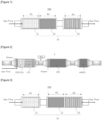
- FIG. 1 is a general schematic view showing a selective catalytic reduction system 100 for exhaust gas treatment according to the present embodiment.
- the selective catalytic reduction system 100 comprises one or more catalyst carriers 10 (catalyst carriers 11, 12 and 13), and a plurality of catalyst regions A provided on the catalyst carrier 10, and the catalyst region A comprises at least a catalyst region A1 as a first catalyst region containing iron-supported zeolite and arranged on the upstream side of an exhaust gas flow channel for exhaust gas flow (Gas Flow), a catalyst region A2 as a second catalyst region containing iron-supported zeolite and arranged on the downstream side of the exhaust gas flow channel with respect to the catalyst region A1, and a catalyst region A3 as a third catalyst region containing copper-supported zeolite and arranged on the downstream side of the exhaust gas flow channel with respect to the catalyst region A2.
- the iron-supported zeolite contains zeolite having one or more skeletal structures selected from the group consisting of BEA, CHA, FAU, MOR, MFI and FER, and iron supported on the zeolite, and the copper-supported zeolite contains zeolite having one or more skeletal structures selected from the group consisting of CHA, AEI, AFX and AFT, and copper supported on the zeolite.
- the selective catalytic reduction system 100 is arranged in an exhaust gas flow channel, and purifies an exhaust gas passing through the exhaust gas flow channel.
- the selective catalytic reduction system 100 according to the present embodiment is preferably used for applications in which an exhaust gas discharged from a lean combustion engine such as a diesel engine is purified.
- the selective catalytic reduction system 100 adsorbs ammonia stemming from a reducing agent supplied from a reducing agent supplying unit Red. described later (ammonia generated by thermal decomposition etc., of a urea component when the reducing agent is a urea component), and brings NO x and ammonia into contact with each other to perform purification by reduction.
- honeycomb structures commonly used in, for example, automobile exhaust gas applications are preferably used.
- honeycomb structures include ceramic monolith carriers such as cordierite, silicon carbide and silicon nitrite, metal honeycomb carriers made of stainless steel or the like, wire mesh carriers made of stainless steel or the like, and steel wool-shaped knitted wire carriers.
- the shape thereof is not particularly limited, and one having any shape such as, for example, a prismatic column shape, a cylindrical shape, a spherical shape, a honeycomb shape or a sheet shape can be selected.
- One of these honeycomb structures can be used, or two or more thereof can be appropriately combined and used.
- honeycomb structures for automobile exhaust gas applications flow-through type structures in which gas flow channels communicate with one another, and wall flow type structures in which some of the end surfaces of the gas flow channels are closed and a gas can be fed through the wall surfaces of the gas flow channels are widely known, and both of these structures are applicable. From the viewpoint of suppressing an excessive increase in pressure loss, flow-through type honeycomb structures are preferably used.
- the catalyst region A1 is provided on the catalyst carrier 11
- the catalyst region A2 is provided on the catalyst carrier 12
- the catalyst region A3 is provided on the catalyst carrier 13.
- the catalyst regions A1, A2 and A3 mean, respectively, regions where catalyst materials are provided on the respective catalyst carriers 11, 12 and 13 in an exhaust gas flow direction (a length direction of each of the catalyst carriers 11, 12 and 13).
- the catalyst region A provided on the catalyst carrier 10 can be perceived as a group of the three catalyst regions A1, A2 and A3.
- the total length of the catalyst region A can be perceived as a sum of the lengths of the catalyst carriers 11, 12 and 13 in the exhaust gas flow direction.
- the selective catalytic reduction system 100 of the present embodiment has a configuration in which the catalyst region A3 is arranged separately from the catalyst regions A1 and A2.
- the volume (size) of the catalyst carrier 10 (catalyst carriers 11, 12 and 13), the amount of catalyst material supported on each catalyst carrier, and the like are not particularly limited, and can be appropriately adjusted with consideration given to the type, the displacement, and the like of lean combustion engine to which the catalyst carrier is applied, and depending on the required catalyst amount, purification performance, and the like.
- diesel engines range from those for compact cars with a displacement of about 1 L to those for heavy machines (heavy duties) with a displacement of more than 50 L, and NO x and N 2 O in the exhaust gas discharged from those diesel engines considerably vary depending on the operation state of the diesel engine, the method for control of combustion, and the like.
- the selective catalytic reduction system 100 of the present embodiment which is used for removing NO x and N 2 O in the exhaust gas discharged from those lean combustion engines can be selected in accordance with a diversity of diesel engine displacements ranging from about 1 L to more than 50 L. For example, adjustment can be appropriately made by increasing or decreasing the diameter and the length of a catalyst carrier and the like used, the types and the combination ratios of catalyst materials used, the amount of the catalyst region A supported and the coating length of the catalyst region A (catalyst regions A1, A2 and A3).
- a catalyst material containing at least zeolite is used as a catalyst material for forming the catalyst region A (hereinafter, sometimes referred to as a "zeolite-based catalyst material").
- zeolite-based catalyst material various zeolites heretofore used for this type of exhaust gas purifying catalyst can be used without particular limitation.
- Specific examples of the zeolite include, but are not particularly limited to, zeolites of Y type, A type, L type, beta type, mordenite type, ZSM-5 type, ferrierite type, mordenite type, CHA type, AEI type, AFX type, KFI type and SFW type, and crystal metal aluminophosphates such as SAPO and ALPO.
- zeolites can be used, or two or more thereof can be used in any combination and ratio.
- zeolite a large number of zeolites of various grades are commercially available from domestic and foreign manufacturers, and depending on required performance, commercial products of various grades can be used.
- the zeolite can also be produced by methods known in the art.
- the skeletal structures of zeolites are stored in databases by International Zeolite Association, hereinafter sometimes abbreviated as "IZA", and structures specified in the IUPAC structure code (hereinafter, also referred to simply as the "structure code”) are used for reference.
- XRD powder X-ray diffraction
- zeolite having a low Si/Al ratio (SAR: silica alumina ratio) has a large number of acid points, but is degraded to a large extent in the context of durability in coexistence with water vapor, whereas zeolite having a high Si/Al ratio is excellent in heat resistance, but tends to have a small number of acid points.
- the Si/Al ratio of zeolite used is preferably 1 to 500, more preferably 1 to 100, still more preferably 1 to 50.
- the average particle diameter D 50 of the zeolite is not particularly limited, and can be appropriately set depending on desired performance. From the viewpoint of maintaining a large specific surface area and enhancing heat resistance to increase the number of its own catalytically active sites, the average particle diameter D 50 of the zeolite is preferably 0.5 ⁇ m to 100 ⁇ m, more preferably 0.5 ⁇ m to 50 ⁇ m, still more preferably 0.5 ⁇ m to 30 ⁇ m.
- the BET specific surface area of the zeolite is not particularly limited, and can be appropriately set depending on desired performance. From the viewpoint of maintaining a large specific surface area and enhancing catalytic activity, the BET specific surface area by a BET one-point method is preferably 10 m 2 /g to 1000 m 2 /g, more preferably 50 m 2 /g to 1000 m 2 /g, still more preferably 100 m 2 /g to 1000 m 2 /g.
- cations are present as counter ions in zeolite, and the cation is generally an ammonium ion or a proton.
- zeolite as transition metal element ion-exchange zeolite in which cation sites of the zeolite are ion-exchanged with any of these transition metal elements.
- the transition metal element may be dispersively held in the zeolite, and is preferably supported on the surface of the zeolite. Examples of the transition metal element include, but are not particularly limited to, nickel (Ni), cobalt (Co), copper (Cu), iron (Fe), manganese (Mn) and rhenium (Re).
- the ion-exchange rate of the zeolite is not particularly limited, and is preferably 1% to 100%, more preferably 10% to 95%, still more preferably 30% to 90%.
- An ion-exchange rate of 100% means that all of cationic species in the zeolite are ion-exchanged with transition metal element ions.
- the amount of the transition metal element added with respect to the zeolite is preferably 0.1 mass% to 10 mass%, more preferably 1 mass% to 10 mass%, still more preferably 2 mass% to 8 mass% in terms of oxide (CuO or Fe 2 O 3 ). All of the transition metal elements added as ion-exchange species may be ion-exchanged, or some of the transition metal elements may be present in the form of an oxide such as copper oxide or iron oxide.
- a configuration in which the catalyst region A containing a zeolite-based catalyst material as mentioned above is provided on the catalyst carrier 10 enables achievement of high exhaust gas purification performance while inhibiting an increase in pressure loss.
- the catalyst region A1 contains, as a catalyst material, at least iron-supported zeolite containing zeolite having one or more skeletal structures selected from the group consisting of BEA, CHA, FAU, MOR, MFI and FER, and iron supported on the zeolite.
- the catalyst region A1 contains iron-supported zeolite which emits little N 2 O, and this, along with the catalyst regions A2 and A3 which are arranged as predetermined as described above, enables achievement of further improved NO x and N 2 O removal performance.
- iron-supported BEA type zeolite is preferable from the viewpoint of NO x removal performance at low temperature.
- the amount of the catalyst region A1 supported is not particularly limited, and can be appropriately set depending on desired performance. From the viewpoint of the balance between catalyst performance and pressure loss, etc., the amount of the catalyst region A1 supported is preferably 10 g/L to 500 g/L or less, more preferably 20 g/L to 400 g/L, still more preferably 40 g/L to 300 g/L in terms of zeolite per L of the catalyst carrier 11.
- the amount of Fe added with respect to zeolite is preferably 0.1 mass% to 10 mass%, more preferably 1.0 mass% to 8.0 mass%, still more preferably 1.5 mass% to 7.0 mass% in terms of oxide (Fe 2 O 3 ). All of the transition metal elements added as ion-exchange species may be ion-exchanged, or some of the transition metal elements may be present in the form of an oxide such as iron oxide.
- the catalyst region A2 contains, as a catalyst material, at least iron-supported zeolite containing zeolite having one or more skeletal structures selected from the group consisting of BEA, CHA, FAU, MOR, MFI and FER, and iron supported on the zeolite.
- the catalyst region A2 contains iron-supported zeolite which emits little N 2 O, and this, along with the catalyst regions A1 and A3 which are arranged as predetermined as described above, enables achievement of further improved NO x and N 2 O removal performance.
- iron-supported CHA type zeolite is preferable from the viewpoint of suppressing deterioration of purification performance due to the influence of poisoning by HC species.
- the amount of the catalyst region A2 supported is not particularly limited, and can be appropriately set depending on desired performance. From the viewpoint of the balance between catalyst performance and pressure loss, and the like, the amount of the catalyst region A2 supported is preferably 10 g/L to 500 g/L or less, more preferably 20 g/L to 400 g/L, still more preferably 40 g/L to 300 g/L in terms of zeolite per L of the catalyst carrier 12.
- the amount of Fe added with respect to zeolite is preferably 0.1 mass% to 10 mass%, more preferably 1.0 mass% to 8.0 mass%, still more preferably 1.5 mass% to 7.0 mass% in terms of oxide (Fe 2 O 3 ). All of the transition metal elements added as ion-exchange species may be ion-exchanged, or some of the transition metal elements may be present in the form of an oxide such as iron oxide.
- the catalyst region A3 contains, as a catalyst material, at least copper-supported zeolite containing zeolite having one or more skeletal structures selected from the group consisting of CHA, AEI, AFX and AFT, and copper supported on the zeolite.
- the catalyst region A3 contains copper-supported zeolite which exhibits a high NO x removal rate over a wide range of NO 2 /NO x ratios, and this, along with the catalyst regions A1 and A2 which are arranged as predetermined as described above, enables achievement of further improved NO x and N 2 O removal performance.
- copper-supported CHA type zeolite is preferable from the viewpoint of reducing NO x emissions.
- the amount of the catalyst region A3 supported is not particularly limited, and can be appropriately set depending on desired performance. From the viewpoint of the balance between catalyst performance and pressure loss, and the like, the amount of the catalyst region A3 supported is preferably 10 g/L to 500 g/L or less, more preferably 20 g/L to 400 g/L, still more preferably 40 g/L to 300 g/L in terms of zeolite per L of the catalyst carrier 13.
- the amount of Cu added with respect to zeolite is preferably 0.1 mass% to 10 mass%, more preferably 1.0 mass% to 8.0 mass%, still more preferably 1.5 mass% to 7.0 mass% in terms of oxide (CuO). All of the transition metal elements added as ion-exchange species may be ion-exchanged, or some of the transition metal elements may be present in the form of an oxide such as copper oxide.
- the total amount of the catalyst region A supported is not particularly limited, and can be appropriately set depending on desired performance. From the viewpoint of NO x and N 2 O removal performance, the total amount of the catalyst region A supported is preferably 50 g/L or more and 800 g/L or less, more preferably 100 g/L or more and 700 g/L or less, still more preferably 150 g/L or more and 600 g/L or less.
- the lengths of the catalyst regions A1, A2 and A3 supported are not particularly limited, and can each be appropriately set depending on desired performance. From the viewpoint of NO x and N 2 O removal performance, it is preferable to satisfy the following relationship when the total length of the catalyst regions A1, A2 and A3 supported is defined as 100.
- the length of the catalyst region A1 supported is preferably 5 to 40, more preferably 8 to 30.
- the length of the catalyst region A2 supported is preferably 5 to 40, more preferably 8 to 30.
- the length of the catalyst region A3 supported is preferably 50 to 90, more preferably 40 to 84.
- the ranges where the catalyst regions A1, A2 and A3 are formed are not particularly limited.
- the catalyst regions A1, A2 and A3 may be formed over the entire length of the catalyst carriers 11, 12 and 13, respectively, or may be formed only on a part of the catalyst carriers 11, 12 and 13, respectively, in the exhaust gas flow direction.
- the catalyst regions A1, A2 and A3 may be formed on the upstream side or the downstream side of the catalyst carriers 11, 12 and 13 in the exhaust gas flow direction.
- the catalyst region A may contain oxygen storage and release materials having not only an excellent oxygen storage capacity but also relatively high heat resistance, such as seria-based oxides and ceria-zirconia-based composite oxides, and other base material particles which have been heretofore used for this type of exhaust gas purifying catalyst.
- Examples of other base material particles include inorganic compounds known in the art, for example, oxides such as aluminum oxides (alumina: Al 2 O 3 ) such as ⁇ -alumina, ⁇ -alumina, ⁇ -alumina, ⁇ -alumina and ⁇ -alumina, zirconium oxide (zirconia: ZrO 2 ), silicon oxide (silica: SiO 2 ) and titanium oxide (titania: TiO 2 ), and composite oxides containing any of these oxides as a main component, and the type thereof is not particularly limited. They may be composite oxides or solid solutions containing a rare earth element such as lanthanum or yttrium, a transition metal element or an alkaline earth metal. One type of these oxygen storage and release materials and other base material particles can be used, or two or more thereof can be used in any combination and ratio.
- oxides such as aluminum oxides (alumina: Al 2 O 3 ) such as ⁇ -alumina, ⁇ -alumina, ⁇ -alumina, ⁇ -alumina and
- the catalyst region A may contain various catalyst materials and co-catalyst known in the art, and various additives.
- the catalyst region A may contain binders such as a variety of sols such as, for example, boehmite, alumina sol, titania sol, silica sol and zirconia sol; and soluble salts such as aluminum nitrate, aluminum acetate, titanium nitrate, titanium acetate, zirconium nitrate and zirconium acetate.
- the catalyst region A (catalyst regions A1, A2 and A3) may further contain a Ba-containing compound in addition to the above-described components.
- the catalyst region A may contain a dispersion stabilizer such as a nonionic surfactant or an anionic surfactant; a pH adjuster; a viscosity modifier; and the like.
- a thickening agent is not particularly limited, and examples thereof include polysaccharides such as sucrose, polyethylene glycol, carboxymethyl cellulose and hydroxymethyl cellulose.
- the catalyst region A may contain an alkaline earth metal element such as Ca or Mg, and a platinum group element such as rhodium (Rh), ruthenium (Ru), palladium (Pd), platinum (Pt) or iridium (Ir) or a noble metal element such as gold (Au) or silver (Ag) as a catalytically active element.
- a platinum group element such as rhodium (Rh), ruthenium (Ru), palladium (Pd), platinum (Pt) or iridium (Ir) or a noble metal element such as gold (Au) or silver (Ag) as a catalytically active element.
- a platinum group element such as rhodium (Rh), ruthenium (Ru), palladium (Pd), platinum (Pt) or iridium (Ir) or a noble metal element such as gold (Au) or silver (Ag) as a catalytically active element.
- the platinum group elements and noble metal elements
- the content of the platinum group element and the noble metal element in the catalyst region A is preferably less than 3 g/L, more preferably less than 1 g/L, still more preferably less than 0.5 g/L in terms of the amount of metal per L of the catalyst carrier 10 (catalyst carriers 11, 12 and 13).
- the catalyst region A (catalyst regions A1, A2 and A3) may be directly placed on the catalyst carrier 10 (catalyst carriers 11, 12 and 13), or may be provided on the catalyst carrier 10 with a binder layer, an underlayer or the like interposed therebetween.
- a binder layer, an underlayer or the like one known in the art can be used, and the type thereof is not particularly limited.
- oxides such as oxygen storage and release materials (OSC) such as cerium oxide (ceria: CeO 2 ) and ceria-zirconia composite oxides (CZ composite oxides), aluminum oxides (alumina: Al 2 O 3 ) such as ⁇ -alumina, ⁇ -alumina, ⁇ -alumina, ⁇ -alumina and ⁇ -alumina, zirconium oxide (zirconia: ZrO 3 ), silicon oxide (silica: SiO 2 ) and titanium oxide (titania: TiO 2 ), and composite oxides containing any of these oxides as a main component.
- OSC oxygen storage and release materials
- CeO 2 cerium oxide
- CZ composite oxides ceria-zirconia composite oxides
- aluminum oxides alumina: Al 2 O 3
- zirconium oxide zirconia: ZrO 3
- silicon oxide siliconca: SiO 2
- titanium oxide titanium oxide
- the coating mass of the binder layer, the underlayer or the like is not particularly limited, and is preferably 1 g/L to 150 g/L, more preferably 10 g/L to 100 g/L per L of the catalyst carrier 10 (catalyst carriers 11, 12 and 13).
- the selective catalytic reduction system 100 of the present embodiment in which the catalyst region A1 that emits little N 2 O and has excellent NO x removal performance at low temperature is arranged on the upstream side, the catalyst region A2 that is excellent in resistance to deterioration of purification performance due to the influence of poisoning by HC species is arranged on the downstream side of the catalyst region A1, and the catalyst region A3 that exhibits a high NO x removal rate is arranged on the downstream side of the catalyst region A2, thus enables achievement of excellent NO x and N 2 O removal performance.
- FIG. 2 is a schematic view showing a general configuration of an exhaust gas purification apparatus 1 for lean combustion engines in which the selective catalytic reduction system 100 of the present embodiment is used as a SCR.
- the exhaust gas purification apparatus 1 for lean combustion engines comprises at least: at least one or more oxidation catalysts O x that are arranged in an exhaust gas flow channel and that oxidize at least one selected from the group consisting of CO, HC, NO and NH 3 in an exhaust gas discharged from a lean combustion engine such as diesel engine; a catalyst-coated particulate filter cPF that is arranged in the exhaust gas flow channel and that collects particulate components PM in the exhaust gas, and combusts or oxidizes and removes the particulate components; a reducing agent supplying unit Red.
- an ammonia oxidation catalyst that oxidizes and removes excess ammonia is further provided on the downstream side of the exhaust gas flow channel of the selective catalytic reduction system 100.
- a plasma generating apparatus PI. for plasma-treating an exhaust gas (not shown), and the like may be provided.
- the oxidation catalyst O x is a catalyst that oxidizes CO, HC, NO, NH 3 and the like in the exhaust gas.
- the oxidation catalyst O x conceptually includes, in addition to the above-described DOC, a lean NO x storage catalyst (LNT: lean NO x trap) which stores NO x under a lean condition and releases NO x under a rich condition to oxidize CO and HC to CO 2 and H 2 O and reduce NO x to N 2 , and catalyst-coated PF (cPF) obtained by applying such a catalyst onto PF.
- LNT lean NO x storage catalyst
- composite particles including base material particles of metal oxide such as alumina, zirconia and ceria and zeolite and platinum group elements (PGMs: platinum group metals) as catalytically active components supported on such carriers are generally used.
- PGMs platinum group elements
- catalysts are preferably used in which a catalyst layer including base material particles that are inorganic particulates and a platinum group element-supported catalyst material with a platinum group element supported on the base material particles is provided on an integral structure type catalyst carrier such as a honeycomb structure.
- an integral structure type catalyst carrier such as a honeycomb structure.
- an inorganic compound heretofore used in this type of exhaust gas purifying catalysts can be considered.
- oxides such as zeolite, cerium oxide (ceria: CeO 2 ), oxygen storage and release materials (OSC) such as ceria-zirconia composite oxides (CZ composite oxides), aluminum oxides (alumina: Al 2 O 3 ) such as ⁇ -alumina, ⁇ -alumina, ⁇ -alumina, ⁇ -alumina and ⁇ -alumina, zirconium oxide (zirconia: ZrO 2 ), silicon oxide (silica: SiO 2 ) and titanium oxide (titania: TiO 2 ), and composite oxides containing any of these oxides as a main component, and the type thereof is not particularly limited.
- the oxygen storage and release material means a material which stores or releases oxygen depending on an external environment.
- the average particle diameter D 50 of the base material particles of the oxidation catalyst O x can be appropriately set depending on desired performance, and is not particularly limited. From the viewpoint of maintaining a large specific surface area and enhancing heat resistance to increase the number of their own catalytically active sites, the average particle diameter D 50 of the base material particles is preferably 0.5 ⁇ m to 100 ⁇ m, more preferably 1 ⁇ m to 100 ⁇ m, still more preferably 1 ⁇ m to 50 ⁇ m.
- the BET specific surface area of the base material particles can be appropriately set depending on desired performance, and is not particularly limited, and from the viewpoint of maintaining a large specific surface area and enhancing catalytic activity, the BET specific surface area by the BET one-point method is preferably 10 m 2 /g to 500 m 2 /g, more preferably 20 m 2 /g to 300 m 2 /g, still more preferably 30 m 2 /g to 200 m 2 /g.
- various materials to be used as the base material particles of the oxidation catalyst O x a large number of materials of various grades are commercially available from domestic and foreign manufacturers, and depending on required performance, commercial products of various grades can be used as the base material particles.
- the base material particles can also be produced by methods known in the art.
- platinum group element examples include platinum (Pt), palladium (Pd), rhodium (Rh), ruthenium (Ru), iridium (Ir) and osmium (Os).
- platinum group elements include platinum (Pt), palladium (Pd), rhodium (Rh), ruthenium (Ru), iridium (Ir) and osmium (Os).
- One of the platinum group elements can be used, or two or more thereof can be used in any combination and ratio.
- the content ratio of the platinum group element in the oxidation catalyst O x is, normally, preferably 0.1 g/L to 20 g/L, more preferably 0.2 g/L to 15 g/L, still more preferably 0.3 g/L to 10 g/L.
- the oxidation catalyst O x may contain various other catalyst materials and co-catalyst known in the art and various additives.
- the oxidation catalyst O x may contain binders such as a variety of sols such as, for example, boehmite, alumina sol, titania sol, silica sol and zirconia sol; and soluble salts such as aluminum nitrate, aluminum acetate, titanium nitrate, titanium acetate, zirconium nitrate and zirconium acetate.
- the oxidation catalyst O x may further contain a Ba-containing compound in addition to the above-described components. By adding a Ba-containing compound, improvement of heat resistance, and activation of catalyst performance can be expected.
- the Ba-containing compound examples include, but are not particularly limited to, sulfates, carbonates, composite oxides and oxides. More specific examples thereof include BaO, Ba(CH 3 COO) 2 , BaO 2 , BaSO 4 , BaCO 3 , BaZrOs and BaAl 2 O 4 .
- the oxidation catalyst O x may contain a dispersion stabilizer such as a nonionic surfactant or an anionic surfactant; a pH adjuster; a viscosity modifier; and the like.
- honeycomb structures commonly used for automobile exhaust gas applications are preferably used.
- honeycomb structures include ceramic monolith carriers such as cordierite, silicon carbide and silicon nitrite, metal honeycomb carriers made of stainless steel or the like, wire mesh carriers made of stainless steel or the like, and steel wool-shaped knitted wire carriers.
- the shape thereof is not particularly limited, and one having any shape such as, for example, a prismatic column shape, a cylindrical shape, a spherical shape, a honeycomb shape or a sheet shape can be selected.
- One of these honeycomb structures can be used, or two or more thereof can be appropriately combined and used.
- honeycomb structures for automobile exhaust gas applications flow-through type structures in which gas flow channels communicate with one another, and wall flow type structures in which some of the end surfaces of the gas flow channels are closed and a gas can be fed through the wall surfaces of the gas flow channels are widely known, and both of these structures are applicable.
- the total coverage of the above-described catalyst layer is not particularly limited, and from the viewpoint of the balance between catalyst performance and pressure loss, etc., the total coverage per L of the integral structure type catalyst carrier is preferably 1 g/L to 500 g/L, more preferably 2 g/L to 450 g/L, still more preferably 2 g/L to 80 g/L for the wall flow type catalyst carrier and 50 g/L to 300 g/L for the flow-through type catalyst carrier.
- the oxidation catalyst O x may be directly placed on the integral structure type catalyst carrier, or may be provided on the integral structure type catalyst carrier with a binder layer, an underlayer or the like interposed therebetween.
- a binder layer, an underlayer or the like one known in the art can be used, and the type thereof is not particularly limited.
- oxides such as zeolite, cerium oxide (ceria: CeO 2 ), oxygen storage and release materials (OSC) such as ceria-zirconia composite oxides (CZ composite oxides), aluminum oxides (alumina: Al 2 O 3 ) such as ⁇ -alumina, ⁇ -alumina, ⁇ -alumina, ⁇ -alumina and ⁇ -alumina, zirconium oxide (zirconia: ZrO 2 ), silicon oxide (silica: SiO 2 ) and titanium oxide (titania: TiO 2 ), and composite oxides containing any of these oxides as a main component.
- the coating mass of the binder layer, the underlayer or the like is not particularly limited, and is preferably 1 g per L to 150 g per L, more preferably 10 g per L to 100 g per L of the integral structure type catalyst carrier.
- the number of the oxidation catalyst O x provided in the system of the exhaust gas flow channel of the exhaust gas purification apparatus 1 for lean combustion engines may be at least one, or may be two or more (e.g. two to five) depending on required performance etc.
- the oxidation catalysts O x may be the same type of oxidation catalysts, or different types of oxidation catalysts. It is also possible to use a zone-coated oxidation catalyst zO x obtained by zone-coating one catalyst carrier with two oxidation catalyst materials.
- the zone-coating is not particularly limited as long as a surface of one catalyst carrier is segmented and covered with a plurality of catalyst layers, and it is known that catalyst layers are applied differently in a concentric fashion to a center part and an outer peripheral part with respect to a through-hole direction (axis line) of a catalyst carrier (honeycomb structure), or applied differently in a through-hole depth direction of a honeycomb structure.
- axis line axis line
- honeycomb structure honeycomb structure
- the way in which the catalyst layers are applied differently in the zone-coating varies depending on the composition of harmful components to be removed, the flow rate, the temperature and the like, and an optimum combination is appropriately set.
- the oxidation catalysts O x may be arranged adjacently, or arranged separately in the exhaust gas flow channel with the selective catalytic reduction system 100, the catalyst-coated particulate filter cPF, the reducing agent supplying unit Red., the heating device (heater), the plasma generating apparatus PI. and the like interposed between the oxidation catalysts O x .
- the oxidation catalyst O x can be arranged on the upstream side of the exhaust gas flow channel with respect to the selective catalytic reduction system 100, or the oxidation catalyst O x can be arranged on the downstream side of the exhaust gas flow channel with respect to the selective catalytic reduction system 100, and when a plurality of oxidation catalysts O x are provided, these arrangement examples can be combined and applied.
- a particulate filter cPF obtained by applying a catalyst material to a particulate filter PF formed of the above-described wall flow type structure is provided on the downstream side of the above-described oxidation catalyst O x .
- the particulate filter PF (catalyst-coated particulate filter cPF) is aimed at trapping particulate components (PM) such as soot in the exhaust gas discharged from the lean combustion engine, and if necessary, spraying unburned light oil on a regular basis to combust or oxidize and remove the particulate components.
- Such particulate filters PF are widely known in the art as diesel particulate collection filters DPF, catalyst-coated diesel particulate collection filters cDPF, catalyzed combustion filters (CSF: catalyzed soot filter) and the like.
- the reducing agent supplying unit Red supplies one or more reducing agents selected from a urea component and an ammonia component into the exhaust gas flow channel.
- the reducing agent supplying unit Red. one known in the art can be used, and the type thereof is not particularly limited. Normally, one composed of a reducing agent storage tank, a pipe connected to the tank, and a spray nozzle mounted at the tip of the pipe is used (not shown).
- the spray nozzle of the reducing agent supplying unit Red. is placed on the upstream side of the selective catalytic reduction system 100.
- the above-described catalyst region A (catalyst regions A1, A2 and A3) excellent in NO x and N 2 O removal performance is employed, and therefore it is preferable that the spray nozzle of the reducing agent supplying unit Red. be placed immediately before the upstream side of the selective catalytic reduction system 100 for sufficiently exhibiting the function of the catalyst region A by eliminating other factors.
- spray nozzles of the reducing agent supplying unit Red. may be provided at a plurality of points in the case where these catalysts are arranged separately.
- the reducing component is selected from a urea component and an ammonia component.
- a urea component a standardized aqueous urea solution at a concentration of 31.8 mass% to 33.3 mass%, such as, for example, Adblue (product name) can be used.
- Adblue product name
- ammonia component aqueous ammonia as well as ammonia gas or the like can be used.
- a method is preferable in which rather than directly using NH 3 as a reducing component, aqueous urea is added from the upstream side of the selective catalytic reduction system 100 to generate NH 3 through thermal decomposition or hydrolysis, and the NH 3 is applied as the reducing agent.
- an electric heating device (heater) (catalyst heating device) is provided in the exhaust gas flow channel on the upstream side of the oxidation catalyst O x and the exhaust gas flow channel on the downstream side of the spray nozzle of the reducing agent supplying unit Red. and on the upstream side of the selective catalytic reduction system 100.
- the heating device is electrically connected to ECU and an on-vehicle power supply (not shown), and by controlling the power outputs of the ECU and the power supply, the temperature of the heating device (Heater), and hence the temperature of the exhaust gas in the exhaust gas flow channel can be controlled.
- the catalytic performance of the oxidation catalyst O x can be improved by, for example, applying heat with the heating device (heater) on the upstream side of the oxidation catalyst O x at the time of cold starting.
- One or more reducing agents selected from the group consisting of a urea component and an ammonia component and supplied from the reducing agent supplying unit Red. are heated with the heating device (Heater) in the exhaust gas flow channel to turn into NH 3 through thermal decomposition or hydrolysis, and adsorbed to the selective catalytic reduction system 100 on the downstream side of the exhaust gas flow channel.
- the reactivity of urea in the hydrolysis reaction can vary depending on the concentration, the combination composition, the pH and the like of aqueous urea, and can be efficiently controlled by controlling the temperature of the exhaust gas in the exhaust gas flow channel using the heating device (heater).
- the heating device herein, temperature sensors, NO x sensors and the like electrically connected to ECU are provided at various points, so that the NO x concentration and the exhaust gas temperature are monitored as needed.
- the heating device is composed of a metal honeycomb, a jacket type electric heating device mounted on the outer peripheral of the metal honeycomb, and a coil type electric heating device mounted so as to be partially embedded in the metal honeycomb main body (not shown).
- This metal honeycomb can be electrically heated by control of the control unit ECU, and by heat generation from the metal honeycomb, the temperature of the exhaust gas passing through the exhaust gas flow channel can be controlled.
- a heat insulating material is provided on the outer periphery of an exhaust gas flow channel over the entire length (not shown).
- the heat insulating material is not particularly limited, and can be appropriately selected from those known in the art, and for example, one obtained using cellulose fibers, rock wool or the like is suitably used.
- the heating device (Heater) used here may be, for example, a jacket type electric heating device or an electrically heated catalyst (EHC) with a SCR catalyst supported on the metal honeycomb main body. Heating of the metal honeycomb can also be performed by causing the metal honeycomb itself to generate heat directly with an electric current passing through the metal honeycomb main body. In this case, by connecting the metal honeycomb to an on-vehicle power supply and controlling the power output of the power supply by the control unit ECU, the temperature of the metal honeycomb, and hence the temperature of the exhaust gas in the exhaust flow channel can be controlled.
- EHC electrically heated catalyst
- an ammonia oxidation catalyst AMOX which oxidizes and removes excess ammonia is provided on the downstream side of the selective catalytic reduction system 100.
- the ammonia oxidation catalyst AMOX one known in the art can be used, and the type thereof is not particularly limited.
- the ammonia oxidation catalyst AMOX is additionally used if NO x or NH 3 cannot be purified to a regulatory value or a smaller value. Therefore, the ammonia oxidation catalyst AMOX includes a catalyst having a function of oxidizing NH 3 , and a catalyst component having a function of purifying NO x .
- the catalyst having a function of oxidizing NH 3 is preferably one in which one or more elements selected from platinum, palladium, rhodium and the like are supported on an inorganic material composed of one or more selected from alumina, silica, titania, zirconia and the like.
- an inorganic material whose heat resistance is improved by adding a co-catalyst such as a rare earth, an alkali metal or an alkaline earth metal.
- a co-catalyst such as a rare earth, an alkali metal or an alkaline earth metal.
- Platinum and palladium as noble metals exhibit excellent oxidative activity.
- the noble metal is supported on the inorganic material having a high specific surface area and high heat resistance, the noble metal component is hardly sintered, and thus the specific surface area of the noble metal is kept high to increase the number of active sites, so that high activity can be exhibited.
- the catalyst having a function of purifying NO x all of the non-zeolite-based catalyst materials and the zeolite-based catalyst materials described above can be used.
- the two types of catalysts may be uniformly mixed and applied to a honeycomb structure of integral type, but may be applied such that a catalyst having a function of oxidizing NH 3 forms a lower layer and a catalyst having a function of purifying NO x forms an upper layer.
- the volumes (sizes) of the ammonia oxidation catalyst AMOX, the coating mass of catalyst material, and the like are not particularly limited, and can be adjusted with consideration given to the type, the displacement and the like of an engine to which the exhaust gas purification apparatus 100 for lean combustion engines according to the present embodiment is applied, and depending on the required catalyst amount, purification performance and the like.
- ammonia oxidation catalysts AMOX described above may be provided depending on required performance or the like.
- the ammonia oxidation catalyst AMOX can also be used as zone-coated AMOX (zAMOX) by zone-coating one catalyst carrier with two catalyst materials.
- zAMOX zone-coated AMOX
- the arrangement state of the ammonia oxidation catalysts AMOX is not particularly limited. That is, a plurality of ammonia oxidation catalysts AMOX may be arranged adjacently or arranged separately.
- At least one of a plurality of ammonia oxidation catalysts AMOX be provided on the downstream side of the selective catalytic reduction system 100, and more preferably provided at the most downstream in the exhaust gas flow channel preferably containing the oxidation catalyst Ox and the selective catalytic reduction system 100.
- a plasma generating apparatus PI. for plasma-treating an exhaust gas is provided on the downstream side of the oxidation catalyst O x and on the upstream side on the selective catalytic reduction system 100.
- This plasma generating apparatus PI. is a so-called atmospheric pressure plasma generating apparatus (plasma reactor) which generates a low-temperature plasma obtained by discharge in the atmosphere or the like and having low electronic energy.
- the plasma generating apparatus PI. one known in the art can be used, and the type thereof is not particularly limited.
- the exhaust gas passing through the exhaust gas flow channel is treated with a plasma generated by the plasma generating apparatus PI., so that the NO x concentration can be further reduced (so-called plasma assisted SCR).
- the exhaust gas purification apparatus 1 for lean combustion engines can be used as an apparatus for purifying an exhaust gas generated from an internal-combustion engine such as diesel engine equipped with a urea SCR system, and is useful as an exhaust gas purifying catalyst for internal-combustion engines such as diesel engines, particularly an exhaust gas purification apparatus for diesel automobiles.
- the exhaust gas purification apparatus 1 for lean combustion engines can be arranged in the exhaust systems of various lean combustion engines.
- the numbers and locations of the oxidation catalyst O x , the reducing agent supplying unit Red., the catalyst-coated particulate filter cPF, the selective catalytic reduction system 100, the plasma generating apparatus PI., the reducing agent supplying unit Red., the ammonia oxidation catalyst AMOX and the like placed, and the arrangements thereof are not particularly limited to those in the present embodiment, can be appropriately adjusted according to the exhaust gas regulation, the type and the displacement of lean combustion engines applied, the required catalyst amount and purification performance, and the like, and are not particularly limited.
- the placement location can be appropriately selected from a plurality of locations such as positions immediately below the exhaust system and positions below the floor behind the exhaust system. It is also possible to further provide selective reduction catalysts SCR other than the selective catalytic reduction system 100.
- FIG. 3 is a general schematic view showing a selective catalytic reduction system 200 for exhaust gas treatment according to the present embodiment.
- the selective catalytic reduction system 200 of the present embodiment has the same configuration as in the first embodiment except that the catalyst region A1 is arranged separately from the catalyst regions A2 and A3. Such a configuration also enables the implementation of the selective catalytic reduction system for exhaust gas treatment according to the present disclosure.
- FIG. 4 is a general schematic view showing a selective catalytic reduction system 300 for exhaust gas treatment according to the present embodiment.
- the selective catalytic reduction system 300 of the present embodiment has the same configuration as in the first embodiment except that the catalyst region A1, the catalyst region A2 and the catalyst region A3 are arranged separately. Such a configuration also enables the implementation of the selective catalytic reduction system for exhaust gas treatment according to the present disclosure.
- FIG. 5 is a general schematic view showing a selective catalytic reduction system 400 for exhaust gas treatment according to the present embodiment.
- the selective catalytic reduction system 400 of the present embodiment has the same configuration as in the first embodiment except that the catalyst region A1, the catalyst region A2 and the catalyst region A3 are arranged adjacently. Such a configuration also enables the implementation of the selective catalytic reduction system for exhaust gas treatment according to the present disclosure.
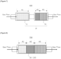
- FIG. 6 is a general schematic view showing a selective catalytic reduction system 500 for exhaust gas treatment according to the present embodiment.
- the selective catalytic reduction system 500 of the present embodiment has the same configuration as in the first embodiment except that the catalyst region A1 and the catalyst region A2 are provided on one catalyst carrier 14 by zone-coating on the catalyst carrier 14. Such a configuration also enables the implementation of the selective catalytic reduction system for exhaust gas treatment according to the present disclosure.
- FIG. 7 is a general schematic view showing a selective catalytic reduction system 600 for exhaust gas treatment according to the present embodiment.
- the selective catalytic reduction system 600 of the present embodiment has the same configuration as in the first embodiment except that the catalyst region A2 and the catalyst region A3 are provided on one catalyst carrier 15 by zone-coating on the catalyst carrier 15. Such a configuration also enables the implementation of the selective catalytic reduction system for exhaust gas treatment according to the present disclosure.
- FIG 8 is a general schematic view showing a selective catalytic reduction system 700 for exhaust gas treatment according to the present embodiment.
- the selective catalytic reduction system 700 of the present embodiment has the same configuration as in the first embodiment except that the catalyst region A1, the catalyst region A2 and the catalyst region A3 are provided on one catalyst carrier 16 by zone-coating on the catalyst carrier 16. Such a configuration also enables the implementation of the selective catalytic reduction system for exhaust gas treatment according to the present disclosure.
- Fe-supported BEA type zeolite was obtained by supporting Fe on BEA type zeolite prepared by hydrothermal synthesis method (SAR: 10, containing Fe at 4.8 mass% in terms of Fe 2 O 3 ).
- a binder, a surfactant and deionized water were mixed in predetermined amounts with the Fe-supported BEA type zeolite, and the mixture was milled with a ball mill to obtain a catalyst slurry 1.
- Fe-supported CHA type zeolite was obtained by supporting Fe on CHA type zeolite prepared by hydrothermal synthesis method (SAR: 24, containing Fe at 2.9 mass% in terms of Fe 2 O 3 ).
- a binder, zirconium acetate, a surfactant and deionized water were mixed in predetermined amounts with the Fe-supported CHA type zeolite, and the mixture was milled with a ball mill to obtain a catalyst slurry 2.
- Cu-supported CHA type zeolite was obtained by supporting Cu on CHA type zeolite prepared by hydrothermal synthesis method (SAR: 24, containing Cu at 3.8 mass% in terms of CuO).
- a binder, zirconium acetate, a surfactant and deionized water were mixed in predetermined amounts with the Cu-supported CHA type zeolite, and the mixture was milled with a ball mill to obtain a catalyst slurry 3.
- the catalyst slurry 1 was applied by a wash coating method to a honeycomb flow-through type cordierite catalyst carrier 1 being an integral structure type catalyst carrier (300 cpsi/5 mil, 10.5 ⁇ in diameter ⁇ 3 inch in length, 4.257 L), dried, and then fired in an air atmosphere at 550°C for 30 minutes to form a catalyst region on the catalyst carrier.
- the amount of the catalyst region supported per L of the catalyst carrier was set to 157 g/L.
- the catalyst slurry 2 was applied by a wash coating method to a honeycomb flow-through type cordierite catalyst carrier 2 being an integral structure type catalyst carrier (300 cpsi/5 mil, 10.5 ⁇ in diameter ⁇ 3 inch in length, 4.257 L), dried, and then fired in an air atmosphere at 550°C for 30 minutes to form a catalyst region on the catalyst carrier.
- the amount of the catalyst region supported per L of the catalyst carrier was set to 157 g/L.
- the catalyst slurry 3 was applied by a wash coating method to a honeycomb flow-through type cordierite catalyst carrier 3 being an integral structure type catalyst carrier (300 cpsi/5 mil, 10.5 ⁇ in diameter ⁇ 6 inch in length, 8.514 L), dried, and then fired in an air atmosphere at 550°C for 30 minutes to form a catalyst region on the catalyst carrier.
- the amount of the catalyst region supported per L of the catalyst carrier was set to 180 g/L.
- the catalyst slurry 3 was applied by a wash coating method to a honeycomb flow-through type cordierite catalyst carrier 4 being an integral structure type catalyst carrier (300 cpsi/5 mil, 10.5 ⁇ in diameter ⁇ 3 inch in length, 4.257 L), dried, and then fired in an air atmosphere at 550°C for 30 minutes to form a catalyst region on the catalyst carrier.
- the amount of the catalyst region supported per L of the catalyst carrier was set to 180 g/L.
- the catalyst-coated catalyst carriers of Production Examples 1 to 4 after the hydrothermal exposure were placed in a converter in a predetermined arrangement to conduct an engine test.
- an 8 L CRS TI tabletop diesel engine (with an 8 L common rail system with turbo intercooler) was used, and a DOC and a CSF were placed in this order on a side downstream by 1.0 m from the turbo exit of the engine.
- the catalyst-coated catalyst carriers of Production Examples 1 to 4 were placed in a converter in the arrangement shown in Table 1, followed by evaluation of exhaust gas purification performance.
- the concentrations of gases such as NO, NO 2 and N 2 O at the catalyst entrance and exit, and catalyst performance was evaluated.
- JIS No. 2 light oil (S content: 10 ppm or less on a mass basis) was used as a fuel.
- a DOC after durability treatment which was obtained by applying a composite supported catalyst with Pt and Pd supported on an alumina carrier to a honeycomb flow-through type cordierite catalyst carrier 1 (300 cpsi/5 mil, 10.5 ⁇ in diameter ⁇ 4.2 inch in length, 5.960 L) by a wash coating method, drying the catalyst, and then firing the catalyst in an air atmosphere at 550°C for 30 minutes, and then performing thermal durability treatment in the electric furnace at 600°C for 100 hours, was used (coating mass per L of catalyst carrier: 100 g/L, Pt coating mass in terms of metal: 1.3 g/L, Pd coating mass in terms of metal: 0.5 g/L).
- a CSF after durability treatment which was obtained by applying a composite supported catalyst with Pt and Pd supported on an alumina carrier to a honeycomb wall flow type cordierite catalyst carrier (260 cpsi/12 mil, 10.5 ⁇ in diameter ⁇ 7.3 inch in length, 10.358 L) by a wash coating method, drying the catalyst, and then firing the catalyst in an air atmosphere at 550°C for 30 minutes, and then performing thermal durability treatment in the electric furnace at 650°C for 100 hours, was used (coating mass per L of catalyst carrier: 20 g/L, Pt coating mass in terms of metal: 0.1 g/L, Pd coating mass in terms of metal: 0.05 g/L).
- the emissions of NO x and N 2 O components were evaluated by the FTP mode (federal test procedure).
- FTP is one of test modes in exhaust gas regulations set by United States Environmental Protection Agency.
- the SCR sample entrance temperature range in the FTP mode in the present evaluation is about 25°C to 305°C (cold) and about 145°C to 315°C (hot).
- the emissions of NO x and N 2 O components were measured under the condition of a SCR sample entrance average temperature of about 210°C. The measurement results are shown in Figure 9 .
- the exhaust gas purification apparatus for lean combustion engines and the selective reduction catalyst system according to the present disclosure involves relatively low cost per unit catalyst coating mass, and can exhibit excellent NO x removal performance under a condition of a relatively low to relatively high amount of ammonia adsorbed. Therefore, the exhaust gas purification apparatus for lean combustion engines and the selective reduction catalyst system according to the present disclosure can be widely and effectively utilized as exhaust gas purification apparatuses for lean combustion internal engines, and are particularly useful as exhaust gas purification apparatuses for lean burn gasoline cars and diesel cars.
Landscapes
- Chemical & Material Sciences (AREA)
- Engineering & Computer Science (AREA)
- Chemical Kinetics & Catalysis (AREA)
- Materials Engineering (AREA)
- Organic Chemistry (AREA)
- Combustion & Propulsion (AREA)
- Health & Medical Sciences (AREA)
- General Engineering & Computer Science (AREA)
- Mechanical Engineering (AREA)
- Toxicology (AREA)
- Oil, Petroleum & Natural Gas (AREA)
- Biomedical Technology (AREA)
- Environmental & Geological Engineering (AREA)
- Analytical Chemistry (AREA)
- General Chemical & Material Sciences (AREA)
- Crystallography & Structural Chemistry (AREA)
- Physics & Mathematics (AREA)
- Thermal Sciences (AREA)
- Catalysts (AREA)
- Exhaust Gas After Treatment (AREA)
Applications Claiming Priority (2)
| Application Number | Priority Date | Filing Date | Title |
|---|---|---|---|
| JP2022124488 | 2022-08-04 | ||
| PCT/JP2023/025624 WO2024029289A1 (fr) | 2022-08-04 | 2023-07-11 | Système de réduction catalytique sélective pour traitement de gaz d'échappement, et dispositif de purification de gaz d'échappement pour moteur à mélange pauvre utilisant celui-ci |
Publications (1)
| Publication Number | Publication Date |
|---|---|
| EP4566710A1 true EP4566710A1 (fr) | 2025-06-11 |
Family
ID=89849219
Family Applications (1)
| Application Number | Title | Priority Date | Filing Date |
|---|---|---|---|
| EP23849848.9A Pending EP4566710A1 (fr) | 2022-08-04 | 2023-07-11 | Système de réduction catalytique sélective pour traitement de gaz d'échappement, et dispositif de purification de gaz d'échappement pour moteur à mélange pauvre utilisant celui-ci |
Country Status (4)
| Country | Link |
|---|---|
| US (1) | US20260021449A1 (fr) |
| EP (1) | EP4566710A1 (fr) |
| JP (1) | JPWO2024029289A1 (fr) |
| WO (1) | WO2024029289A1 (fr) |
Families Citing this family (1)
| Publication number | Priority date | Publication date | Assignee | Title |
|---|---|---|---|---|
| JP2025132849A (ja) * | 2024-02-29 | 2025-09-10 | 三菱重工業株式会社 | アンモニア分解触媒および排ガス処理方法 |
Family Cites Families (5)
| Publication number | Priority date | Publication date | Assignee | Title |
|---|---|---|---|---|
| KR20170038927A (ko) * | 2014-08-07 | 2017-04-07 | 존슨 맛쎄이 퍼블릭 리미티드 컴파니 | 배기가스를 처리하기 위한 구역화된 촉매 |
| KR20250174716A (ko) * | 2015-02-27 | 2025-12-12 | 바스프 코포레이션 | 배기 가스 처리 시스템 |
| JP6895894B2 (ja) * | 2015-03-30 | 2021-06-30 | ビーエーエスエフ コーポレーション | ディーゼル排出物制御のための多機能フィルタ |
| WO2020116020A1 (fr) * | 2018-12-06 | 2020-06-11 | エヌ・イーケムキャット株式会社 | Dispositif de purge de gaz d'échappement |
| JP7566569B2 (ja) * | 2020-10-14 | 2024-10-15 | エヌ・イーケムキャット株式会社 | 排ガス浄化用触媒システム |
-
2023
- 2023-07-11 EP EP23849848.9A patent/EP4566710A1/fr active Pending
- 2023-07-11 US US19/099,964 patent/US20260021449A1/en active Pending
- 2023-07-11 JP JP2024538891A patent/JPWO2024029289A1/ja active Pending
- 2023-07-11 WO PCT/JP2023/025624 patent/WO2024029289A1/fr not_active Ceased
Also Published As
| Publication number | Publication date |
|---|---|
| JPWO2024029289A1 (fr) | 2024-02-08 |
| US20260021449A1 (en) | 2026-01-22 |
| WO2024029289A1 (fr) | 2024-02-08 |
Similar Documents
| Publication | Publication Date | Title |
|---|---|---|
| CN103442805B (zh) | 氨氧化催化剂以及使用了其的废气净化装置和废气净化方法 | |
| JP6007306B2 (ja) | アンモニア酸化触媒、および排気ガス浄化装置並びに排気ガス浄化方法 | |
| JP5769708B2 (ja) | 選択還元型触媒を用いた排気ガス浄化装置及び排気ガス浄化方法 | |
| EP2922631B1 (fr) | Filtre à suie supportant un catalyseur pour le traitement de gaz d'échappement d'un moteur à alumage par compression | |
| JP5110954B2 (ja) | 選択還元型触媒を用いた排気ガス浄化触媒装置並びに排気ガス浄化方法 | |
| JP6040232B2 (ja) | 排気ガス浄化装置 | |
| JP5769732B2 (ja) | 選択還元型触媒、およびそれを用いた排気ガス浄化装置並びに排気ガス浄化方法 | |
| EP2113296A2 (fr) | Procédé de purification de gaz d'échappement utilisant un catalyseur de réduction sélectif | |
| EP1985353A1 (fr) | Catalyseur de purification de gaz d'échappement pour automobile, système catalytique pour la purification de gaz d'échappement et processus de purification de gaz d'échappement | |
| EP3892837B1 (fr) | Dispositif de purge de gaz d'échappement | |
| EP4039356B1 (fr) | Dispositif de purification de gaz d'échappement | |
| JP2013139035A (ja) | 選択還元触媒を用いた排気ガス浄化方法 | |
| EP4566710A1 (fr) | Système de réduction catalytique sélective pour traitement de gaz d'échappement, et dispositif de purification de gaz d'échappement pour moteur à mélange pauvre utilisant celui-ci | |
| JP7634475B2 (ja) | ディーゼル用選択的還元触媒及びディーゼル排ガス浄化装置 | |
| WO2024029290A1 (fr) | Système de traitement de gaz d'échappement |
Legal Events
| Date | Code | Title | Description |
|---|---|---|---|
| STAA | Information on the status of an ep patent application or granted ep patent |
Free format text: STATUS: THE INTERNATIONAL PUBLICATION HAS BEEN MADE |
|
| PUAI | Public reference made under article 153(3) epc to a published international application that has entered the european phase |
Free format text: ORIGINAL CODE: 0009012 |
|
| STAA | Information on the status of an ep patent application or granted ep patent |
Free format text: STATUS: REQUEST FOR EXAMINATION WAS MADE |
|
| 17P | Request for examination filed |
Effective date: 20250207 |
|
| AK | Designated contracting states |
Kind code of ref document: A1 Designated state(s): AL AT BE BG CH CY CZ DE DK EE ES FI FR GB GR HR HU IE IS IT LI LT LU LV MC ME MK MT NL NO PL PT RO RS SE SI SK SM TR |
|
| DAV | Request for validation of the european patent (deleted) | ||
| DAX | Request for extension of the european patent (deleted) |