EP4566780A1 - Maschine zur bearbeitung einer platte und verfahren zur bearbeitung einer platte - Google Patents
Maschine zur bearbeitung einer platte und verfahren zur bearbeitung einer platte Download PDFInfo
- Publication number
- EP4566780A1 EP4566780A1 EP24217371.4A EP24217371A EP4566780A1 EP 4566780 A1 EP4566780 A1 EP 4566780A1 EP 24217371 A EP24217371 A EP 24217371A EP 4566780 A1 EP4566780 A1 EP 4566780A1
- Authority
- EP
- European Patent Office
- Prior art keywords
- panel
- working area
- zone
- machine
- auxiliary system
- Prior art date
- Legal status (The legal status is an assumption and is not a legal conclusion. Google has not performed a legal analysis and makes no representation as to the accuracy of the status listed.)
- Pending
Links
Images

Classifications
-
- B—PERFORMING OPERATIONS; TRANSPORTING
- B27—WORKING OR PRESERVING WOOD OR SIMILAR MATERIAL; NAILING OR STAPLING MACHINES IN GENERAL
- B27M—WORKING OF WOOD NOT PROVIDED FOR IN SUBCLASSES B27B - B27L; MANUFACTURE OF SPECIFIC WOODEN ARTICLES
- B27M1/00—Working of wood not provided for in subclasses B27B - B27L, e.g. by stretching
- B27M1/08—Working of wood not provided for in subclasses B27B - B27L, e.g. by stretching by multi-step processes
-
- B—PERFORMING OPERATIONS; TRANSPORTING
- B23—MACHINE TOOLS; METAL-WORKING NOT OTHERWISE PROVIDED FOR
- B23Q—DETAILS, COMPONENTS, OR ACCESSORIES FOR MACHINE TOOLS, e.g. ARRANGEMENTS FOR COPYING OR CONTROLLING; MACHINE TOOLS IN GENERAL CHARACTERISED BY THE CONSTRUCTION OF PARTICULAR DETAILS OR COMPONENTS; COMBINATIONS OR ASSOCIATIONS OF METAL-WORKING MACHINES, NOT DIRECTED TO A PARTICULAR RESULT
- B23Q1/00—Members which are comprised in the general build-up of a form of machine, particularly relatively large fixed members
- B23Q1/03—Stationary work or tool supports
- B23Q1/037—Stationary work or tool supports comprising series of support elements whose relative distance is adjustable
-
- B—PERFORMING OPERATIONS; TRANSPORTING
- B23—MACHINE TOOLS; METAL-WORKING NOT OTHERWISE PROVIDED FOR
- B23Q—DETAILS, COMPONENTS, OR ACCESSORIES FOR MACHINE TOOLS, e.g. ARRANGEMENTS FOR COPYING OR CONTROLLING; MACHINE TOOLS IN GENERAL CHARACTERISED BY THE CONSTRUCTION OF PARTICULAR DETAILS OR COMPONENTS; COMBINATIONS OR ASSOCIATIONS OF METAL-WORKING MACHINES, NOT DIRECTED TO A PARTICULAR RESULT
- B23Q3/00—Devices holding, supporting, or positioning work or tools, of a kind normally removable from the machine
- B23Q3/02—Devices holding, supporting, or positioning work or tools, of a kind normally removable from the machine for mounting on a work-table, tool-slide, or analogous part
- B23Q3/06—Work-clamping means
- B23Q3/08—Work-clamping means other than mechanically-actuated
- B23Q3/088—Work-clamping means other than mechanically-actuated using vacuum means
Definitions
- This invention relates to a machine for machining a panel and to a method for machining a panel.
- the invention relates to a machining centre, or MC for short, for machining panels made of wood or comparable materials, such as, for example, wood by-products, metal, plastic and composites.
- the invention relates to a machining centre for machining wooden panels and to a method for machining a panel, where the panel is loaded, or unloaded, manually by an operator.
- a MC for machining wooden panels may comprise a plurality of gripping elements, in particular, supporting suction cups, or suction cups for short, which are designed to support and hold the panel in place while it is being machined.
- the suction cups are typically used in the machining of panels, that is to say, of parts having two dimensions (length and width) which are predominant with respect to a third dimension (thickness), whilst parts made of solid wood, for example, wooden "squares", i.e. oblong elements with rectangular cross section, are typically supported and held in place by suitable grippers.
- the suction cups are distributed in a working area oriented according to a working plane.
- the working plane is typically parallel to the supporting surface of the MC and may extend along a longitudinal axis and a transverse axis perpendicular to the longitudinal axis.
- the MC may comprise, for example, a plurality of bars (forming what is known as a barred work table, or barred table for short), which may extend, for example, along the transverse axis, may be disposed, for example, alongside and parallel to each other, and may be movable along the longitudinal axis both manually and automatically.
- Each bar of the barred table may comprise a plurality of suction cups for supporting and holding the panel to be machined in place.
- the suction cups may be coupled to each bar, for example removably and/or movably, either manually or automatically, along the transverse axis.
- the working area has an operator side, oriented longitudinally and facing an operator zone.
- the operator zone is the zone from which the operator typically controls the MC, for example using a control desk located in the operator zone.
- the MC has only one operator side, which is the side that is directly accessible to the operator working in the operator zone, for example for panel loading and unloading operations.
- a MC may comprise a machining unit configured to support and move a machining tool on the working area.
- the machining unit may comprise a chuck, to which the machining tool may be coupled, for example removably.
- the machining tool, rotating on the chuck (for example, an electric chuck) can machine the panel by stock removal.
- the tool may be movable relative to the working area, for example along three Cartesian axes, in particular, the longitudinal axis, the transverse axis and a vertical axis orthogonal to the longitudinal and transverse axes.
- the tool may be movable relative to the working plane according to one or more rotary axes: for example, two rotary axes typically called B and C.
- MCs may be configured to be able to support a plurality of panels to be machined simultaneously in the working area, so as to be able to machine the plurality of panels in sequence and uninterruptedly.
- This technique increases the efficiency and productivity of the MC, reducing machine downtimes due to panel loading and unloading operations for each machining process.
- the working area may be considered as being subdivided virtually into a plurality of working zones where the panels can be loaded and unloaded. The working zones may therefore be proximal or distal to the operator side.
- MCs which are configured to support a plurality of panels simultaneously in the working area may be loaded and/or unloaded manually or automatically.
- panel loading and unloading operations may be carried out, for example, by devices outside the machining centre, such as robots, which are expensive, cumbersome and require additional safety systems.
- Figure 1 in patent document EP3804930A1 shows a machining centre for machining a wooden panel and comprising a robot for loading and unloading the panel into and from the different working zones which are identified, in the working area, by the reference letters A, B., C and D.
- storage areas must be provided at known positions so that the robot can go and pick up or unload the panels correctly.
- the robot works in the zone of the machine opposite the operator zone.
- having the automatic loading and unloading system with the robot in the zone opposite the operator zone increases the overall dimensions of the machine.
- this solution involves high costs and the need to provide the machine with additional safety systems to ensure the safety of the operator during the operation of the MC.
- automatic loading and unloading may be carried out by devices inside the machining centre such as, for example, pick-up and moving systems located in the working area.
- pick-up and moving systems located in the working area.
- Such pick-up and moving systems being fully automatic, involve high costs and make the MC complex, resulting in a high number of breakdowns and increased machine downtime.
- patent document EP2842706A1 describes a MC for machining square wooden elements and comprising a barred working plane fitted with grippers for supporting and holding in place the elements to be machined. Inside the working area there is also an additional gripping system, located between the bars of the barred plane, to load and unload the wooden elements automatically in the different working areas. The use of grippers to support and hold the elements in place in the working area makes the MC unsuitable for the machining of panels. Further, the loading and unloading system is configured for automatically loading and unloading square wooden elements and thus requires storage areas to be provided to store the square elements and a feeding system to move the square elements from the storage areas to the working plane.
- the feeding system is located in the zone of the machine opposite the operator zone, which means increasing the overall dimensions of the machine. Further, the feeding system and the additional gripping system, being fully automatic, involve high costs and make the MC more complex, with the risk of frequent failures and machine downtimes.
- a manually loaded MC is therefore more economical and compact than automatically loaded MCs.
- a manually loaded MC is simpler and less subject to breakdowns and downtime.
- operators have access to the working area of the MC only from the operator side.
- panel loading and unloading operations are easy when working in zones close to the operator side, but the same is not true when working in zones further away from the operator side. Indeed, in the latter case, the operator has to lean over the working area while supporting and transporting the panel to be machined or already machined, with a serious risk of accidents or of dropping and damaging the panel or the MC.
- the aim of this disclosure is to provide a machine for machining a panel and a method for machining a panel to overcome the above mentioned disadvantages of the prior art.
- the aim of this disclosure is to provide a machine for machining a panel and a method for machining a panel to make it easier and safer for the operator to carry out loading and/or unloading operations, especially in the working zones opposite the operator side.
- Another aim of this disclosure is to provide a machine for machining a panel and which is compact, economical and reliable.
- the means for loading the panel that is to say, the auxiliary system for the operations described herein to load the panel from the working zone proximal to the operator side to the working zone distal to the operator side may be used in the same way for the operations to unload the panels from the working zone distal to the operator side to the working zone proximal to the operator side. Therefore, even if the description refers mainly to the loading of panels in a machine for machining a panel, it is understood that the scope of protection of the invention described herein, defined by the accompanying claims, comprises the loading and/or unloading of the panels in a machine for machining a panel and in the respective method.
- This disclosure provides a machine for machining a panel, comprising a plurality of supporting suction cups, configured to support and lock a panel to be machined on a working area oriented according to a working plane extending along a longitudinal axis and a transverse axis perpendicular to the longitudinal axis.
- the working area has an operator side oriented longitudinally and facing an operator zone, so as to be directly accessible to an operator positioned in the operator zone.
- the plurality of supporting suction cups may be distributed, in the working area, along the transverse axis, between a zone proximal to the operator side (called proximal zone of the working area) and a zone distal to the operator side (called distal zone of the working area).
- the machine may also comprise a machining unit which is movable on the working area and configured to machine the panel. More specifically, the machine may also comprise a raiser which is movable between a lowered position, where it is disposed below the working plane, and a raised position, where it is configured to support the panel at a level above the working plane.
- the machine may also comprise an auxiliary system, having an active configuration, where it is operatively coupled to the panel, and an inactive configuration, where it is uncoupled from the panel.
- the auxiliary system may be movable along the transverse axis so as to move the panel from the proximal zone to the distal zone of the working area to make it easier for the operator to load the panel in the zone distal to the working area.
- the raiser may extend along the transverse axis, from the proximal zone to the distal zone of the working area, and may be disposed in the working area so it is spaced from the auxiliary system along the longitudinal axis. That way, the auxiliary system and the raiser can act in conjunction to support the panel when the auxiliary system is in the active configuration and the raiser is at the raised position. This allows panels of different shapes and sizes to be supported better in the working plane, particularly advantageously when the auxiliary system is moving the panels along the transverse axis.
- the raiser may comprise a first raiser, configured to support the panel in the proximal zone of the working area, and a second raiser, configured to support the panel in the distal zone of the working area, so as to make it easier to support and handle more than one panel in the working area of the machine, in particular one in the proximal zone and one in the distal zone of the working area.
- the first raiser and the second raiser may be movable between the raised position and the lowered position independently of each other.
- the machine may comprise a plurality of raisers, each of the plurality of raisers extending along the transverse axis, parallel to the other raisers of the plurality of raisers and disposed in the working area so as to be spaced from the other raisers of the plurality of raisers along the longitudinal axis, so that the machine, and in particular the working area, can be adapted to panels of different shapes and sizes.
- the auxiliary system may be coupled to the raiser.
- the auxiliary system may be coupled to the raiser so as to be movable along a vertical axis perpendicular to the working plane.
- the auxiliary system may thus move together with the raiser as the raiser moves from the lowered position, where it is disposed below the working plane, to the raised position, where it is configured to support the panel at a level above the working plane, and vice versa.
- the auxiliary system may move relative to the raiser along the vertical axis, for example into the active configuration, where it is operatively coupled to the panel, or into the inactive configuration, where it is uncoupled from the panel. This movement may be carried out via an actuator such as, for example, an electric motor or a piston.
- the machine may comprise a plurality of auxiliary systems, each coupled to a respective raiser of the plurality of raisers.
- the auxiliary system may be disposed along a transverse side of the working area parallel to the transverse axis. This gives the machine, and in particular the working area, a more simple mechanical structure. More advantageously, the machine may have two auxiliary systems, one at each transverse side of the working area.
- the auxiliary system may also comprise a gripper, or a locking suction cup, configured to grip the panel when the auxiliary system is in the active configuration, and to release the panel when the auxiliary system is in the inactive configuration.
- the auxiliary system comprises a transverse actuator configured to move the auxiliary system along the transverse axis, from the proximal zone of the working area to the distal zone of the working area.
- the transverse actuator may be an electric motor, synchronous or asynchronous, for example, or a pneumatic actuator such as a piston, for example.
- the machine may comprise a plurality of reference stops for referencing the panel relative to the working area, and the auxiliary system comprises a reference stop of the plurality of reference stops. More advantageously, the machine may comprise a plurality of bars, where each of the plurality of bars extends along the transverse axis and supports a plurality of supporting suction cups, and where the plurality of bars are disposed in the working area alongside and parallel to each other.
- This disclosure provides a method for machining a panel in a machine for machining wood, comprising, for example, a plurality of supporting suction cups, configured to support and lock a panel to be machined on a working area oriented according to a working plane extending along a longitudinal axis and a transverse axis perpendicular to the longitudinal axis, where the working area has an operator side oriented longitudinally and facing an operator zone, to be directly accessible to an operator positioned in the operator zone, the plurality of supporting suction cups being distributed, in the working area, along the transverse axis, between a zone proximal to the operator side and a zone distal to the operator side.
- the method may comprise the step of moving the raiser from the raised position to the lowered position.
- the method may comprise the step of locking the panel in the working plane by means of at least one suction cup of a plurality of supporting suction cups.
- the method may comprise the step of passing the auxiliary system from the active configuration to the inactive configuration.
- the raiser may extend along the transverse axis and may support the panel during the entire step of moving the auxiliary system along the transverse axis from the proximal zone to the distal zone of the working area.
- the raiser comprises a first raiser, configured to support the panel in the proximal zone of the working area, and a second raiser, configured to support the panel in the distal zone of the working area, and during the step of moving the raiser from the lowered position to the raised position, both the first raiser and the second raiser are moved, whilst during the step of moving the raiser from the raised position to the lowered position, only the second raiser is moved.
- the method may also comprise the step, carried out by the operator, of abutting the panel against a plurality of reference stops so as to reference it relative to the working area.
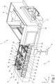
- Figure 1 shows a machine 1 for machining a panel, in particular, a machining centre, or MC for short.
- the machine 1 may comprise a bed 2 configured to substantially support all the fixed and movable parts of the machine 1.
- the machine 1 may comprise a plurality of supporting suction cups 33 configured to support and lock in place a panel P to be machined.
- the plurality of supporting suction cups 33 is particularly suitable for supporting and locking panels in place, in particular panels made of wood or comparable materials.
- Each suction cup of the plurality of suction cups 33 may, in effect, be in fluid-dynamic communication with a vacuum generating system (not shown in the drawings).
- the plurality of suction cups 33 may define a working area 3 oriented according to a working plane which may extend, for example, along a longitudinal axis X and a transverse axis Y perpendicular to the longitudinal axis X.
- the working plane may, for example, be substantially parallel to a supporting surface, such as a floor, which supports the machine 1.
- the plurality of suction cups 33 may be coupled to a bar 31, in particular to a plurality of bars 31.
- each of the plurality of bars 31 may extend along the transverse axis Y. Additionally, the bars of the plurality of bars 31 may be disposed alongside and spaced from each other along the longitudinal axis X.
- each of the plurality of bars 31 may be coupled to the bed 2 movably along the longitudinal axis X, and this movement may be carried out either manually, or automatically by means of actuators such as, for example, electric motors, in particular, synchronous motors.
- the supporting suction cups of the plurality of suction cups 33 may be coupled to each of the plurality of bars 31 removably and/or movably along the transverse axis Y. This movement may be carried out either manually, or automatically by means of actuators such as, for example, electric motors, in particular, synchronous motors.
- the suction cups of the plurality of suction cups 33 may therefore be disposed in the working area 3 in various different positions or configuration (for example in row or matrix form, etc) so that the machine 1 can support and lock in place one or more panels P of different shapes and sizes. In the case of two more panels P, two or more virtual working zones of the working area 3 may be defined.
- the working area 3 may have an operator side 30 which is parallel, for example, to the longitudinal axis X.
- the operator side 30 may face an operator zone O where, typically, there is an operator who controls the MC.
- the operator side 30 may be directly accessible to the operator working in the operator zone, for example for panel P loading and unloading operations.
- the operator may, for example, program, manage and control the machine 1.
- the machine 1 may also comprise a machining unit 4, configured to machine the panel P.
- the machining unit may be coupled to the bed 2 and movable in the working plane, for example along the longitudinal axis X.
- the machining unit 4 may comprise a machining head 41, housed in a protective enclosure 42.
- the machining head 41 may be movable relative to the working plane 3, for example along the transverse axis Y and the longitudinal axis X.
- the machining head 41 may be movable relative to the working plane 3, for example along a vertical axis Z, orthogonal to the longitudinal axis X and to the transverse axis Y.
- the machining head 41 may also have one or more rotation axes.
- the machining head 41 may comprises a chuck, such as, for example, an electric chuck, which is configured to support, for example removably, and drive in rotation a tool for machining the panel P.
- the machine 1 may also comprise an electric panel 5, configured to house electrical devices, for example for controlling and managing the machine 1.
- the machine 1 may comprise one or more raisers 32.
- the raisers 32 may extend along the transverse axis Y. Additionally, the raisers 32 may be disposed alongside each other, spaced apart and parallel to each other along the longitudinal axis X. Furthermore, the raisers 32 may be coupled to the bed 2 movably along the longitudinal axis X, and this movement may be carried out either manually, or automatically by means of actuators such as, for example, electric motors, in particular, synchronous motors. Furthermore, each raiser 32 may be coupled to the bed 2 by a respective bar of the plurality of bars 31.
- the raisers 32 may be movable independently, or synchronously, between a lowered position, where they are disposed below the working plane, and a raised position, where they are configured to support the panel P at a level above the working plane. This movement may be performed, for example, along the vertical axis Z.
- at the raised position at least one portion of the raisers 32 rises above the working plane so as to provide support for the panel P.
- a panel P, supported by one or more raisers 32 is at a level above the plurality of suction cups 33 and is therefore free to be positioned correctly in the working plane by sliding on the raisers 32.
- the raisers 32 may comprise a first raiser 32', configured to support the panel P in a zone of the working area proximal to the operator side 30 and called “proximal zone” for short. Furthermore, the raisers 32 may comprise a second raiser 32", configured to support the panel P in a zone of the working area distal to the operator side 30 and called “distal zone” for short.
- Each first raiser 32' of each raiser 32 may be coupled to a respective first actuator 321' to move each first raiser 32' from the lowered position to the raised position, and vice versa.
- Each first actuator 321' may be, for example, a pneumatic piston or an electric motor.
- each second raiser 32" of each raiser 32 may be coupled to a respective second actuator 321" to move each second raiser 32" from the lowered position to the raised position, and vice versa.
- Each second actuator 321" may be, for example, a pneumatic piston or an electric motor.
- the machine 1 may comprise a plurality of reference stops, 34, 72 for referencing the panel P relative to the working area 3.
- the machine may comprise a transverse reference stop 34, which allows referencing the panel P along the transverse axis Y, and a longitudinal reference stop 72, which allows referencing the panel P along the longitudinal axis X.
- each of the plurality of reference stops 34, 72 may be, for example, a cylindrical stem which is movable between a retracted position, where it is under the working plane, and an extended position, where it rises above the working plane.
- the operator may move the panel P until it abuts the plurality of reference stops 34, 72 so as to reference it relative to the working area 3.
- the movement described is carried out by making the panel P slide on one or more raisers 32.
- the machine 1 may comprise one or more auxiliary systems 7 for loading a panel P to be machined, in particular into the distal zone of the working area.
- the auxiliary system 7 may have an active configuration, in which it is operatively coupled to the panel P, and an inactive configuration, in which it is uncoupled from the panel P. Furthermore, the auxiliary system 7 may have a parked configuration.
- the parked configuration has the purpose of minimizing the space occupied by the auxiliary system 7 in the working area so as not to interfere with the machining processes to be carried out on the panel P.
- the parked configuration may coincide with a position of the auxiliary system 7 outside the working area 3 or with a position of the auxiliary system 7 under the working plane.
- the auxiliary system 7 may comprise a locking gripper 71.
- the locking gripper 71 may comprise an upper jaw 711 and a lower jaw 712, movable relative to each other to grip and release the panel P.
- the locking gripper may grip the panel P by tightening it between the upper jaw 711 and the lower jaw 712.
- the lower jaw 712 may also be used as a support for the panel P, for example during the step of referencing the panel P by means of the plurality of reference stops 34, 72, for example, coordinately with one or more raisers 32.
- the auxiliary system 7 may be movable along the transverse axis Y so as to move the panel P from the proximal zone to the distal zone of the working area 3 to make it easier for the operator to load the panel P in the zone distal to the working area 3.
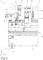
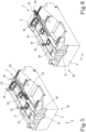
- Figure 3 shows the auxiliary system 7, for example, in the inactive configuration, in the proximal zone of the working area 3
- Figure 4 shows the auxiliary system 7, for example, in the active configuration in the distal zone of the working area 3, after the movement along the transverse axis Y has been completed.
- This movement may be manual and may be carried out by the operator using, for example, a rod or extension to make it easier for the operator to move the auxiliary system 7 along the transverse axis Y.
- the movement may be automatic and carried out, for example, by a transverse actuator 74 driven by the operator, for example using a control, in particular a control located in proximity to the operator side 30.
- the auxiliary system 7 may comprise the longitudinal reference stop 72.
- the auxiliary system 7 may comprise the transverse reference stop 34.
- the gripper 71 or the locking suction cups 75 may be coupled to a support 73 movable along the transverse axis Y.
- the support 73 may thus act as support and linear guide parallel to the transverse axis Y.
- the support 73 may be coupled, for example, to the bed 2 or to one of the plurality of bars 31.
- the auxiliary system 7 may be disposed, for example, at a transverse side of the working area 3, parallel to the transverse axis Y, as shown, for example, in Figures 2 , 3 and 4 . That way, the machine 1 is constructionally simpler and less subject to breakdowns.
- the raiser 32 may extend along the transverse axis Y and be disposed in the working area 3 in such a way as to be spaced from the auxiliary system 7 along the longitudinal axis X. That way, the auxiliary system 7 and the raiser 32, or the plurality of raisers 32, may act in conjunction to support the panel P, in particular when the auxiliary system 7 is in the active configuration and the raiser 32, or the raisers 32, is/are at the raised position. This allows panels of different sizes to be supported in a flexible, optimum manner.
- the machine 1 may comprise a plurality of auxiliary systems 7.
- each auxiliary system 7 of the plurality of auxiliary systems 7 may be coupled, movably along the vertical axis Z, to a respective raiser 32 of the plurality of raisers 32. That way, the machine 1 is flexible in that loading panels of different shapes and sizes is made easier.
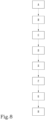
- the letter A in Figure 8 denotes the step of moving the raiser 32 from the lowered position to the raised position.
- one or more raisers 32 may be moved. This movement may be carried out using a control, operated by the operator, for example.
- the control may be located, for example, in proximity to the operator side 30 so as to facilitate access to it. If the raisers 32 have a first raiser 32' and a second raiser 32", these may both be moved to the raised position by means of the first actuator 321' and the second actuator 321", respectively.
- the panel P to be machined is rested by the operator on the raisers 32 at the raised position, in particular in the proximal zone of the working area 3.
- This step is labelled B in Figure 6 .
- the operator may rest the panel P also on the auxiliary system 7, positioned in the proximal zone of the working area 3.
- the auxiliary system 7 may pass from the inactive configuration to the active configuration.
- This step is labelled D in Figure 6 .
- the locking gripper 71 or the locking suction cup 75 grip and lock the panel P securely to them.
- the locking gripper 71 grips the panel P with the upper jaw 711 and the lower jaw 712.
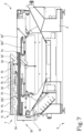
- the locking suction cup 75 moves upwards along the vertical axis Z until it comes into contact with the panel P. Once in contact, the negative pressure of the locking suction cup 75 is activated so as to hold the panel P securely against the locking suction cup 75.
- the letter E denotes the step of moving the auxiliary system 7 along the transverse axis Y from the proximal zone to the distal zone of the working area 3.
- This movement may be carried out manually by the operator or automatically by the transverse actuator 74. In the latter case, the operator may, for example, activate the transverse actuator 74 with a control which is located in proximity to the operator side 30 for easier access to it.
- This step of moving is denoted by the letter E in Figure 6 .
- the raiser 32 extends along the transverse axis Y and supports the panel P during the entire step of moving the auxiliary system 7 along the transverse axis Y from the proximal zone to the distal zone of the working area 3. That way, the panel P rests on several different points (auxiliary system 7 and one or more raisers 32), so that panels of different sizes can be moved safely without being damaged on account of their weight.
- the raisers 32 can be moved to the lowered position to bring the panel P into contact with the supporting suction cups, which are designed to support and hold the panel P in place while it is being machined. This step is labelled F in Figure 6 .
- step F i.e. during step E, the operator may rest a second panel P on the raisers 32, which are at the raised position, in the proximal zone of the working area 3, so as to advantageously speed up loading operations.
- the raisers 32 have a first raiser 32' and a second raiser 32"
- only the second raisers 32" may be moved from the raised position to the lowered position while the step F is in progress. That way, with the first raisers 32' still in the raised position, the operator can place another panel P in the proximal zone of the working area 3 even while the step F is in progress.
- the panel may then be locked in place in the working plane by the supporting suction cup 33 located in the distal zone of the working area 3. This step is labelled G in Figure 6 .
- the auxiliary system 7 may be passed from the active configuration to the inactive configuration so as to release the panel P to be machined. This step is labelled H in Figure 6 .
Landscapes
- Engineering & Computer Science (AREA)
- Mechanical Engineering (AREA)
- Life Sciences & Earth Sciences (AREA)
- Wood Science & Technology (AREA)
- Forests & Forestry (AREA)
- Feeding Of Workpieces (AREA)
Applications Claiming Priority (1)
| Application Number | Priority Date | Filing Date | Title |
|---|---|---|---|
| IT102023000025992A IT202300025992A1 (it) | 2023-12-05 | 2023-12-05 | Macchina per la lavorazione di un pannello e metodo per la lavorazione di un pannello |
Publications (1)
| Publication Number | Publication Date |
|---|---|
| EP4566780A1 true EP4566780A1 (de) | 2025-06-11 |
Family
ID=89845063
Family Applications (1)
| Application Number | Title | Priority Date | Filing Date |
|---|---|---|---|
| EP24217371.4A Pending EP4566780A1 (de) | 2023-12-05 | 2024-12-04 | Maschine zur bearbeitung einer platte und verfahren zur bearbeitung einer platte |
Country Status (2)
| Country | Link |
|---|---|
| EP (1) | EP4566780A1 (de) |
| IT (1) | IT202300025992A1 (de) |
Citations (6)
| Publication number | Priority date | Publication date | Assignee | Title |
|---|---|---|---|---|
| EP0465435B1 (de) * | 1990-06-25 | 1994-05-11 | ALBERTI VITTORIO S.p.A. | Mehrspindel-Werkzeugmaschine zur spanabhebenden Bearbeitung von Platten |
| US20030015001A1 (en) * | 2001-06-19 | 2003-01-23 | Bimatech S.R.L. | Method of setting a machine for machining a sheet of glass, and machine configurable thereby |
| DE102009017856B3 (de) * | 2009-04-17 | 2010-09-09 | Ima Klessmann Gmbh Holzbearbeitungssysteme | Trägereinrichtung |
| EP2842706A1 (de) | 2013-04-17 | 2015-03-04 | SCM Group S.p.A. | Vorrichtung für automatische Zufuhr und Pendelbearbeitung von Holzteilen |
| EP3804930A1 (de) | 2019-10-10 | 2021-04-14 | SCM Group S.p.A. | Bearbeitungscenter mit be- und entladesystem für werkstücke, be- und entladesystem für werkstücke und zugehöriges verfahren zu dessen betrieb |
| US20220379464A1 (en) * | 2019-11-10 | 2022-12-01 | Martin Zimmer | Production cell with at least two machining robots |
-
2023
- 2023-12-05 IT IT102023000025992A patent/IT202300025992A1/it unknown
-
2024
- 2024-12-04 EP EP24217371.4A patent/EP4566780A1/de active Pending
Patent Citations (6)
| Publication number | Priority date | Publication date | Assignee | Title |
|---|---|---|---|---|
| EP0465435B1 (de) * | 1990-06-25 | 1994-05-11 | ALBERTI VITTORIO S.p.A. | Mehrspindel-Werkzeugmaschine zur spanabhebenden Bearbeitung von Platten |
| US20030015001A1 (en) * | 2001-06-19 | 2003-01-23 | Bimatech S.R.L. | Method of setting a machine for machining a sheet of glass, and machine configurable thereby |
| DE102009017856B3 (de) * | 2009-04-17 | 2010-09-09 | Ima Klessmann Gmbh Holzbearbeitungssysteme | Trägereinrichtung |
| EP2842706A1 (de) | 2013-04-17 | 2015-03-04 | SCM Group S.p.A. | Vorrichtung für automatische Zufuhr und Pendelbearbeitung von Holzteilen |
| EP3804930A1 (de) | 2019-10-10 | 2021-04-14 | SCM Group S.p.A. | Bearbeitungscenter mit be- und entladesystem für werkstücke, be- und entladesystem für werkstücke und zugehöriges verfahren zu dessen betrieb |
| US20220379464A1 (en) * | 2019-11-10 | 2022-12-01 | Martin Zimmer | Production cell with at least two machining robots |
Also Published As
| Publication number | Publication date |
|---|---|
| IT202300025992A1 (it) | 2025-06-05 |
Similar Documents
| Publication | Publication Date | Title |
|---|---|---|
| EP1810803B1 (de) | Maschine zur Bearbeitung von Holzelementen mit automatischer Ladung und Entladung dieser Elemente sowie Verfahren zum Laden dieser Elemente | |
| KR101467861B1 (ko) | 공작 기계 | |
| US5407415A (en) | Automated composite trim workstation | |
| CN109843503B (zh) | 输送设备及其控制装置和材料加工单元的装载和卸载方法 | |
| EP1712337B1 (de) | Bearbeitungszentrum mit zwei Arbeitseinheiten mit Mitteln zur Handhabung des Werkstücks | |
| EP2067586A2 (de) | Holzbearbeitungsmaschine | |
| US20080181759A1 (en) | Workpiece handling device | |
| US12491623B2 (en) | Production cell with at least two machining robots | |
| KR102309360B1 (ko) | 가공물 자동 언로딩장치 | |
| CN112238266B (zh) | 数控滚齿机床 | |
| US12337429B2 (en) | Manufacturing cell comprising a tool carrier | |
| US20020151420A1 (en) | Worktable Apparatus | |
| FI3620422T3 (fi) | Kuljettajaton kuljetin | |
| US6606531B1 (en) | Sheet material loader/unloader for machine tools | |
| JPH071204A (ja) | 立旋盤 | |
| EP4566780A1 (de) | Maschine zur bearbeitung einer platte und verfahren zur bearbeitung einer platte | |
| CA3173595A1 (en) | Production cell with workpiece return | |
| EP3597359A1 (de) | Vorrichtung zum greifen von zu bearbeitenden dünnen platten in numerisch gesteuerten werkzeugmaschinen mit automatischer justierung, entsprechend hergestellte mehrspindelmaschine und verfahren zur bearbeitung dieser dünnen platten | |
| CN213593108U (zh) | 一种木器加工装置 | |
| CN107921546A (zh) | 工作机械 | |
| US11806922B2 (en) | CNC machining centre | |
| CN219853131U (zh) | 加工设备 | |
| CN211161707U (zh) | 一种用于滚丝机的上下料及调头装置 | |
| JP3911441B2 (ja) | ワーク受渡し装置 | |
| EP4461491B1 (de) | Vorrichtung und verfahren zur bearbeitung von länglichen werkstücken aus holz |
Legal Events
| Date | Code | Title | Description |
|---|---|---|---|
| PUAI | Public reference made under article 153(3) epc to a published international application that has entered the european phase |
Free format text: ORIGINAL CODE: 0009012 |
|
| STAA | Information on the status of an ep patent application or granted ep patent |
Free format text: STATUS: THE APPLICATION HAS BEEN PUBLISHED |
|
| AK | Designated contracting states |
Kind code of ref document: A1 Designated state(s): AL AT BE BG CH CY CZ DE DK EE ES FI FR GB GR HR HU IE IS IT LI LT LU LV MC ME MK MT NL NO PL PT RO RS SE SI SK SM TR |
|
| STAA | Information on the status of an ep patent application or granted ep patent |
Free format text: STATUS: REQUEST FOR EXAMINATION WAS MADE |
|
| GRAP | Despatch of communication of intention to grant a patent |
Free format text: ORIGINAL CODE: EPIDOSNIGR1 |
|
| STAA | Information on the status of an ep patent application or granted ep patent |
Free format text: STATUS: GRANT OF PATENT IS INTENDED |
|
| 17P | Request for examination filed |
Effective date: 20251202 |
|
| INTG | Intention to grant announced |
Effective date: 20251223 |
|
| GRAS | Grant fee paid |
Free format text: ORIGINAL CODE: EPIDOSNIGR3 |
|
| GRAA | (expected) grant |
Free format text: ORIGINAL CODE: 0009210 |
|
| STAA | Information on the status of an ep patent application or granted ep patent |
Free format text: STATUS: THE PATENT HAS BEEN GRANTED |