EP4566785A1 - Appareil de mélange - Google Patents
Appareil de mélange Download PDFInfo
- Publication number
- EP4566785A1 EP4566785A1 EP23214683.7A EP23214683A EP4566785A1 EP 4566785 A1 EP4566785 A1 EP 4566785A1 EP 23214683 A EP23214683 A EP 23214683A EP 4566785 A1 EP4566785 A1 EP 4566785A1
- Authority
- EP
- European Patent Office
- Prior art keywords
- container
- mixing
- mixing apparatus
- building material
- compartment
- Prior art date
- Legal status (The legal status is an assumption and is not a legal conclusion. Google has not performed a legal analysis and makes no representation as to the accuracy of the status listed.)
- Pending
Links
Images

Classifications
-
- B—PERFORMING OPERATIONS; TRANSPORTING
- B28—WORKING CEMENT, CLAY, OR STONE
- B28C—PREPARING CLAY; PRODUCING MIXTURES CONTAINING CLAY OR CEMENTITIOUS MATERIAL, e.g. PLASTER
- B28C5/00—Apparatus or methods for producing mixtures of cement with other substances, e.g. slurries, mortars, porous or fibrous compositions
- B28C5/08—Apparatus or methods for producing mixtures of cement with other substances, e.g. slurries, mortars, porous or fibrous compositions using driven mechanical means affecting the mixing
- B28C5/10—Mixing in containers not actuated to effect the mixing
- B28C5/12—Mixing in containers not actuated to effect the mixing with stirrers sweeping through the materials, e.g. with incorporated feeding or discharging means or with oscillating stirrers
- B28C5/1238—Mixing in containers not actuated to effect the mixing with stirrers sweeping through the materials, e.g. with incorporated feeding or discharging means or with oscillating stirrers for materials flowing continuously through the mixing device and with incorporated feeding or discharging devices
- B28C5/1246—Mixing in containers not actuated to effect the mixing with stirrers sweeping through the materials, e.g. with incorporated feeding or discharging means or with oscillating stirrers for materials flowing continuously through the mixing device and with incorporated feeding or discharging devices with feeding devices
-
- B—PERFORMING OPERATIONS; TRANSPORTING
- B01—PHYSICAL OR CHEMICAL PROCESSES OR APPARATUS IN GENERAL
- B01F—MIXING, e.g. DISSOLVING, EMULSIFYING OR DISPERSING
- B01F27/00—Mixers with rotary stirring devices in fixed receptacles; Kneaders
- B01F27/60—Mixers with rotary stirring devices in fixed receptacles; Kneaders with stirrers rotating about a horizontal or inclined axis
- B01F27/625—Mixers with rotary stirring devices in fixed receptacles; Kneaders with stirrers rotating about a horizontal or inclined axis the receptacle being divided into compartments, e.g. with porous divisions
-
- B—PERFORMING OPERATIONS; TRANSPORTING
- B01—PHYSICAL OR CHEMICAL PROCESSES OR APPARATUS IN GENERAL
- B01F—MIXING, e.g. DISSOLVING, EMULSIFYING OR DISPERSING
- B01F27/00—Mixers with rotary stirring devices in fixed receptacles; Kneaders
- B01F27/60—Mixers with rotary stirring devices in fixed receptacles; Kneaders with stirrers rotating about a horizontal or inclined axis
- B01F27/70—Mixers with rotary stirring devices in fixed receptacles; Kneaders with stirrers rotating about a horizontal or inclined axis with paddles, blades or arms
- B01F27/701—Mixers with rotary stirring devices in fixed receptacles; Kneaders with stirrers rotating about a horizontal or inclined axis with paddles, blades or arms comprising two or more shafts, e.g. in consecutive mixing chambers
- B01F27/702—Mixers with rotary stirring devices in fixed receptacles; Kneaders with stirrers rotating about a horizontal or inclined axis with paddles, blades or arms comprising two or more shafts, e.g. in consecutive mixing chambers with intermeshing paddles
-
- B—PERFORMING OPERATIONS; TRANSPORTING
- B01—PHYSICAL OR CHEMICAL PROCESSES OR APPARATUS IN GENERAL
- B01F—MIXING, e.g. DISSOLVING, EMULSIFYING OR DISPERSING
- B01F35/00—Accessories for mixers; Auxiliary operations or auxiliary devices; Parts or details of general application
- B01F35/20—Measuring; Control or regulation
- B01F35/21—Measuring
- B01F35/211—Measuring of the operational parameters
- B01F35/2112—Level of material in a container or the position or shape of the upper surface of the material
-
- B—PERFORMING OPERATIONS; TRANSPORTING
- B01—PHYSICAL OR CHEMICAL PROCESSES OR APPARATUS IN GENERAL
- B01F—MIXING, e.g. DISSOLVING, EMULSIFYING OR DISPERSING
- B01F35/00—Accessories for mixers; Auxiliary operations or auxiliary devices; Parts or details of general application
- B01F35/20—Measuring; Control or regulation
- B01F35/21—Measuring
- B01F35/211—Measuring of the operational parameters
- B01F35/2117—Weight
-
- B—PERFORMING OPERATIONS; TRANSPORTING
- B01—PHYSICAL OR CHEMICAL PROCESSES OR APPARATUS IN GENERAL
- B01F—MIXING, e.g. DISSOLVING, EMULSIFYING OR DISPERSING
- B01F35/00—Accessories for mixers; Auxiliary operations or auxiliary devices; Parts or details of general application
- B01F35/20—Measuring; Control or regulation
- B01F35/22—Control or regulation
- B01F35/221—Control or regulation of operational parameters, e.g. level of material in the mixer, temperature or pressure
- B01F35/2211—Amount of delivered fluid during a period
-
- B—PERFORMING OPERATIONS; TRANSPORTING
- B28—WORKING CEMENT, CLAY, OR STONE
- B28C—PREPARING CLAY; PRODUCING MIXTURES CONTAINING CLAY OR CEMENTITIOUS MATERIAL, e.g. PLASTER
- B28C5/00—Apparatus or methods for producing mixtures of cement with other substances, e.g. slurries, mortars, porous or fibrous compositions
- B28C5/08—Apparatus or methods for producing mixtures of cement with other substances, e.g. slurries, mortars, porous or fibrous compositions using driven mechanical means affecting the mixing
- B28C5/10—Mixing in containers not actuated to effect the mixing
- B28C5/12—Mixing in containers not actuated to effect the mixing with stirrers sweeping through the materials, e.g. with incorporated feeding or discharging means or with oscillating stirrers
- B28C5/1238—Mixing in containers not actuated to effect the mixing with stirrers sweeping through the materials, e.g. with incorporated feeding or discharging means or with oscillating stirrers for materials flowing continuously through the mixing device and with incorporated feeding or discharging devices
- B28C5/1253—Mixing in containers not actuated to effect the mixing with stirrers sweeping through the materials, e.g. with incorporated feeding or discharging means or with oscillating stirrers for materials flowing continuously through the mixing device and with incorporated feeding or discharging devices with discharging devices
-
- B—PERFORMING OPERATIONS; TRANSPORTING
- B28—WORKING CEMENT, CLAY, OR STONE
- B28C—PREPARING CLAY; PRODUCING MIXTURES CONTAINING CLAY OR CEMENTITIOUS MATERIAL, e.g. PLASTER
- B28C5/00—Apparatus or methods for producing mixtures of cement with other substances, e.g. slurries, mortars, porous or fibrous compositions
- B28C5/08—Apparatus or methods for producing mixtures of cement with other substances, e.g. slurries, mortars, porous or fibrous compositions using driven mechanical means affecting the mixing
- B28C5/10—Mixing in containers not actuated to effect the mixing
- B28C5/12—Mixing in containers not actuated to effect the mixing with stirrers sweeping through the materials, e.g. with incorporated feeding or discharging means or with oscillating stirrers
- B28C5/1238—Mixing in containers not actuated to effect the mixing with stirrers sweeping through the materials, e.g. with incorporated feeding or discharging means or with oscillating stirrers for materials flowing continuously through the mixing device and with incorporated feeding or discharging devices
- B28C5/1292—Mixing in containers not actuated to effect the mixing with stirrers sweeping through the materials, e.g. with incorporated feeding or discharging means or with oscillating stirrers for materials flowing continuously through the mixing device and with incorporated feeding or discharging devices with rotating stirring and feeding or discharging means fixed on the same axis, e.g. in an inclined container fed at its lower part
-
- B—PERFORMING OPERATIONS; TRANSPORTING
- B28—WORKING CEMENT, CLAY, OR STONE
- B28C—PREPARING CLAY; PRODUCING MIXTURES CONTAINING CLAY OR CEMENTITIOUS MATERIAL, e.g. PLASTER
- B28C5/00—Apparatus or methods for producing mixtures of cement with other substances, e.g. slurries, mortars, porous or fibrous compositions
- B28C5/08—Apparatus or methods for producing mixtures of cement with other substances, e.g. slurries, mortars, porous or fibrous compositions using driven mechanical means affecting the mixing
- B28C5/10—Mixing in containers not actuated to effect the mixing
- B28C5/12—Mixing in containers not actuated to effect the mixing with stirrers sweeping through the materials, e.g. with incorporated feeding or discharging means or with oscillating stirrers
- B28C5/14—Mixing in containers not actuated to effect the mixing with stirrers sweeping through the materials, e.g. with incorporated feeding or discharging means or with oscillating stirrers the stirrers having motion about a horizontal or substantially horizontal axis
- B28C5/145—Mixing in containers not actuated to effect the mixing with stirrers sweeping through the materials, e.g. with incorporated feeding or discharging means or with oscillating stirrers the stirrers having motion about a horizontal or substantially horizontal axis with several mixing chambers arranged one after the other
-
- B—PERFORMING OPERATIONS; TRANSPORTING
- B28—WORKING CEMENT, CLAY, OR STONE
- B28C—PREPARING CLAY; PRODUCING MIXTURES CONTAINING CLAY OR CEMENTITIOUS MATERIAL, e.g. PLASTER
- B28C5/00—Apparatus or methods for producing mixtures of cement with other substances, e.g. slurries, mortars, porous or fibrous compositions
- B28C5/08—Apparatus or methods for producing mixtures of cement with other substances, e.g. slurries, mortars, porous or fibrous compositions using driven mechanical means affecting the mixing
- B28C5/10—Mixing in containers not actuated to effect the mixing
- B28C5/12—Mixing in containers not actuated to effect the mixing with stirrers sweeping through the materials, e.g. with incorporated feeding or discharging means or with oscillating stirrers
- B28C5/14—Mixing in containers not actuated to effect the mixing with stirrers sweeping through the materials, e.g. with incorporated feeding or discharging means or with oscillating stirrers the stirrers having motion about a horizontal or substantially horizontal axis
- B28C5/146—Mixing in containers not actuated to effect the mixing with stirrers sweeping through the materials, e.g. with incorporated feeding or discharging means or with oscillating stirrers the stirrers having motion about a horizontal or substantially horizontal axis with several stirrers with parallel shafts in one container
-
- B—PERFORMING OPERATIONS; TRANSPORTING
- B28—WORKING CEMENT, CLAY, OR STONE
- B28C—PREPARING CLAY; PRODUCING MIXTURES CONTAINING CLAY OR CEMENTITIOUS MATERIAL, e.g. PLASTER
- B28C5/00—Apparatus or methods for producing mixtures of cement with other substances, e.g. slurries, mortars, porous or fibrous compositions
- B28C5/08—Apparatus or methods for producing mixtures of cement with other substances, e.g. slurries, mortars, porous or fibrous compositions using driven mechanical means affecting the mixing
- B28C5/10—Mixing in containers not actuated to effect the mixing
- B28C5/12—Mixing in containers not actuated to effect the mixing with stirrers sweeping through the materials, e.g. with incorporated feeding or discharging means or with oscillating stirrers
- B28C5/14—Mixing in containers not actuated to effect the mixing with stirrers sweeping through the materials, e.g. with incorporated feeding or discharging means or with oscillating stirrers the stirrers having motion about a horizontal or substantially horizontal axis
- B28C5/148—Mixing in containers not actuated to effect the mixing with stirrers sweeping through the materials, e.g. with incorporated feeding or discharging means or with oscillating stirrers the stirrers having motion about a horizontal or substantially horizontal axis the stirrer shaft carrying a plurality of radially extending mixing bars
-
- B—PERFORMING OPERATIONS; TRANSPORTING
- B28—WORKING CEMENT, CLAY, OR STONE
- B28C—PREPARING CLAY; PRODUCING MIXTURES CONTAINING CLAY OR CEMENTITIOUS MATERIAL, e.g. PLASTER
- B28C7/00—Controlling the operation of apparatus for producing mixtures of clay or cement with other substances; Supplying or proportioning the ingredients for mixing clay or cement with other substances; Discharging the mixture
- B28C7/02—Controlling the operation of the mixing
Definitions
- the present disclosure relates to a building material mixing apparatus, and especially to functional components of a mixing container.
- measuring the component materials in e.g. front loader scoops is not very accurate and can lead to inconsistencies when it comes to the mixed product.
- a building material mixer Since the purpose of a building material mixer is to mix building materials, it is crucial that it does its job well and consistently meaning that the material extracted from it should be evenly mixed and not have heterogenous concentrations of the component materials. Ideally, the mixer should be able to reproduce a finished mixed product consistently given the same input materials.
- a mixing apparatus for mixing building materials, the mixing apparatus comprising: a container comprising mixing members, characterized by the container comprising a mixing space delimited into two compartments by a wall, the wall having an opening allowing the material being mixed to flow along a longitudinal extension of the container from a first compartment to a second compartment, the first compartment being where the components to be mixed enter the container, and the second compartment being where the mixed building material is extracted from the mixing container.
- the key concept of this invention is that the opening in the delimiting wall limits the flow of building materials being mixed from the first compartment to the second compartment thereby increasing the time the component materials spend in the first compartment, where they are mixed before they enter the second compartment where they may be extracted. Without this wall, it may be possible for some of the component materials to flow to the area where they are extracted before they are thoroughly mixed, thus compromising the product. Further, by separating the two compartments such that the building material to be mixed only passes through the opening when being moved from the first compartment to the second compartment, a more continuous mixing may be performed, also enabling a more continuous extraction of mixed building material.
- the wall may be arranged in a plane perpendicular to the axis of the longitudinal extension of the container. When in normal use, the longitudinal extension of the container may be in a substantially horizontal plane. Gravity would thereby not substantially affect the flow of the building material in the container.
- the mixing members may be attached to an axle, the axle being oriented along an axis of the longitudinal extension, the axle being configured to rotate around said axis during use.
- An advantage of this embodiment is that one primary movement, the rotation of the axle, may cause a plurality of mixing members to move relative to the building material. The building material may thereby be mixed at several locations at once.
- the mixing members may be configured to move the materials being mixed toward the area of extraction. This may be achieved by a combination of the shape of the mixing members and the way they move relative to the building material being mixed. This may for example be achieved by having mixing members formed in an angle to the axis of the longitudinal extension, such that building material being in contact with a particular mixing member is moved in direction towards the area of extraction. If the building material being mixed are such that it does not flow easily by nature, it may risk getting stuck in the first compartment for too long. Using mixing members directing the building material may mitigate this issue.
- the opening in the delimiting wall may have an area of between 100 and 3000 cm 2 , preferably between 500 and 2000 cm 2 , more preferably between 700 and 1500 cm 2 .
- the dimensions of the opening may influence the rate of flow of materials between the compartments mentioned above.
- a smaller opening may have a lower rate of flow compared to a larger, similarly shaped opening centered at the same location. Decreasing the size of the opening may cause the components of the building material to spend more time in the first compartment before reaching the extraction area. A smaller opening may therefore cause the building material to be mixed for a longer time before being extracted.
- the building material being mixed is such that it does not flow easily by nature, a small opening may cause them to get stuck in in the first compartment for too long after being well mixed and ready for extraction. In such case a small opening may limit the rate of production of extractable material and a larger opening may be desired.
- the size of the opening may be based on the type of building material to be mixed. In one embodiment, the size of the opening may be adjustable.
- the size of the opening in the delimiting wall may be expressed in percent of the total area of the delimiting wall.
- the opening may have a size corresponding to less than 30%, less than 20% or less than 10% of the total area of the delimiting wall.
- the opening may be located in a lower portion of the delimiting wall.
- “Lower portion of the delimiting wall” may refer to the general area of the delimiting wall that would be in contact with the building material in the mixing container if said container would only be partially full. Partially full may mean, for example if the surface level of the building material is lower than the axle mentioned in a previous embodiment. If the surface level of the building material being mixed is below the openings lowest point, there will be no flow into the second compartment, and a portion of the components may be stuck in the first compartment. Therefore there may be an advantage of having the opening in the lower part of the wall.
- the container may have a bottom surface, and the opening may be arranged adjacent said bottom surface.
- the opening may be arranged adjacent said bottom surface.
- the mixing members may be attached to an axle, the axle being oriented along an axis of the longitudinal extension, the axle being configured to rotate around said axis during use, wherein the shape of the container is such that the mixing member's radially most distant part from the longitudinal axis of the axle around which it may rotate is essentially flush against the inside of the container for a part of the rotation. During this part of the rotation, little to no material may flow around the mixing member on the side that is very close to the containers inner wall, thus displacing more material compared to if it was allowed to flow around the mixing member to a larger extent. This may improve the directing of the flow of the building material to be mixed.
- the components of the building material may be configured to enter the container by means of an automatic feeding system.
- An example of such an automatic feeding system may be implemented using one or more conveyer belts configured to transport the respective right proportions of component material from storage containers, where said components may be transported to the first compartment of the container. This may improve the control of the relative proportions of the components of the building material as well as provide a more even, continuous influx to the container compared to loading the container with e.g. front loaders in batches.
- the mixing apparatus may comprise a sensor unit configured to be used for control of the influx of building material components to the container.
- a sensor unit configured to be used for control of the influx of building material components to the container.
- the advantage of having a sensor unit that measures a parameter relating to the state of the mixing apparatus is that the desired influx of component materials may depend on this parameter. By knowing the value of this parameter, the influx of component materials may be adjusted accordingly. E.g. reducing the influx when the amount of material in the container is above an upper threshold and increasing the influx when the amount of material in the container is below a lower threshold. If the amount of building material to be mixed in the container is too low, there may be a risk that building material moves to the second compartment and the area of extraction before it is completely mixed.
- the sensor unit may further be used for control of the extraction of mixed building material at the area of extraction. E.g. if the amount of material in the container is below the lower threshold, extraction of material at the area of extraction may be disabled. The extraction of material may thereafter again be enabled when the amount of material in the container is above a third threshold being between the first and second thresholds.
- the sensor unit may be configured to measure the amount of building material in the container.
- the measured amount of building material in the container may be used for controlling the influx of component materials and/or extraction of mixed material as discussed above.
- the sensor unit may be configured to measure the weight of the container.
- An advantage of a weight sensor is that it may give a meaningful reading even though the contents in the container may not be evenly distributed.
- the sensor unit may be configured to measure the surface level of the building material in the container.
- An advantage of a sensor that measures the surface level of the building material in order to determine the amount of material in the container may be that it does not depend on the density of the contents.
- the relative positioning of the influx of the components with respect to each other and to the container may be such that they enter the mixing container at the first compartments half associated with its distal side with respect to the delimiting wall.
- the relative location of the influx of the components with respect to each other and the container may lead to different mixing properties. For example in the case where the components of concrete are being mixed, a better result may be achieved when all component materials enter the container at the first compartment's distal side relative to the delimiting wall.
- the component water enters the container at the first compartment's proximal side relative to the delimiting wall and the remaining component materials enter the container at the first compartment's distal side relative to the delimiting wall, an undesired effect may occur; the water may flow straight through the opening into the second compartment while the remaining, solid and granulated component materials remain in the first compartment. If the user were to extract the contents from the second compartment in this situation, they would receive a compromised product.
- the building material to be mixed may be concrete, and the component water may be entered into the first compartment at a location closer to the delimiting wall than the other components.
- the building material to be mixed may be concrete. While most of the description above refers to the mixing apparatus being used for mixing concrete on building sites, it may also be used within the field of land preparation. On building sites dealing with land preparation, sometimes specific mixtures of e.g. soil, sand and gravel may be needed, or other building material comprising solid, semisolid or liquid components.
- the mixing apparatus may be applied in this scenario, however the size of the opening in the delimiting wall might need to be adjusted.
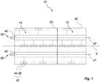
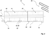
- the invention comprises a mixing apparatus comprising a container 10 having a longitudinal extension along a longitudinal axis X.
- the container is delimited by a delimiting wall 20 having at least one opening 22.
- the delimiting wall 20 comprises two openings 22, as seen in fig. 3 .
- the delimiting wall 20 forms a first compartment 12 and a second compartment 14 of the container 10.
- the opening 22 in the delimiting wall 20 limits the rate of flow of material from the first compartment 12 where the material components to be mixed enter the container and the second compartment 14 where the mixed material is extracted. This ensures that the material components have spent enough time being mixed before being extracted, thereby improving the homogeneity of the extracted building material.
- the first compartment 12 comprises moving mixing members 42 configured to mix the component building materials.
- the second compartment 14 also comprises moving mixing members 42. This ensures that the mixed building material is being mixed until extracted. In the case where the building material is e.g. concrete, this allows for a buffer of material ready for extraction, since the mixing prevents the concrete from solidifying.
- the second compartment 14, which contains the mixed building material during use, is larger than the first compartment 12. Delimiting the container 10 in this way allows for a larger proportion of mixed material ready for extraction to material being mixed.
- a rotatable axle 40 extending along the direction of the axis of the containers elongation X through the delimiting wall 20.
- the embodiment disclosed in Figs. 1-3 comprises a dual setup comprising two of these rotatable axles 40 with mounted mixing members 42. These two axles 40 rotate around their central axis, a1 and a2 respectively, during use.
- the mixing members 42 have a portion 46 configured to direct the material being mixed in a direction toward the area of extraction 60.
- the mixing members 42 has an elongated member 44. This elongated member extends in a substantially radially outward direction from the axis around which it rotates, a1 or a2.
- the portion 46 is attached to the end of this elongated member 44.
- the elongated members 44 are typically formed as arms extending between the respective axle 40 and the mixing portions 46.
- the shape of the container 10 is such that the mixing members' 46 radially most distant point 50 from the axis a1, a2 about which they rotate is essentially flush against the container's inner wall 30 for a segment of the revolution. In this embodiment, this segment is between points p1 and p2, as seen in fig. 3 .
- There are two openings 22 in the delimiting wall 20 of the embodiment in fig.3 one on each side associated with each valley in the bottom part of the container's wall 30.
- openings 22 are such that their bottom side is essentially flush against the lowest part of the valley they are associated with. This low positioning of the openings 22 in the delimiting wall 20 allows for reliable flow of building materials into the second compartment.
- having two openings as described above is more preferable compared to only having a single opening on one side since building material could get stuck in the valley without an opening.
- the area of the openings 22 in the embodiment shown in fig.3 are such that they are large enough to allow the contents of the first compartment 12 to flow through them into the second compartment 14 without getting stuck in the first compartment 12 and compromising the rate of production of mixed material, yet their area is not so large that they allow the materials being mixed to flow into the second compartment 14 before being ready for extraction.
- the illustrated embodiment also features two areas of extraction 60, as seen in fig.1 .
- the reason for this is essentially the same as to why the embodiment has two openings 22 in the delimiting wall, it is a consequence of the shape of the bottom side of the container's wall 30. They are located on the second compartment's distal wall with respect to the delimiting wall. There is one area of extraction 60 on each side associated with a valley. The location of these areas of extraction 60 are such that their bottom side is essentially flush against the lowest part of the valley of the side that they are on. If they were located higher on the same wall, material could not be extracted if the surface level of the contents of the second side were lower than lowest part of the area of extraction.
- the automatic feeding system features conveyer belts 80 that deliver an influx of component building materials at a desired location.
- the readings of the weight sensor are used as input data to this system to ensure that the contents of the container is kept within a certain range.
Landscapes
- Chemical & Material Sciences (AREA)
- Engineering & Computer Science (AREA)
- Mechanical Engineering (AREA)
- Structural Engineering (AREA)
- Chemical Kinetics & Catalysis (AREA)
- Dispersion Chemistry (AREA)
- Preparation Of Clay, And Manufacture Of Mixtures Containing Clay Or Cement (AREA)
Priority Applications (1)
| Application Number | Priority Date | Filing Date | Title |
|---|---|---|---|
| EP23214683.7A EP4566785A1 (fr) | 2023-12-06 | 2023-12-06 | Appareil de mélange |
Applications Claiming Priority (1)
| Application Number | Priority Date | Filing Date | Title |
|---|---|---|---|
| EP23214683.7A EP4566785A1 (fr) | 2023-12-06 | 2023-12-06 | Appareil de mélange |
Publications (1)
| Publication Number | Publication Date |
|---|---|
| EP4566785A1 true EP4566785A1 (fr) | 2025-06-11 |
Family
ID=89121663
Family Applications (1)
| Application Number | Title | Priority Date | Filing Date |
|---|---|---|---|
| EP23214683.7A Pending EP4566785A1 (fr) | 2023-12-06 | 2023-12-06 | Appareil de mélange |
Country Status (1)
| Country | Link |
|---|---|
| EP (1) | EP4566785A1 (fr) |
Citations (4)
| Publication number | Priority date | Publication date | Assignee | Title |
|---|---|---|---|---|
| JPS6120742U (ja) * | 1984-07-06 | 1986-02-06 | 東興建設株式会社 | コンクリ−ト類吹付機 |
| JPS62241534A (ja) * | 1986-04-14 | 1987-10-22 | Chisso Corp | 攪拌装置 |
| US5083506A (en) * | 1991-03-06 | 1992-01-28 | Blentech Corporation | Continuous compartmented mixer |
| DE20000435U1 (de) * | 2000-01-12 | 2001-05-23 | HILUTEC Systemtechnik GmbH & Co. KG, 48496 Hopsten | Vorrichtung zum Mischen von Komponenten |
-
2023
- 2023-12-06 EP EP23214683.7A patent/EP4566785A1/fr active Pending
Patent Citations (4)
| Publication number | Priority date | Publication date | Assignee | Title |
|---|---|---|---|---|
| JPS6120742U (ja) * | 1984-07-06 | 1986-02-06 | 東興建設株式会社 | コンクリ−ト類吹付機 |
| JPS62241534A (ja) * | 1986-04-14 | 1987-10-22 | Chisso Corp | 攪拌装置 |
| US5083506A (en) * | 1991-03-06 | 1992-01-28 | Blentech Corporation | Continuous compartmented mixer |
| DE20000435U1 (de) * | 2000-01-12 | 2001-05-23 | HILUTEC Systemtechnik GmbH & Co. KG, 48496 Hopsten | Vorrichtung zum Mischen von Komponenten |
Similar Documents
| Publication | Publication Date | Title |
|---|---|---|
| US6808303B2 (en) | Ready mix batch hauler system | |
| EP3265341B1 (fr) | Procédé et système permettant de déterminer la masse d'une charge dans un corps de benne basculante | |
| US3251484A (en) | Portable concrete batching plant | |
| WO2018052980A1 (fr) | Conteneur de stockage et de transport universel | |
| EP4566785A1 (fr) | Appareil de mélange | |
| US11346704B2 (en) | Load sensor bucket and related method | |
| EP4197320A1 (fr) | Mélangeur de fourrage comprenant un récipient de mélange pour fourrage et au moins un récipient supplémentaire pour complément alimentaire | |
| US2571113A (en) | Weighing and charging mechanism for transit mix trucks | |
| CN210544707U (zh) | 一种建筑用防水涂料配料装置 | |
| CN205951031U (zh) | 液压搅拌机 | |
| CN209407073U (zh) | 一种固态和液态修复药剂同时使用的土壤修复机 | |
| DE202020005601U1 (de) | Transportsystem zum Betonherstellen sowie Vorrichtung zur Durchführung eines Verfahrens zur mobilen Betonherstellung | |
| JP2001232167A (ja) | 粉粒体の攪拌混合装置 | |
| JP4104046B2 (ja) | アジテータトラックおよびアジテータトラックを使用したコンクリートの製造方法 | |
| EP2952312B1 (fr) | Dispositif mobile pour la preparation d'un melange de beton | |
| CN116971248A (zh) | 一体式道路固化土成型装置 | |
| CN208930492U (zh) | 一体化折叠式免基础车载移动搅拌站 | |
| US1998749A (en) | High discharge concrete mixer and method of operating the same | |
| US1380601A (en) | Dumping-truck | |
| DK2261612T3 (en) | A method and apparatus for direct measurement of a funnel | |
| US3139271A (en) | Custom mixing apparatus | |
| KR102616108B1 (ko) | 연속형 해양폐기물 자원순환 콘크리트 자동 배합 시스템 | |
| KR200488446Y1 (ko) | 그라우팅 배합기 | |
| KR102877385B1 (ko) | Srcm 플랜트 시스템 | |
| JP6235880B2 (ja) | 計量ホッパー |
Legal Events
| Date | Code | Title | Description |
|---|---|---|---|
| PUAI | Public reference made under article 153(3) epc to a published international application that has entered the european phase |
Free format text: ORIGINAL CODE: 0009012 |
|
| STAA | Information on the status of an ep patent application or granted ep patent |
Free format text: STATUS: THE APPLICATION HAS BEEN PUBLISHED |
|
| AK | Designated contracting states |
Kind code of ref document: A1 Designated state(s): AL AT BE BG CH CY CZ DE DK EE ES FI FR GB GR HR HU IE IS IT LI LT LU LV MC ME MK MT NL NO PL PT RO RS SE SI SK SM TR |
|
| STAA | Information on the status of an ep patent application or granted ep patent |
Free format text: STATUS: THE APPLICATION IS DEEMED TO BE WITHDRAWN |