EP4566843A1 - Pneumatique - Google Patents
Pneumatique Download PDFInfo
- Publication number
- EP4566843A1 EP4566843A1 EP24212677.9A EP24212677A EP4566843A1 EP 4566843 A1 EP4566843 A1 EP 4566843A1 EP 24212677 A EP24212677 A EP 24212677A EP 4566843 A1 EP4566843 A1 EP 4566843A1
- Authority
- EP
- European Patent Office
- Prior art keywords
- tire
- arc
- tread
- axial direction
- circumferential
- Prior art date
- Legal status (The legal status is an assumption and is not a legal conclusion. Google has not performed a legal analysis and makes no representation as to the accuracy of the status listed.)
- Granted
Links
Images

Classifications
-
- B—PERFORMING OPERATIONS; TRANSPORTING
- B60—VEHICLES IN GENERAL
- B60C—VEHICLE TYRES; TYRE INFLATION; TYRE CHANGING; CONNECTING VALVES TO INFLATABLE ELASTIC BODIES IN GENERAL; DEVICES OR ARRANGEMENTS RELATED TO TYRES
- B60C11/00—Tyre tread bands; Tread patterns; Anti-skid inserts
-
- B—PERFORMING OPERATIONS; TRANSPORTING
- B60—VEHICLES IN GENERAL
- B60C—VEHICLE TYRES; TYRE INFLATION; TYRE CHANGING; CONNECTING VALVES TO INFLATABLE ELASTIC BODIES IN GENERAL; DEVICES OR ARRANGEMENTS RELATED TO TYRES
- B60C11/00—Tyre tread bands; Tread patterns; Anti-skid inserts
- B60C11/0008—Tyre tread bands; Tread patterns; Anti-skid inserts characterised by the tread rubber
-
- B—PERFORMING OPERATIONS; TRANSPORTING
- B60—VEHICLES IN GENERAL
- B60C—VEHICLE TYRES; TYRE INFLATION; TYRE CHANGING; CONNECTING VALVES TO INFLATABLE ELASTIC BODIES IN GENERAL; DEVICES OR ARRANGEMENTS RELATED TO TYRES
- B60C11/00—Tyre tread bands; Tread patterns; Anti-skid inserts
- B60C11/0083—Tyre tread bands; Tread patterns; Anti-skid inserts characterised by the curvature of the tyre tread
-
- B—PERFORMING OPERATIONS; TRANSPORTING
- B60—VEHICLES IN GENERAL
- B60C—VEHICLE TYRES; TYRE INFLATION; TYRE CHANGING; CONNECTING VALVES TO INFLATABLE ELASTIC BODIES IN GENERAL; DEVICES OR ARRANGEMENTS RELATED TO TYRES
- B60C11/00—Tyre tread bands; Tread patterns; Anti-skid inserts
- B60C11/03—Tread patterns
- B60C11/0304—Asymmetric patterns
-
- B—PERFORMING OPERATIONS; TRANSPORTING
- B60—VEHICLES IN GENERAL
- B60C—VEHICLE TYRES; TYRE INFLATION; TYRE CHANGING; CONNECTING VALVES TO INFLATABLE ELASTIC BODIES IN GENERAL; DEVICES OR ARRANGEMENTS RELATED TO TYRES
- B60C11/00—Tyre tread bands; Tread patterns; Anti-skid inserts
- B60C11/03—Tread patterns
- B60C11/0327—Tread patterns characterised by special properties of the tread pattern
- B60C11/0332—Tread patterns characterised by special properties of the tread pattern by the footprint-ground contacting area of the tyre tread
-
- B—PERFORMING OPERATIONS; TRANSPORTING
- B60—VEHICLES IN GENERAL
- B60C—VEHICLE TYRES; TYRE INFLATION; TYRE CHANGING; CONNECTING VALVES TO INFLATABLE ELASTIC BODIES IN GENERAL; DEVICES OR ARRANGEMENTS RELATED TO TYRES
- B60C11/00—Tyre tread bands; Tread patterns; Anti-skid inserts
- B60C11/03—Tread patterns
- B60C11/13—Tread patterns characterised by the groove cross-section, e.g. for buttressing or preventing stone-trapping
- B60C11/1376—Three dimensional block surfaces departing from the enveloping tread contour
-
- B—PERFORMING OPERATIONS; TRANSPORTING
- B60—VEHICLES IN GENERAL
- B60C—VEHICLE TYRES; TYRE INFLATION; TYRE CHANGING; CONNECTING VALVES TO INFLATABLE ELASTIC BODIES IN GENERAL; DEVICES OR ARRANGEMENTS RELATED TO TYRES
- B60C11/00—Tyre tread bands; Tread patterns; Anti-skid inserts
- B60C11/0008—Tyre tread bands; Tread patterns; Anti-skid inserts characterised by the tread rubber
- B60C2011/0016—Physical properties or dimensions
-
- B—PERFORMING OPERATIONS; TRANSPORTING
- B60—VEHICLES IN GENERAL
- B60C—VEHICLE TYRES; TYRE INFLATION; TYRE CHANGING; CONNECTING VALVES TO INFLATABLE ELASTIC BODIES IN GENERAL; DEVICES OR ARRANGEMENTS RELATED TO TYRES
- B60C11/00—Tyre tread bands; Tread patterns; Anti-skid inserts
- B60C11/03—Tread patterns
- B60C2011/0337—Tread patterns characterised by particular design features of the pattern
- B60C2011/0339—Grooves
- B60C2011/0341—Circumferential grooves
-
- B—PERFORMING OPERATIONS; TRANSPORTING
- B60—VEHICLES IN GENERAL
- B60C—VEHICLE TYRES; TYRE INFLATION; TYRE CHANGING; CONNECTING VALVES TO INFLATABLE ELASTIC BODIES IN GENERAL; DEVICES OR ARRANGEMENTS RELATED TO TYRES
- B60C11/00—Tyre tread bands; Tread patterns; Anti-skid inserts
- B60C11/03—Tread patterns
- B60C2011/0337—Tread patterns characterised by particular design features of the pattern
- B60C2011/0339—Grooves
- B60C2011/0341—Circumferential grooves
- B60C2011/0353—Circumferential grooves characterised by width
-
- B—PERFORMING OPERATIONS; TRANSPORTING
- B60—VEHICLES IN GENERAL
- B60C—VEHICLE TYRES; TYRE INFLATION; TYRE CHANGING; CONNECTING VALVES TO INFLATABLE ELASTIC BODIES IN GENERAL; DEVICES OR ARRANGEMENTS RELATED TO TYRES
- B60C11/00—Tyre tread bands; Tread patterns; Anti-skid inserts
- B60C11/03—Tread patterns
- B60C2011/0337—Tread patterns characterised by particular design features of the pattern
- B60C2011/0339—Grooves
- B60C2011/0381—Blind or isolated grooves
-
- B—PERFORMING OPERATIONS; TRANSPORTING
- B60—VEHICLES IN GENERAL
- B60C—VEHICLE TYRES; TYRE INFLATION; TYRE CHANGING; CONNECTING VALVES TO INFLATABLE ELASTIC BODIES IN GENERAL; DEVICES OR ARRANGEMENTS RELATED TO TYRES
- B60C11/00—Tyre tread bands; Tread patterns; Anti-skid inserts
- B60C11/03—Tread patterns
- B60C2011/0337—Tread patterns characterised by particular design features of the pattern
- B60C2011/0386—Continuous ribs
- B60C2011/0388—Continuous ribs provided at the equatorial plane
-
- B—PERFORMING OPERATIONS; TRANSPORTING
- B60—VEHICLES IN GENERAL
- B60C—VEHICLE TYRES; TYRE INFLATION; TYRE CHANGING; CONNECTING VALVES TO INFLATABLE ELASTIC BODIES IN GENERAL; DEVICES OR ARRANGEMENTS RELATED TO TYRES
- B60C11/00—Tyre tread bands; Tread patterns; Anti-skid inserts
- B60C11/03—Tread patterns
- B60C2011/0337—Tread patterns characterised by particular design features of the pattern
- B60C2011/0386—Continuous ribs
- B60C2011/039—Continuous ribs provided at the shoulder portion
Definitions
- the present invention relates to a pneumatic tire.
- Japanese Laid-Open Patent Publication No. 2019-14312 discloses a pneumatic tire in which an outer surface of a tread portion on a tire meridional cross-section is specified.
- the tire includes a crown arc extending across the tire equator, middle arcs connected to the crown arc, and shoulder arcs connected to the middle arcs.
- the first radius TR1 of curvature of the crown arc, the second radius TR2 of curvature of the middle arc, and the third radius TR3 of curvature of the shoulder arc satisfy TR1>TR2>TR3. It is considered that the tire having such a configuration allows uneven wear of the tread portion to be effectively reduced.
- a load higher than 100% of a load index may act on a tire.
- a ground contact pressure may locally become high in a region near the tread end depending on a profile of the tread portion, so that uneven wear may occur in the region or a cornering force may be lowered.
- the present invention has been made in view of the aforementioned problem, and an object of the present invention is to provide a pneumatic tire that allows enhancement of uneven wear resistance and dry grip performance.
- the present invention is directed to a pneumatic tire including a tread portion.
- the tread portion includes a first profile extending from a tire equator toward a first tread end on a tire meridional cross-section in a standardized state.
- the first profile includes a first arc extending outward from the tire equator in a tire axial direction, a second arc which is connected to the first arc and extends outward in the tire axial direction, a third arc which is connected to the second arc and extends outward in the tire axial direction, and a second connection point at which the second arc and the third arc are connected to each other.
- Each of the first arc, the second arc, and the third arc has a single radius of curvature.
- a radius TR2 of curvature of the second arc is 30% to 40% of a radius TR1 of curvature of the first arc.
- a radius TR3 of curvature of the third arc is 25% to 40% of the radius TR2 of curvature of the second arc.
- the second connection point is disposed inward of the first tread end in the tire axial direction.
- a distance by which the second connection point and the tire equator are distant in the tire axial direction is 30% to 34% of a cross-sectional width of the tire.
- the third arc extends outward in the tire axial direction beyond the first tread end.
- the pneumatic tire of the present invention has the above-described configuration, and can thus enhance uneven wear resistance and dry grip performance.
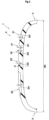
- FIG. 1 is a tire meridional cross-sectional view, including a tire rotation axis (not shown), of a pneumatic tire (hereinafter, may be simply referred to as "tire") 1 of the present embodiment in a standardized state.
- the present invention is suitably applied to, for example, a tire, for a passenger car, which allows running on a circuit in a race. With such a tire 1, running may be performed at a relatively high speed, so that a load higher than 100% of a load index may act during the running.
- the "load index” refers to an index that is defined by the JATMA standard and represents a maximum mass allowed to be applied to a tire under a specified condition, that is, a maximum load capacity as an index number.
- the tire 1 of the present invention is not limited to such a tire as to allow running in a race.
- the "standardized state” refers to a state in which the tire 1 is mounted on a standardized rim (not shown) and adjusted to be inflated to a standardized internal pressure, and no load is applied to the tire 1.
- dimensions of components of the tire 1 are represented by values measured in the standardized state.
- the "standardized rim” refers to a rim that is defined, in a standard system including a standard on which the tire 1 is based, by the standard for each tire, and is, for example, “standard rim” in the JATMA standard, "Design Rim” in the TRA standard, or “Measuring Rim” in the ETRTO standard.
- the "standardized internal pressure” refers to an air pressure that is defined, in a standard system including a standard on which the tire 1 is based, by the standard for each tire, and is "maximum air pressure” in the JATMA standard, the maximum value recited in the table "TIRE LOAD LIMITS AT VARIOUS COLD INFLATION PRESSURES" in the TRA standard, or "INFLATION PRESSURE” in the ETRTO standard.
- the tire 1 has a tread portion 2.
- the tire 1 further includes a pair of sidewall portions 3 connected to both sides of the tread portion 2 in the tire axial direction.
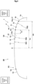
- FIG. 2 shows a profile of the tread portion 2 of the present embodiment.
- the profile represents a contour 1a obtained by filling recesses provided at the surface of the tire 1 on the tire meridional cross-section in the standardized state.
- the recesses include circumferential grooves and lateral grooves described below.
- the tread portion 2 includes a first profile P1 extending from the tire equator C toward a first tread end T1.
- the first profile P1 includes a first arc 11, a second arc 12, a third arc 13, and a second connection point 15.
- the first arc 11 extends outward from the tire equator C in the tire axial direction.
- the second arc 12 is connected to the first arc 11 and extends outward in the tire axial direction.
- the third arc 13 is connected to the second arc 12 and extends outward in the tire axial direction.
- the second connection point 15 is a point at which the second arc 12 and the third arc 13 are connected to each other.
- the second connection point 15 is disposed inward of the first tread end T1 in the tire axial direction.
- the first arc 11, the second arc 12, and the third arc 13 have a single radius TR1 of curvature, a single radius TR2 of curvature, and a single radius TR3 of curvature, respectively.
- the radius TR2 of curvature of the second arc 12 is 30% to 40% of the radius TR1 of curvature of the first arc 11.
- the radius TR3 of curvature of the third arc 13 is 25% to 40% of the radius TR2 of curvature of the second arc 12.
- a distance La by which the second connection point 15 and the tire equator C are distant in the tire axial direction is 30% to 34% of a cross-sectional width Wt (shown in FIG. 1 ) of the tire 1.
- the third arc 13 extends outward in the tire axial direction beyond the first tread end T1.
- the first profile P1 having such a configuration allows the third arc 13 to smoothly come into contact with the ground and allows a ground contact region to be increased, outside the first tread end T1, in a running state in which the load is higher than 100% of the load index.
- Such increase of the ground-contact region inhibits a ground contact pressure from being locally increased near the first tread end T1, and allows uneven wear to be reduced near the first tread end T1 and inhibits a cornering force from being lowered.
- the cross-sectional width Wt represents the maximum width of the tire 1 in the tire axial direction as measured by excluding, for example, a rim guard (not shown) and patterns or characters at a tire side surface.
- the radius TR2 of curvature of the second arc 12 is preferably 32% or more and preferably 38% or less of the radius TR1 of curvature of the first arc 11.
- the radius TR3 of curvature of the third arc 13 is preferably 27% or more and preferably 38% or less of the radius TR2 of curvature of the second arc 12.
- the distance La by which the second connection point 15 and the tire equator C are distant in the tire axial direction is preferably 31% or more and preferably 33% or less of the cross-sectional width Wt.
- the first tread end T1 and a second tread end T2 described below are defined as ground contact positions at both ends in the tire axial direction in a state (hereinafter, referred to "standardized-load-applied state") in which a standardized load is applied to the tire 1 in the standardized state, and the tire 1 is brought into contact with a plane at a camber angle of 0°.
- the length in the tire axial direction between the first tread end T1 and the second tread end T2 is defined as a tread width TW (shown in FIG. 3 ).
- the "standardized load” refers to a load that is defined, in a standard system including a standard on which the tire is based, by the standard for each tire, and is "maximum load capacity" in the JATMA standard, the maximum value recited in the table "TIRE LOAD LIMITS AT VARIOUS COLD INFLATION PRESSURES" in the TRA standard, or "LOAD CAPACITY” in the ETRTO standard, for pneumatic tires for which various standards are defined.
- the first tread end T1 and the second tread end T2 can be considered to be both ends, in the tire axial direction, of the tread portion 2 which comes into contact with a plane in running at 100% of the load index.
- the first profile P1 further includes a first connection point 14, an outer arc 16, and a third connection point 17.
- the first connection point 14 is a point at which the first arc 11 and the second arc 12 are connected to each other.
- the outer arc 16 is connected to the third arc 13 and extends outward in the tire axial direction.
- the outer arc 16 is a region that is not assumed to come into contact with the ground even in running, such as running on a circuit in a race, in which the load is higher than 100% of the load index.
- the third connection point 17 is a point at which the outer arc 16 and the third arc 13 are connected to each other. On both sides of each of the first connection point 14, the second connection point 15, and the third connection point 17 in the tire axial direction, the radius of curvature is changed.
- a distance Lb by which an outer end 13e (coincides with the third connection point 17) of the third arc 13 in the tire axial direction and the tire equator C are distant in the tire axial direction is preferably 44% or more of the cross-sectional width Wt and more preferably 45% or more thereof, and preferably 48% or less thereof and more preferably 47% or less thereof. Since the distance Lb is 44% or more and 48% or less of the cross-sectional width Wt, the third arc 13 comes into contact with the ground and the outer arc 16 does not come into contact with the ground even in a running state in which the load is higher than 100% of the load index, so that a ground contact pressure can be inhibited from being locally increased.
- the tread portion 2 includes the second tread end T2 disposed on the side opposite to the first tread end T1 side.
- the tread portion 2 includes a second profile P2 extending from the tire equator C toward the second tread end T2.
- the second profile P2 and the first profile P1 are line-symmetric with respect to the tire equator C.
- the second profile P2 having such a configuration also allows the third arc 13 to smoothly come into contact with the ground and allows a ground contact region to be increased, outside the second tread end T2, in a running state in which the load is higher than 100% of the load index. Therefore, the tire 1 of the present embodiment has more excellent uneven wear resistance and dry grip performance.
- the second profile P2 and the first profile P1 may not necessarily be line-symmetric.
- the radius TR1 of curvature of the first arc 11 is preferably 600 mm or more and more preferably 700 mm or more, and preferably 1200 mm or less and more preferably 1100 mm or less. Since the radius TR1 of curvature is 600 mm or more and 1200 mm or less, the ground contact pressure can be made uniform from the first arc 11 to the third arc 13.
- the radius TR4 of curvature of the outer arc 16 is, but is not particularly limited to, preferably 15 mm or more and more preferably 20 mm or more, and preferably 45 mm or less and more preferably 40 mm or less.
- the tread portion 2 has a designated mounting direction to a vehicle.
- the first tread end T1 is an inner tread end disposed on the inner side of a vehicle when the tire is mounted to the vehicle.
- the second tread end T2 is an outer tread end disposed on the outer side of the vehicle when the tire is mounted to the vehicle.
- a portion of the tread portion 2 between the tire equator C and the first tread end T1 is defined as an inner tread portion 2A
- a portion of the tread portion 2 between the tire equator C and the second tread end T2 is defined as an outer tread portion 2B.
- a lateral force acting on the outer tread portion 2B is higher than a lateral force acting on the inner tread portion 2A during cornering.
- FIG. 3 is a plan view showing a development of the tread portion 2.
- the tread portion 2 has a plurality of circumferential grooves 20 extending in the tire circumferential direction.
- the plurality of circumferential grooves 20 include a first circumferential groove 21 closest to the first tread end T1.
- the first circumferential groove 21 is disposed so as to overlap the second arc 12 (shown in FIG. 2 ).
- a distance Lc by which an outer edge 21e of the first circumferential groove 21 in the tire axial direction and the second connection point 15 are distant in the tire axial direction is preferably 10 mm or more.
- the second connection point 15 at which the ground contact pressure may become high is distant from the first circumferential groove 21, so that uneven wear is inhibited from occurring near the first circumferential groove 21.
- the distance Lc is more preferably 15 mm or more, and preferably 30 mm or less and more preferably 25 mm or less.
- all of the plurality of the circumferential grooves 20 are disposed between the tire equator C and the first tread end T1 (inner tread end). In other words, all of the plurality of the circumferential grooves 20 are disposed in the inner tread portion 2A.
- stiffness of the outer tread portion 2B in the tire axial direction is maintained to be higher than stiffness of the inner tread portion 2A in the tire axial direction, so that the ground contact pressure is made uniform between the inner tread portion 2A and the outer tread portion 2B, and dry grip performance in cornering is enhanced.
- the plurality of circumferential grooves 20 include a second circumferential groove 22 disposed between the first circumferential groove 21 and the tire equator C.
- the plurality of circumferential grooves 20 are formed of the first circumferential groove 21 and the second circumferential groove 22.
- the plurality of circumferential grooves 20 may include, for example, another circumferential groove (not shown).
- each of the first circumferential groove 21 and the second circumferential groove 22 linearly extends in parallel with the tire circumferential direction.
- Each of an angle ⁇ 1 of a groove-width center line 21s of the first circumferential groove 21 relative to the tire circumferential direction, and an angle ⁇ 2 of a groove-width center line 22s of the second circumferential groove 22 relative to the tire circumferential direction is preferably 5° or less, and is 0° in the present embodiment.
- Each of a groove width W1 of the first circumferential groove 21 and a groove width W2 of the second circumferential groove 22 is preferably 4% or more of the tread width TW and more preferably 6% or more thereof, and preferably 14% or less thereof and more preferably 12% or less thereof.
- Each of a groove depth D1 (shown in FIG. 1 ) of the first circumferential groove 21 and a groove depth D2 of the second circumferential groove 22 is preferably 3 mm or more and more preferably 4 mm or more, and preferably 8 mm or less and more preferably 7 mm or less.
- the circumferential groove 20 having such a configuration allows enhancement of drainage performance while inhibiting stiffness of the tread portion 2 from being excessively reduced.
- the tread portion 2 includes a first land portion 24 demarcated by the first circumferential groove 21 and the first tread end T1, and a second land portion 25 demarcated by the second circumferential groove 22 and the second tread end T2.
- the tread portion 2 includes, for example, a third land portion 26 demarcated by the first circumferential groove 21 and the second circumferential groove 22.
- a tire axial width Wb of the second land portion 25 is set to be greater than a tire axial width Wc of the third land portion 26.
- the tire axial width Wc of the third land portion 26 is set to be greater than a tire axial width Wa of the first land portion 24.
- the tire axial width Wa of the first land portion 24 is, but is not particularly limited to, preferably 5% or more of the tread width TW and more preferably 10% or more thereof, and preferably less than 25% thereof and more preferably 20% or less thereof.
- the tire axial width Wb of the second land portion 25 is preferably 40% or more of the tread width TW and more preferably 45% or more thereof, and preferably 60% or less thereof and more preferably 55% or less thereof.
- the tire axial width Wc of the third land portion 26 is preferably greater than 5% of the tread width TW and more preferably 10% or more thereof, and preferably 25% or less thereof and more preferably 20% or less thereof.
- the first land portion 24 has a plurality of first lateral grooves 31 aligned at a first pitch length P11 in the tire circumferential direction.
- the second land portion 25 has a plurality of second lateral grooves 32 aligned at a second pitch length P12 in the tire circumferential direction.
- the second pitch length P12 is preferably greater than the first pitch length P11.
- Each of the first lateral groove 31 and the second lateral groove 32 extends in parallel with the tire axial direction.
- Each of an angle ⁇ 3 of a groove-width center line 31s of the first lateral groove 31 relative to the tire axial direction and an angle ⁇ 4 of a groove-width center line 32s of the second lateral groove 32 relative to the tire axial direction is preferably 5° or less, and is 0° in the present embodiment.
- the plurality of first lateral grooves 31 each include an inner end 31i, in the tire axial direction, which terminates in the first land portion 24 without connecting to the first circumferential groove 21, and are connected to the first tread end T1.
- the first lateral groove 31 having such a configuration allows enhancement of drainage performance while inhibiting stiffness of the first land portion 24 from being excessively reduced.
- a groove width W3 of the first lateral groove 31 is preferably 45% or more of the groove width W1 of the first circumferential groove 21 and more preferably 50% or more thereof, and preferably 65% or less thereof and more preferably 60% or less thereof.
- a groove depth D3 (shown in FIG. 1 ) of the first lateral groove 31 is preferably 80% or more of the groove depth D1 of the first circumferential groove 21 and more preferably 90% or more thereof, and preferably 120% or less thereof and more preferably 110% or less thereof.
- the first lateral groove 31 enhances drainage performance and dry grip performance in a well-balanced manner.
- a distance Ld by which the inner end 31i of the first lateral groove 31 and the outer edge 21e of the first circumferential groove 21 are distant in the tire axial direction is preferably 35% or more of the tire axial width Wa of the first land portion 24 and more preferably 40% or more thereof, and preferably 55% or less thereof and more preferably 50% or less thereof.
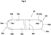
- FIG. 4 is a schematic enlarged view of the second lateral groove 32 in FIG. 3 .
- a groove edge 35 of each of the plurality of second lateral grooves 32 includes inner arc portions 35a each extending on the inner end 32i side so as to form an arc, and outer arc portions 35b each extending on the outer end 32e side so as to form an arc.
- Each groove edge 35 has the inner arc portions 35a distant from each other in the tire circumferential direction and the outer arc portions 35b distant from each other in the tire circumferential direction.
- the groove edge 35 includes a pair of axial portions 35c connecting between the inner arc portions 35a and the outer arc portions 35b, a first circumferential portion 35d extending in the tire circumferential direction so as to connect between the inner arc portions 35a, and a second circumferential portion 35e extending in the tire circumferential direction so as to connect between the outer arc portions 35b.
- the axial portions 35c and the circumferential portions 35d, 35e linearly extend.
- a state where the groove edge 35 linearly extends includes not only a state where the radius of curvature is infinite ( ⁇ ), but also a state where the groove edge 35 forms an arc having a radius of curvature of 400 mm or more, in a planar view of the tread.
- the outer arc portion 35b is disposed in a region (on the second tread end T2 side) on which a high lateral force acts during cornering. Therefore, a radius TR7 of curvature of the outer arc portion 35b is preferably greater than a radius TR6 of curvature of the inner arc portion 35a. Thus, stiffness of the outer tread portion 2B (shown in FIG. 3 ) on the second tread end T2 side is maintained to be high, so that uneven wear resistance is enhanced.
- the radius TR7 of curvature of the outer arc portion 35b is, but is not particularly limited to, preferably 110% or more of the radius TR6 of curvature of the inner arc portion 35a and more preferably 120% or more thereof, and preferably 300% or less thereof and more preferably 200% or less thereof.
- a groove width W4 of the second lateral groove 32 is preferably 55% or more of the groove width W2 (shown in FIG. 3 ) of the second circumferential groove 22 and more preferably 60% or more thereof, and preferably 75% or less thereof and more preferably 70% or less thereof.
- a groove depth D4 (shown in FIG. 1 ) of the second lateral groove 32 is preferably 80% or more of the groove depth D2 of the second circumferential groove 22 and more preferably 90% or more thereof, and preferably 120% or less thereof and more preferably 110% or less thereof.
- the distance Le is, but is not particularly limited to, preferably 10% or more of the tire axial width Wb of the second land portion 25 and more preferably 12% or more thereof, and preferably 20% or less thereof and more preferably 18% or less thereof.
- the distance Lf is preferably 4% or more of the tire axial width Wb of the second land portion 25 and more preferably 6% or more thereof, and preferably 12% or less thereof and more preferably 10% or less thereof.
- the third land portion 26 has a plurality of third lateral grooves 33 aligned at a third pitch length P13 in the tire circumferential direction.
- the third pitch length P13 is preferably less than the second pitch length P12.
- stiffness, in the tire circumferential direction, of the second land portion 25 disposed at the outer tread portion 2B is maintained to be higher than stiffness, in the tire circumferential direction, of the third land portion 26 disposed at the inner tread portion 2A. Therefore, a ground contact pressure is made uniform between the second land portion 25 and the third land portion 26. Accordingly, uneven wear resistance and dry grip performance are enhanced.
- the third pitch length P13 is, for example, equal to the first pitch length P11.
- the plurality of third lateral grooves 33 each include an inner end 33i, in the tire axial direction, which terminates in the third land portion 26 without connecting to the second circumferential groove 22, and are connected to the first circumferential groove 21.
- the third lateral groove 33 has a groove width W5 that is continuously increased toward the first circumferential groove 21.
- the third lateral groove 33 having such a configuration facilitates discharge of water in the third lateral groove 33 into the first circumferential groove 21, and inhibits stiffness of the third land portion 26 from being excessively reduced.
- a distance Lg by which the inner end 33i of the third lateral groove 33 and the second circumferential groove 22 are distant in the tire axial direction is preferably 50% or more of the tire axial width Wc of the third land portion 26 and more preferably 55% or more thereof, and preferably 70% or less thereof and more preferably 65% or less thereof.
- the distance Lg is 50% or more and 70% or less of the tire axial width Wc of the third land portion 26, so that drainage performance and dry grip performance can be enhanced in a well-balanced manner.
- a ratio (Lg/Wc) of the distance Lg to the tire axial width Wc of the third land portion 26 is greater than a ratio (Ld/Wa) of the distance Ld to the tire axial width Wa of the first land portion 24.
- a groove depth D5 of the third lateral groove 33 is preferably 80% or more of the groove depth D1 of the first circumferential groove 21 and more preferably 90% or more thereof, and preferably 120% or less thereof and more preferably 110% or less thereof.
- high drainage performance is exhibited.
- Pneumatic tires having the basic structure shown in FIG. 1 and the basic pattern shown in FIG. 3 were produced as test tires based on the specifications indicated in Table 1, and tested for dry grip performance, uneven wear resistance, and drainage performance.
- the main common matters were as follows.
- test tires of each example were mounted to all wheels of the following vehicle, and the vehicle was caused to run on a dry asphalt road surface in a circuit course and a wet asphalt road surface in a circuit course. During the running, a load higher than 100% of the load index acted on the tire.
- a test driver made sensory evaluation as to a degree of ease of running on the dry asphalt road surface in the circuit course, for dry grip performance.
- a test driver made sensory evaluation as to an uneven-wear generation state after running on the dry asphalt road surface in the circuit course, for uneven wear resistance.
- a test driver made sensory evaluation as to a degree of ease of running on the wet asphalt road surface in the circuit course, for drainage performance.
- the results are indicated as scores with the score of Comparative Example 1 being 100 in each test. The greater the value was, the better the result was.
- Tables 1 and 2 indicate the test results.
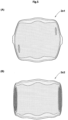
- FIG. 5(A) shows a ground contact pressure at a ground contact surface 2s 1 of the slick tire having a profile of Example 1 in a state where the load was 110% of the load index
- FIG. 5(B) shows a ground contact pressure at a ground contact surface 2s2 of the slick tire having a profile of Comparative example 1 in a state where the load was 110% of the load index.
- a higher-ground-contact-pressure portion is indicated by a darker color.
- the ground contact pressure was relatively uniform in the profile of Example 1 as compared with the profile of Comparative example 1.
- the present invention has the following aspects.
- a pneumatic tire including
- the pneumatic tire according to Invention 1 in which a distance by which an outer end of the third arc in the tire axial direction and the tire equator are distant in the tire axial direction is 44% to 48% of the cross-sectional width.
- the pneumatic tire according to Invention 1 or 2 in which the radius TR1 of curvature of the first arc is 600 to 1200 mm.
- the pneumatic tire according to Invention 8 in which the plurality of first lateral grooves each include an inner end, in the tire axial direction, which terminates in the first land portion without connecting to the first circumferential groove, and are connected to the first tread end.
- each of the plurality of second lateral grooves includes an inner end, in the tire axial direction, which terminates in the second land portion without connecting to the second circumferential groove.
- each of the plurality of second lateral grooves includes an outer end, in the tire axial direction, which terminates in the second land portion without connecting to the second tread end.
- a groove edge of each of the plurality of second lateral grooves includes an inner arc portion extending on the inner end side so as to form an arc, and an outer arc portion extending on the outer end side so as to form an arc, in a planar view of a tread.
- the pneumatic tire according to Invention 14 in which the plurality of third lateral grooves each include an inner end, in the tire axial direction, which terminates in the third land portion without connecting to the second circumferential groove, and are connected to the first circumferential groove.
Landscapes
- Engineering & Computer Science (AREA)
- Mechanical Engineering (AREA)
- Tires In General (AREA)
Applications Claiming Priority (1)
| Application Number | Priority Date | Filing Date | Title |
|---|---|---|---|
| JP2023205553A JP2025090359A (ja) | 2023-12-05 | 2023-12-05 | 空気入りタイヤ |
Publications (2)
| Publication Number | Publication Date |
|---|---|
| EP4566843A1 true EP4566843A1 (fr) | 2025-06-11 |
| EP4566843B1 EP4566843B1 (fr) | 2026-04-08 |
Family
ID=93521704
Family Applications (1)
| Application Number | Title | Priority Date | Filing Date |
|---|---|---|---|
| EP24212677.9A Active EP4566843B1 (fr) | 2023-12-05 | 2024-11-13 | Pneumatique |
Country Status (4)
| Country | Link |
|---|---|
| EP (1) | EP4566843B1 (fr) |
| JP (1) | JP2025090359A (fr) |
| KR (1) | KR20250085603A (fr) |
| CN (1) | CN120096241A (fr) |
Citations (6)
| Publication number | Priority date | Publication date | Assignee | Title |
|---|---|---|---|---|
| US5222537A (en) * | 1989-10-19 | 1993-06-29 | Sumitomo Rubber Industries, Ltd. | Stability pneumatic radial tire with high cornering and steering |
| US5803999A (en) * | 1996-02-14 | 1998-09-08 | Sumitomo Rubber Industries, Ltd. | Pneumatic radial tire with specified tread profile |
| DE19949064A1 (de) * | 1999-10-12 | 2001-04-26 | Continental Ag | Fahrzeugluftreifen |
| JP5917869B2 (ja) * | 2011-09-14 | 2016-05-18 | 住友ゴム工業株式会社 | 空気入りタイヤ |
| JP2019014312A (ja) | 2017-07-04 | 2019-01-31 | 住友ゴム工業株式会社 | 空気入りタイヤ |
| US20190329596A1 (en) * | 2016-06-14 | 2019-10-31 | Bridgestone Corporation | Tire |
-
2023
- 2023-12-05 JP JP2023205553A patent/JP2025090359A/ja active Pending
-
2024
- 2024-11-11 KR KR1020240158941A patent/KR20250085603A/ko active Pending
- 2024-11-13 EP EP24212677.9A patent/EP4566843B1/fr active Active
- 2024-11-18 CN CN202411644303.7A patent/CN120096241A/zh active Pending
Patent Citations (6)
| Publication number | Priority date | Publication date | Assignee | Title |
|---|---|---|---|---|
| US5222537A (en) * | 1989-10-19 | 1993-06-29 | Sumitomo Rubber Industries, Ltd. | Stability pneumatic radial tire with high cornering and steering |
| US5803999A (en) * | 1996-02-14 | 1998-09-08 | Sumitomo Rubber Industries, Ltd. | Pneumatic radial tire with specified tread profile |
| DE19949064A1 (de) * | 1999-10-12 | 2001-04-26 | Continental Ag | Fahrzeugluftreifen |
| JP5917869B2 (ja) * | 2011-09-14 | 2016-05-18 | 住友ゴム工業株式会社 | 空気入りタイヤ |
| US20190329596A1 (en) * | 2016-06-14 | 2019-10-31 | Bridgestone Corporation | Tire |
| JP2019014312A (ja) | 2017-07-04 | 2019-01-31 | 住友ゴム工業株式会社 | 空気入りタイヤ |
Also Published As
| Publication number | Publication date |
|---|---|
| EP4566843B1 (fr) | 2026-04-08 |
| JP2025090359A (ja) | 2025-06-17 |
| KR20250085603A (ko) | 2025-06-12 |
| CN120096241A (zh) | 2025-06-06 |
Similar Documents
| Publication | Publication Date | Title |
|---|---|---|
| US11427033B2 (en) | Tire | |
| EP3572243B1 (fr) | Pneumatique | |
| EP3744539B1 (fr) | Pneumatique | |
| EP4406762A1 (fr) | Ensemble de pneumatiques de motocyclette | |
| US11571933B2 (en) | Tire | |
| EP4173846A1 (fr) | Pneumatique | |
| US11618284B2 (en) | Tire | |
| EP3988336B1 (fr) | Pneumatique | |
| US11560019B2 (en) | Tire | |
| US11701923B2 (en) | Tire | |
| EP4566843A1 (fr) | Pneumatique | |
| US11780271B2 (en) | Tire | |
| US11498367B2 (en) | Tire | |
| US20230083870A1 (en) | Tire | |
| US11884108B2 (en) | Tire | |
| EP4151435A1 (fr) | Pneumatique | |
| EP3970996B1 (fr) | Pneumatique | |
| EP3689641B1 (fr) | Bande de roulement de pneumatique | |
| EP4088951B1 (fr) | Pneumatique | |
| EP3835087B1 (fr) | Pneumatique | |
| EP4070972B1 (fr) | Pneumatique | |
| EP4520548B1 (fr) | Pneumatique | |
| EP3785939B1 (fr) | Pneumatique | |
| EP4566842A1 (fr) | Pneu pour motocyclettes |
Legal Events
| Date | Code | Title | Description |
|---|---|---|---|
| PUAI | Public reference made under article 153(3) epc to a published international application that has entered the european phase |
Free format text: ORIGINAL CODE: 0009012 |
|
| STAA | Information on the status of an ep patent application or granted ep patent |
Free format text: STATUS: THE APPLICATION HAS BEEN PUBLISHED |
|
| AK | Designated contracting states |
Kind code of ref document: A1 Designated state(s): AL AT BE BG CH CY CZ DE DK EE ES FI FR GB GR HR HU IE IS IT LI LT LU LV MC ME MK MT NL NO PL PT RO RS SE SI SK SM TR |
|
| STAA | Information on the status of an ep patent application or granted ep patent |
Free format text: STATUS: REQUEST FOR EXAMINATION WAS MADE |
|
| 17P | Request for examination filed |
Effective date: 20250807 |
|
| GRAP | Despatch of communication of intention to grant a patent |
Free format text: ORIGINAL CODE: EPIDOSNIGR1 |
|
| STAA | Information on the status of an ep patent application or granted ep patent |
Free format text: STATUS: GRANT OF PATENT IS INTENDED |
|
| INTG | Intention to grant announced |
Effective date: 20260115 |
|
| GRAS | Grant fee paid |
Free format text: ORIGINAL CODE: EPIDOSNIGR3 |
|
| GRAA | (expected) grant |
Free format text: ORIGINAL CODE: 0009210 |
|
| STAA | Information on the status of an ep patent application or granted ep patent |
Free format text: STATUS: THE PATENT HAS BEEN GRANTED |
|
| P01 | Opt-out of the competence of the unified patent court (upc) registered |
Free format text: CASE NUMBER: UPC_APP_0005167_4566843/2026 Effective date: 20260212 |
|
| AK | Designated contracting states |
Kind code of ref document: B1 Designated state(s): AL AT BE BG CH CY CZ DE DK EE ES FI FR GB GR HR HU IE IS IT LI LT LU LV MC ME MK MT NL NO PL PT RO RS SE SI SK SM TR |
|
| REG | Reference to a national code |
Ref country code: CH Ref legal event code: F10 Free format text: ST27 STATUS EVENT CODE: U-0-0-F10-F00 (AS PROVIDED BY THE NATIONAL OFFICE) Effective date: 20260408 Ref country code: GB Ref legal event code: FG4D |
|
| REG | Reference to a national code |
Ref country code: DE Ref legal event code: R096 Ref document number: 602024003847 Country of ref document: DE |