EP4566844A1 - Bandage pneumatique pour véhicule - Google Patents
Bandage pneumatique pour véhicule Download PDFInfo
- Publication number
- EP4566844A1 EP4566844A1 EP24212268.7A EP24212268A EP4566844A1 EP 4566844 A1 EP4566844 A1 EP 4566844A1 EP 24212268 A EP24212268 A EP 24212268A EP 4566844 A1 EP4566844 A1 EP 4566844A1
- Authority
- EP
- European Patent Office
- Prior art keywords
- spike
- section
- sectional dimension
- cross
- vehicle tire
- Prior art date
- Legal status (The legal status is an assumption and is not a legal conclusion. Google has not performed a legal analysis and makes no representation as to the accuracy of the status listed.)
- Pending
Links
Images


Classifications
-
- B—PERFORMING OPERATIONS; TRANSPORTING
- B60—VEHICLES IN GENERAL
- B60C—VEHICLE TYRES; TYRE INFLATION; TYRE CHANGING; CONNECTING VALVES TO INFLATABLE ELASTIC BODIES IN GENERAL; DEVICES OR ARRANGEMENTS RELATED TO TYRES
- B60C11/00—Tyre tread bands; Tread patterns; Anti-skid inserts
- B60C11/14—Anti-skid inserts, e.g. vulcanised into the tread band
- B60C11/16—Anti-skid inserts, e.g. vulcanised into the tread band of plug form, e.g. made from metal, textile
- B60C11/1675—Anti-skid inserts, e.g. vulcanised into the tread band of plug form, e.g. made from metal, textile with special shape of the plug- tip
-
- B—PERFORMING OPERATIONS; TRANSPORTING
- B60—VEHICLES IN GENERAL
- B60C—VEHICLE TYRES; TYRE INFLATION; TYRE CHANGING; CONNECTING VALVES TO INFLATABLE ELASTIC BODIES IN GENERAL; DEVICES OR ARRANGEMENTS RELATED TO TYRES
- B60C11/00—Tyre tread bands; Tread patterns; Anti-skid inserts
- B60C11/14—Anti-skid inserts, e.g. vulcanised into the tread band
- B60C11/16—Anti-skid inserts, e.g. vulcanised into the tread band of plug form, e.g. made from metal, textile
- B60C11/1643—Anti-skid inserts, e.g. vulcanised into the tread band of plug form, e.g. made from metal, textile with special shape of the plug-body portion, i.e. not cylindrical
Definitions
- the invention relates to a pneumatic vehicle tire with spikes according to the preamble of claim 1.
- Studded tires i.e., pneumatic tires with circumferentially arranged studs
- the stud body of the respective stud is usually made of steel or aluminum
- the stud pin which is housed or embedded in the stud body and protrudes from the top, is usually made of hard metal or steel.
- a harder material is chosen for the stud pin than for the stud body, as the pin penetrates the ice on the road surface and transmits forces through it.
- the stud body should be wear-resistant to support the pin throughout the entire service life of the pneumatic tire.
- spike body which, as in EP 3 543 039 B1 As described, it consists of a rubber material that surrounds the pin laterally and also provides lateral support. These spikes offer the advantage of better ice performance and improved wear resistance.
- Both types of spikes ie conventional spikes with metal spike bodies and spikes with rubber spike bodies, are mechanically and/or chemically bonded to the vehicle pneumatic tire, with a chemical bonding process being used, for example, in EP 2 255 959 B1 or EP 2 777 923 A1
- a dry coating is applied to the stud body as an adhesive system or bonding agent and the stud body is then pressed into prefabricated stud holes in the pneumatic vehicle tire, as for example in EP 2 641 754 B1 or US 10 232 672 B2 described.
- induction heating or another type of heat generation, for example in an autoclave
- the dry coating on the stud body is then activated by heat, thereby creating a chemical bond between the stud body and the vehicle pneumatic tire.
- spikes are in RU 2292269 C2 described, wherein it is provided to use a pin made of a composite material of metal and ceramic, wherein the pin in its lower section merges into the foot section via a waist or a constriction.
- a spike is further provided which has a plurality of pins within a compressible material, wherein the Pins do not protrude from the compressible material or from the tread.
- mold pins To create stud holes in vehicle tires, vertically protruding mold pins (mold pins) are typically provided on the surface of a vulcanization segment of a vulcanization device. These mold pins protrude into the tread during the vulcanization process, thereby forming the stud hole. A fixing section of the mold pin serves to secure the mold pin in the vulcanization segment, while adjoining mold sections form the actual stud hole, into which the stud is subsequently pressed.
- the mold pin may break or be damaged during demolding of the pneumatic vehicle tire.
- EP 2719523 B1 It is described that a foot mold section, which replicates the foot section of the spike, consists of several segments that fold over during demolding, so that a diameter of the foot mold section is reduced, which facilitates demolding.
- Actuating sections protrude perpendicularly from the fixing section of the mold pin in the longitudinal direction, increasing in height radially outward and not touching an upper mold section adjoining the fixing section. These actuating sections serve to actuate the mold pin, making it easier to screw it into or out of a thread on the vulcanization segment.
- the following invention is based on the object of providing a pneumatic vehicle tire with spikes, with which the durability of the spike on the pneumatic vehicle tire is increased while maintaining or improving wear resistance and ice performance.
- a spike is provided in the pneumatic vehicle tire which has a narrow or slender upper portion with an upper cross-sectional dimension of, for example, between 1.5mm and 4mm, which is preferably uncovered or unsheathed and which transitions into a wider lower section with a lower cross-sectional dimension of, for example, between 1.5mm and 7mm and a base section with a base cross-sectional dimension of, for example, between 6mm and 11mm.
- the narrow and unsheathed pin which forms the upper section of the spike and is made of, for example, hard metal, can lie directly on the tread.
- the pin which absorbs and dissipates the forces from the ice, is therefore only supported by the tread, which improves durability and ice performance as well as wear resistance.
- an additional coating is not necessary, as the supporting effect can be achieved by the tread alone, thus saving material and manufacturing costs.
- the mechanical hold on the pneumatic vehicle tire is ensured solely by the wider lower section and the base section.
- the spike is manufactured in one piece, as a single structural unit, or in at least two parts.
- manufacturing costs can be minimized, with the entire spike being made from hard metal so that the pin, which forms the upper section of the spike, can absorb the corresponding forces from the ice.
- the lower section and/or the base section of the spike is made from aluminum or has aluminum. Accordingly, only the relevant part, the pin, is made from hard metal to absorb the forces, and the lower part and/or the base section is made from a softer and therefore lighter material, thus saving costs and weight.
- the spike in the lower section is formed by a lower flange with the lower cross-sectional dimension, and the foot section by a foot flange with the foot cross-sectional dimension, wherein the lower flange and the foot flange are manufactured as one piece.
- a one-piece design of the two flanges or sections reduces the manufacturing effort and the durability.
- the outer side of the support section of the pin rests directly against the tread and is optionally bonded directly to the tread via a bonding agent. Accordingly, no additional supporting layers are required between the upper section of the spike or pin and the tread, thus saving material while simultaneously increasing durability, ice performance, and wear resistance.
- the bonding agent can also provide an additional chemical bond in the upper section.
- the lower cross-sectional dimension of the lower section of the spike becomes larger, at least in some areas, starting from the dividing line in the direction of the base section of the spike.
- the lower section becomes wider, in particular wider than the upper section, so that the lower section, in addition to the base section, can also contribute to a mechanical fastening.
- the widening provides a larger surface area with which the lower section rests against the tread, so that there is an improved support effect on the tread in the area of the spike hole and the optional adhesion promoter also acts over a larger area.
- the lower section can continuously widen from the dividing line, for example conical, or at least not narrow, for example cylindrical, and then transition into the base section.
- This provides high stability and, at the same time, enables good support and, optionally, a good bond with the tread over a large area, which improves the mechanical hold of the stud on the pneumatic vehicle tire.
- This can also be achieved by adding the additional notch, but this does not result in an overly narrow or constricted lower section. Rather, the lower cross-sectional dimension at the lower apex remains greater than or equal to the dividing cross-sectional dimension.
- the lower cross-sectional dimension of the lower section of the spike is always larger than the upper cross-sectional dimension of the upper section of the spike.
- the shape of the pin or upper section is thus determined such that it is always narrower or slimmer than the lower section and the base section of the spike, which improves mechanical anchoring.
- the upper section of the spike is conical or cylindrical and/or the lower section of the spike is conical or cylindrical, whereby both sections can, for example, merge into one another in a stepped manner or continuously.
- both sections can, for example, merge into one another in a stepped manner or continuously.
- the upper longitudinal extent of the upper section of the spike is greater than or equal to a tread depth of the tread, so that the dividing line lies below or at the tread depth, wherein the upper longitudinal extent of the upper section of the spike is, for example, between 3 mm and 10 mm, preferably between 4 mm and 7 mm.
- the lower longitudinal extent of the lower section and a foot longitudinal extent of the foot section together amount to, for example, at least 4 mm, preferably between 4 mm and 8 mm, wherein the lower longitudinal extent is preferably greater or equal to the longitudinal extension of the foot. This ensures good mechanical anchoring or fastening in the vehicle's pneumatic tire.
- the upper cross-sectional dimension of the upper portion of the spike is between 1.5 mm and 4 mm.
- Such upper cross-sectional dimensions are sufficient to effectively dissipate forces from the ice, especially for a pin made of a hard metal, such as tungsten carbide.
- Figure 1 shows schematically a section of a pneumatic vehicle tire 1, in particular a pneumatic vehicle tire, which rolls on a surface U and which has a plurality of spikes 2 distributed around its circumference.
- a spike 2 is understood to be a type of pin or bolt which, as shown, is inserted into the profiled tread 1a of the pneumatic vehicle tire 1 and anchored therein.
- a plurality of spike holes 3 are introduced into the tread 1a in a known manner, into which the respective spike 2 is mechanically pressed.
- the pneumatic vehicle tire 1 and the pressed-in spike 2 can then be chemically or materially bonded to one another by means of an adhesion promoter 4.
- Each Spike 2 has as in Fig. 2 shown in a detailed view, a pin 5 running in the longitudinal direction X, which protrudes or projects from the tread 1a with its free end 5a when pressed into the respective spike hole 3.
- the spike 2 is formed in an upper section 6a solely by this pin 5, i.e. no sheathing or casing is provided in this upper section 6a.
- the upper section 6a covers not only a protruding section 5b of the pin 5, which protrudes or projects from the tread 1a when pressed into the respective spike hole 3, but also a support section 5c of the pin 5, which is circumferentially surrounded by the rubber material of the tread 1a when pressed into the respective spike hole 3.
- the pin 5 is therefore supported in this support section 5c solely by the surrounding rubber material of the tread 1a, i.e. an outer side 17 of the pin 5 lies directly against the tread 1a.
- the protruding section 5b or the support section 5c of the pin 5 or the upper section 6a of the spike 2 has an upper cross-sectional dimension Qa that is between 1.5 mm and 4 mm, wherein the upper cross-sectional dimension Qa characterizes the transverse extent (in the transverse direction Q or radial direction R with respect to the spike 2) in this upper section 6a (5b, 5c) of the spike 2.
- the upper cross-sectional dimension Qa can vary over an upper longitudinal extent La (extension in the longitudinal direction X) of the upper section 6a, for example, in the case of a conical shape of the upper section 6a.
- the upper cross-sectional dimension Qa can be given, for example, by a diameter in the case of a round cross-section or by an inside diameter or a width in the case of a non-round cross-section.
- the pin 5 can be wider in the axial direction (with respect to the vehicle tire 1) than in the circumferential direction. (with respect to the vehicle tire 1), so that a good grip edge is achieved in the circumferential direction and thus an improved grip on the surface, especially on ice.
- the pin 5 is made of a hard metal, for example tungsten carbide or another purely metallic material.
- the upper longitudinal extent La of the upper section 6a is preferably selected as a function of a tread depth PT of the tread 1a. This ensures that even when the vehicle tire 1 is worn, an uncovered area of the pin 5 protrudes or protrudes from the (worn) tread 1a for as long as possible.
- the upper longitudinal extent La of the upper section 6a can, for example, be at least 3 mm, preferably between 3 mm and 10 mm, in particular between 4 mm and 7 mm.
- a lower section 6b of the spike 2 can have different designs, which are described in more detail below: According to the Fig. 2 In the embodiment shown, the spike 2 becomes wider downwards (in the longitudinal direction X) towards a base section 6c of the spike 2 from a dividing line TL, which separates the upper section 6a from the lower section 6b of the spike 2.
- a lower cross-sectional dimension Qb which characterizes the transverse extent in the lower section 6b of the spike 2, thus varies over a lower longitudinal extent Lb of the lower section 6b, in particular it becomes larger at least in some areas.
- the lower cross-sectional dimension Qb can be given, for example, by the diameter in the case of a round cross-section, or by the clear diameter or by a width in the case of a non-round cross-section.
- the lower section 6b of the spike 2 can be wider in the axial direction (relative to the vehicle tire 1) than in the circumferential direction (relative to of the vehicle tire 1), so that a good support effect on the tread 1a is achieved in the circumferential direction.
- the lower cross-sectional dimension Qb initially increases stepwise from the parting line TL and then continuously (slightly conical) and then remains almost constant, for example at a lower cross-sectional dimension Qb of preferably between 3 mm and 7 mm.
- a lower cross-sectional dimension Qb preferably between 3 mm and 7 mm.
- other courses of the lower cross-sectional dimension Qb are also conceivable, which lead to such a radial widening (radial with respect to the spike 2) of the lower section 6b from the parting line TL, for example a cross-sectional dimension Qb that increases linearly from the parting line TL in the case of a conical lower section 6b.
- the lower cross-sectional dimension Qb can therefore be, for example, between 1.5 mm and 7 mm from the parting line TL.
- the lower longitudinal extent Lb is preferably between 3 mm and 6 mm.
- the lower cross-sectional dimension Qb over the entire lower longitudinal extent Lb of the lower section 6b is always greater than or equal to a separating cross-sectional dimension QT, which the upper section 6a assumes at (or shortly before) the dividing line TL. If there is no such step-like increase of the lower section 6b from the dividing line TL, but for example a conical shape, as exemplified in Fig.
- the lower cross-sectional dimension Qb can also be smaller than the upper cross-sectional dimension Qa, at least in some areas, in particular in the case of a likewise conical support section 5c of the pin 5 in the upper section 6a of the spike 2.
- at least the condition is met that the lower cross-sectional dimension Qb becomes larger from the dividing line TL downwards towards the foot area 6c, ie the lower cross-sectional dimension Qb is greater than or equal to the dividing cross-sectional dimension QT that the upper section 6a assumes at (or shortly before) the dividing line TL over the entire lower longitudinal extent Lb of the lower section 6b.
- the lower section 6b of the spike 2 is formed by a lower flange 8.
- the lower end 5d can, for example, be anchored in the lower flange 8 via an anchoring depth (press-in depth) of between 2.5 mm and 5 mm, as shown in Fig. 2 and 3 indicated by dashed lines.
- the dividing line TL then runs along an upper side 8a of the lower flange 8, from which the anchored and/or integrally connected pin 5 projects upwards in the longitudinal direction X.
- the lower flange 8 has a corresponding profile of the lower cross-sectional dimension Qb over the entire lower longitudinal extent Lb, as described above.
- the lower flange 8 merges into a base flange 9 on the underside, which forms the base section 6c of the spike 2.
- the base flange 9 and the lower flange 8 are preferably manufactured in one piece or as a structural unit.
- the base section 6c has a base cross-sectional dimension Qc, which characterizes the transverse extension in the base section 6b of the spike 2.
- the base cross-sectional dimension Qc can be specified, for example, by the diameter in the case of a round cross-section, or by the clear diameter or a width in the case of a non-round cross-section.
- the base flange 9 serves for the mechanical fastening or anchoring of the spike 2 in the spike hole 3.
- the base cross-sectional dimension Qc is larger than the lower cross-sectional dimension Qb of the lower section 6b of the spike 2 and, at the same time, larger than the upper cross-sectional dimension Qa of the upper section 6a of the spike 2.
- the base cross-sectional dimension Qc can, for example, be between 6 mm and 11 mm.
- the base section 6c or base flange 9 can be narrower in the axial direction (relative to the vehicle tire 1) than in the circumferential direction (relative to the vehicle tire 1), so that In the circumferential direction, an extended lever is created, which ensures good mechanical anchoring in the tread 1a.
- the lower flange 8 and the base flange 9 serve both to securely hold the pin 5 and to mechanically anchor and support the spike 2 in the spike hole 3.
- the lower flange 8 and the base flange 9 are made of a softer and lighter material than the pin 5, for example aluminum. This takes the different requirements of the respective material into account.
- the pin 5 is intended to absorb and transmit high forces and is therefore made of a hard metal
- the spike body consisting of the lower flange 8 and the base flange 9 serves to support and anchor it in the pneumatic vehicle tire 1.
- This anchoring should be wear-resistant in order to support the spike 2 with the hard pin 5 over the entire service life of the pneumatic vehicle tire 1.
- a softer material is advantageous for this purpose, which simultaneously leads to weight savings and requires less hard metal overall for the spike 2.
- the pin 5 in the upper section 6a is supported by the surrounding running surface 1a, so that no additional sheathing is required for support.
- the upper longitudinal extent La of the upper section 6a is adapted to the tread depth PT, the lower flange 8 and the foot flange 9 only protrude from the tread 1a when the pneumatic vehicle tire 1 is very heavily worn.
- the lower longitudinal extent Lb of the lower section 6b for example between 3 mm and 6 mm, and a foot longitudinal extent Lc of the foot section 6c, for example between 1 mm and 2 mm, are selected such that they provide sufficient contact surface with the tread 1a, thus ensuring secure mechanical anchoring of the spike 2 in the pneumatic vehicle tire 1.
- the upper longitudinal extent La of the upper section 6a, the lower longitudinal extent Lb of the lower section 6b and the foot longitudinal extent Lc of the foot section 6c can together, for example, between 7mm and 14mm, which corresponds to the total height of the respective spike 2.
- the lower longitudinal extension Lb is larger than the base longitudinal extension Lc; for example, Lc ⁇ 0.2 x Lb applies, which allows for material and weight savings.
- the base longitudinal extension Lc can also be selected to be larger, for example, Lc ⁇ Lb, which can prevent the spike 2 from tilting during operation of the pneumatic vehicle tire 1, since the spike 2 is additionally supported by the larger longitudinal extension of the base section 6c.
- the lower flange 8 has an additional notch 10 while the base flange 9 remains the same, so that an additional variation of the lower cross-sectional dimension Qb results in the lower section 6b.
- the lower cross-sectional dimension Qb therefore initially becomes larger (conical or rounded) downwards from the parting line TL in the longitudinal direction X, up to an upper vertex So, and then smaller again (conical or rounded) up to a lower vertex Su, at which the lower cross-sectional dimension Qb is at its smallest within the lower longitudinal extent Lb.
- the lower cross-sectional dimension Qb at the lower vertex Su does not become smaller than the upper cross-sectional dimension Qa of the upper section 6a (in the case of a cylindrical pin 5) or at least not larger than the parting cross-sectional dimension QT that the upper section 6a assumes at the parting line TL (e.g. in the case of a conical pin 5).
- the lower cross-sectional dimension Qb becomes larger again (conical or rounded) and the lower flange 8 merges into the base flange 9.
- This notch 10 creates, in addition to the base section 6c or the base flange 9, a further extension or widening in the transverse direction Q (or radial direction with respect to the spike 2) which can prevent the spike 2 from tilting sideways and securely anchors the spike 2 to the vehicle pneumatic tire 1.
- the upper section 6a with the uncovered pin 5 and the lower section 6b with the lower cross-sectional dimension Qb increasing downwards from the dividing line TL in the longitudinal direction X can also be manufactured in one piece or as a single component.
- the lower flange 8 and the pin 5 are then made of the same material, preferably of hard metal, for example tungsten carbide.
- the manufacture of the spike 2 is simplified because the joining of pin 5 and lower flange 8 can be omitted.
- all the courses of the upper cross-sectional dimension Qa, the lower cross-sectional dimension Qb and the base cross-sectional dimension Qc can be used as for the two-part spike 2 according to the previous embodiments.
- the outer side of the spike 2 can optionally be coated with the adhesion promoter 4 in both the upper section 6a and the lower section 6b and in the base section 6c of the spike and activated in a subsequent heat treatment process so that a durable chemical or material bond is formed between the spike 2 and the tread 1a.
- a vulcanization device 20 For the production or shaping of a tread 1a of a pneumatic vehicle tire 1 with spike holes 3, into which in particular the above-described spikes 2 or comparable spikes 2 with a slender or narrow upper section 6a can be inserted, a vulcanization device 20 is provided, which comprises a series of Fig. 6 shown vulcanization segments 21, which are arranged in a circular shape are arranged. On surfaces 21a of the respective vulcanization elements 21, which each depict the unprofiled tire shape of the tread 1a of the pneumatic vehicle tire 1, vertically projecting mold pins 30 are arranged, which, during the vulcanization process, penetrate into the shaped tread 1a of the pneumatic vehicle tire 1 in order to form the respective stud hole 3 therein.
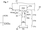
- the mold pin 30 has an upper mold section 31a, a lower mold section 31b and a foot mold section 31c, as shown in Fig. 6 and 7 shown. Furthermore, a fixing section 31d is provided, via which the respective mold pin 30 is received, for example screwed or pressed, in a receiving opening 21b, for example in a threaded hole or a conical hole, in the respective vulcanization segment 21.
- the mold pin 30 is received in the receiving opening 21b in such a way that the upper mold section 31a, the lower mold section 31b, and the foot mold section 31c protrude perpendicularly from the respective vulcanization segment 21, so that a correspondingly vertically extending spike hole 3 can be formed in the tread 1a, in which the contour of the mold pin 30 is depicted.
- the fixing section 31d of the mold pin 30 also protrudes slightly from the respective vulcanization segment 21, so that a step 7 is additionally formed in the tread 1a around the spike hole 3, as shown in the Figures 2 to 5
- the spike hole 3 formed by such a shaped pin 30 is generally approximately 1 mm shorter than the spike 2 to be pressed in, the length of which can be, for example, between 7 mm and 14 mm depending on the application.
- the mold pin 30 is composed of the individual sections 31a, 31b, 31c, 31d in such a way that the fixing section 31d is connected in the longitudinal direction X (with respect to the mold pin 30) to the upper mold section 31a and subsequently the lower mold section 31b and the foot mold section 31c.
- the individual sections 31a, 31b, 31c, 31d are preferably designed as one piece.
- the fixing section 31d starting from its surface 32, merges into the upper mold section 31a via a conical shoulder 33 in a frustoconical shape.
- the upper mold section 31a has an upper mold diameter Da of preferably between 1.5 mm and 4 mm, which is smaller than a lower mold diameter Db of the lower mold section 31b of preferably between 1.5 mm and 7 mm and a foot diameter Dc of the foot mold section 31c of preferably between 6 mm and 11 mm.
- the upper mold section 31a can have a cylindrical shape with a constant upper mold diameter Da (see Fig. 6 ) or a conical shape with an upper mold diameter Da increasing towards the lower mold section 31b (see Fig.
- the lower shape diameter Db is in turn smaller than the base diameter Dc, whereby the lower shape diameter Db is as in Fig. 6 and 7 shown is constant.
- lamellae 34 protrude, preferably perpendicularly, from the surface 32 of the fixing section 31d in the direction of the upper mold section 31a. These lamellae 34 are connected to the frustoconical shoulder 33 and, above all, to the upper mold section 31a of the mold pin 30, so that the mold pin 30 is supported in the transverse direction Q or in the radial direction R (relative to the mold pin 30).
- the slats 34 protrude approximately perpendicularly from a wall 35 of the upper mold section 31a, particularly on opposite sides.
- a slat height H in the longitudinal direction X (relative to the mold pin 30) of the respective slat 34 decreases progressively outward from the wall 35 of the upper mold section 31a in the transverse direction Q or in the radial direction R (relative to the mold pin 30).
- a maximum slat height Hmax, which exists at the contact point of the wall 35, is, for example, between 2 mm and 3 mm.
- a free edge 34a of the respective lamella 34 which runs between the surface 32 of the fixing section 31d and the wall 35 of the upper mold section 31a, has a linear course (see Fig. 6 ) or a rounded gradient (see Fig. 7 ), so that slats 34 with a substantially triangular shape are formed.
- Such shaped lamellae 34 improve the transverse stability of the mold pin 30 during demolding. This allows very narrow or slender upper mold diameters Da to be selected with wider lower mold diameters Db, so that a spike 2 with a very narrow or slender upper section 6a and a wider lower section 6b can be securely pressed or held in the thus formed spike hole 3.
- the sipes 34 are also depicted in the vulcanized tread 1a of the pneumatic vehicle tire 1, as shown schematically in Fig. 2 shown, so that adjacent to the respective spike hole 3, lamellar depressions 36 or notches are formed therein, which have the same shape as the respective lamella 34, i.e. triangular with a linear or rounded shape or the like. Accordingly, depressions 36 are formed radially adjacent to an upper end region 3a of the spike hole 3, starting from a surface 1b of the tread 1a, against which the surfaces 21a of the vulcanization segments 21 and the surface 32 of the fixing section 31d rest.
- the recesses 36 in the upper end region 3a are also connected to the spike hole 3.
- the recesses 36 have a maximum depth Tmax from the surface 1b of the tread 1a, which approximately corresponds to the maximum sipe height Hmax of the sipe 34. Based on this, a depth T of the recess 36 becomes increasingly smaller with increasing distance from the spike hole 3, corresponding to the shape of the free edge 34a or the profile of the sipe height H of the respective sipe 34.
- the flexibility of the spike 2 in the spike hole 3 can also be adjusted, since the spike 2, with its uncovered upper section 6a, rests directly against the tread 1a in the upper end region 3a of the spike hole 3.
- the formed slat-like depressions 36 which are located in particular adjacent to the upper end region 3a of the spike hole 3, then also have an influence on the movement behavior of the pressed-in spike 2 in its upper section 6a.
- the influence on the lower section 6b and the base section 6c, on the other hand, is rather marginal, since the slats 34 only run in the upper shaped section 31a of the shaped pin 30 and the depressions 36 only run in the upper end region 3a of the spike hole 3.
Landscapes
- Engineering & Computer Science (AREA)
- Mechanical Engineering (AREA)
- Tires In General (AREA)
Applications Claiming Priority (1)
| Application Number | Priority Date | Filing Date | Title |
|---|---|---|---|
| DE102023212196.4A DE102023212196A1 (de) | 2023-12-04 | 2023-12-04 | Fahrzeugluftreifen |
Publications (1)
| Publication Number | Publication Date |
|---|---|
| EP4566844A1 true EP4566844A1 (fr) | 2025-06-11 |
Family
ID=93520964
Family Applications (1)
| Application Number | Title | Priority Date | Filing Date |
|---|---|---|---|
| EP24212268.7A Pending EP4566844A1 (fr) | 2023-12-04 | 2024-11-12 | Bandage pneumatique pour véhicule |
Country Status (2)
| Country | Link |
|---|---|
| EP (1) | EP4566844A1 (fr) |
| DE (1) | DE102023212196A1 (fr) |
Citations (12)
| Publication number | Priority date | Publication date | Assignee | Title |
|---|---|---|---|---|
| US3473591A (en) * | 1966-07-04 | 1969-10-21 | Hard Metals Ltd | Anti-skid devices |
| JPS50130003U (fr) * | 1974-04-11 | 1975-10-25 | ||
| JPS55102604U (fr) * | 1979-01-13 | 1980-07-17 | ||
| RU2292269C2 (ru) | 2002-01-10 | 2007-01-27 | Нокиан Ренкаат Ойй | Шип противоскольжения с металлокерамическим элементом |
| US8215354B2 (en) | 2009-10-20 | 2012-07-10 | The Goodyear Tire & Rubber Company | Studs for a tire |
| EP2255959B1 (fr) | 2009-05-27 | 2014-06-25 | Continental Reifen Deutschland GmbH | Procédé d'ancrage de crampons dans la bande de roulement d'un pneu pour véhicule |
| EP2719523B1 (fr) | 2012-10-11 | 2016-03-02 | Sumitomo Rubber Industries, Ltd. | Broche pour moule, moule de pneu et procédé de fabrication de pneus |
| EP2641754B1 (fr) | 2012-03-22 | 2017-04-19 | The Yokohama Rubber Co., Ltd. | Luftreifen |
| DE102017215858A1 (de) * | 2017-09-08 | 2019-03-14 | Continental Reifen Deutschland Gmbh | Verfahren zum Herstellen von Spikes und Fahrzeugluftreifen mit solchen Spikes |
| US10232672B2 (en) | 2015-05-26 | 2019-03-19 | Sumitomo Rubber Industries, Ltd. | Winter tire |
| JP6690927B2 (ja) | 2015-12-11 | 2020-04-28 | Toyo Tire株式会社 | モールドピン及び空気入りタイヤ |
| EP3543039B1 (fr) | 2015-11-23 | 2022-01-19 | Continental Reifen Deutschland GmbH | Pneu de véhicule |
-
2023
- 2023-12-04 DE DE102023212196.4A patent/DE102023212196A1/de active Pending
-
2024
- 2024-11-12 EP EP24212268.7A patent/EP4566844A1/fr active Pending
Patent Citations (13)
| Publication number | Priority date | Publication date | Assignee | Title |
|---|---|---|---|---|
| US3473591A (en) * | 1966-07-04 | 1969-10-21 | Hard Metals Ltd | Anti-skid devices |
| JPS50130003U (fr) * | 1974-04-11 | 1975-10-25 | ||
| JPS55102604U (fr) * | 1979-01-13 | 1980-07-17 | ||
| RU2292269C2 (ru) | 2002-01-10 | 2007-01-27 | Нокиан Ренкаат Ойй | Шип противоскольжения с металлокерамическим элементом |
| EP2777923A1 (fr) | 2009-05-27 | 2014-09-17 | Continental Reifen Deutschland GmbH | Procédé et dispositif destinés au revêtement de crampons |
| EP2255959B1 (fr) | 2009-05-27 | 2014-06-25 | Continental Reifen Deutschland GmbH | Procédé d'ancrage de crampons dans la bande de roulement d'un pneu pour véhicule |
| US8215354B2 (en) | 2009-10-20 | 2012-07-10 | The Goodyear Tire & Rubber Company | Studs for a tire |
| EP2641754B1 (fr) | 2012-03-22 | 2017-04-19 | The Yokohama Rubber Co., Ltd. | Luftreifen |
| EP2719523B1 (fr) | 2012-10-11 | 2016-03-02 | Sumitomo Rubber Industries, Ltd. | Broche pour moule, moule de pneu et procédé de fabrication de pneus |
| US10232672B2 (en) | 2015-05-26 | 2019-03-19 | Sumitomo Rubber Industries, Ltd. | Winter tire |
| EP3543039B1 (fr) | 2015-11-23 | 2022-01-19 | Continental Reifen Deutschland GmbH | Pneu de véhicule |
| JP6690927B2 (ja) | 2015-12-11 | 2020-04-28 | Toyo Tire株式会社 | モールドピン及び空気入りタイヤ |
| DE102017215858A1 (de) * | 2017-09-08 | 2019-03-14 | Continental Reifen Deutschland Gmbh | Verfahren zum Herstellen von Spikes und Fahrzeugluftreifen mit solchen Spikes |
Also Published As
| Publication number | Publication date |
|---|---|
| DE102023212196A1 (de) | 2025-06-05 |
Similar Documents
| Publication | Publication Date | Title |
|---|---|---|
| DE69927666T2 (de) | Reifen mit opferbrücken | |
| EP0758039B1 (fr) | Rail d'ancrage pour la technique du bâtiment | |
| EP2501562B1 (fr) | Sculpture de bande de roulement d'un pneumatique de véhicule | |
| DE69006520T2 (de) | Getriebe mit einem Antriebsriemen und Kegelscheiben. | |
| EP0675011B1 (fr) | Bandage pneumatique avec blocs éjecteurs de pierres | |
| EP1010901A1 (fr) | Douille métallique | |
| EP3401454A1 (fr) | Rail de fixation et composant béton comprenant un rail de fixation | |
| EP2864137B1 (fr) | Bande de roulement de pneumatique | |
| DE60213445T2 (de) | Reifenlauffläche | |
| EP3463837A1 (fr) | Unité de ventilation pour un moule de vulcanisation d'un pneumatique de véhicule | |
| EP4566844A1 (fr) | Bandage pneumatique pour véhicule | |
| DE102019206654A1 (de) | Fahrzeugluftreifen | |
| EP2138327A1 (fr) | Bande de roulement por pneumatique | |
| EP4566803A1 (fr) | Tige de moulage, dispositif de vulcanisation et pneumatique de véhicule | |
| EP3560735B1 (fr) | Pneu de véhicule utilitaire | |
| EP2138328B1 (fr) | Pneus de véhicule | |
| EP1992505B1 (fr) | Pneus de véhicule | |
| EP3815929B1 (fr) | Pneumatique de véhicule et des clous | |
| EP3890994B1 (fr) | Profil de bande de roulement d'un pneu de véhicule | |
| DE69509298T2 (de) | Fahrzeugluftreifen | |
| DE69500821T2 (de) | Blindnietanordnung | |
| EP3789214A1 (fr) | Pneumatique de véhicule | |
| EP2467269B1 (fr) | Pneumatique pour véhicule | |
| DE102020205836A1 (de) | Fahrzeugluftreifen | |
| EP4474172A1 (fr) | Combinaison d'un pneu de véhicule et de clous et pneu de véhicule |
Legal Events
| Date | Code | Title | Description |
|---|---|---|---|
| PUAI | Public reference made under article 153(3) epc to a published international application that has entered the european phase |
Free format text: ORIGINAL CODE: 0009012 |
|
| STAA | Information on the status of an ep patent application or granted ep patent |
Free format text: STATUS: THE APPLICATION HAS BEEN PUBLISHED |
|
| AK | Designated contracting states |
Kind code of ref document: A1 Designated state(s): AL AT BE BG CH CY CZ DE DK EE ES FI FR GB GR HR HU IE IS IT LI LT LU LV MC ME MK MT NL NO PL PT RO RS SE SI SK SM TR |
|
| STAA | Information on the status of an ep patent application or granted ep patent |
Free format text: STATUS: REQUEST FOR EXAMINATION WAS MADE |
|
| 17P | Request for examination filed |
Effective date: 20251211 |