EP4566863A1 - Véhicule de travail électrique - Google Patents
Véhicule de travail électrique Download PDFInfo
- Publication number
- EP4566863A1 EP4566863A1 EP23849672.3A EP23849672A EP4566863A1 EP 4566863 A1 EP4566863 A1 EP 4566863A1 EP 23849672 A EP23849672 A EP 23849672A EP 4566863 A1 EP4566863 A1 EP 4566863A1
- Authority
- EP
- European Patent Office
- Prior art keywords
- state
- storage device
- power storage
- power
- timing
- Prior art date
- Legal status (The legal status is an assumption and is not a legal conclusion. Google has not performed a legal analysis and makes no representation as to the accuracy of the status listed.)
- Pending
Links
Images


Classifications
-
- B—PERFORMING OPERATIONS; TRANSPORTING
- B60—VEHICLES IN GENERAL
- B60L—PROPULSION OF ELECTRICALLY-PROPELLED VEHICLES; SUPPLYING ELECTRIC POWER FOR AUXILIARY EQUIPMENT OF ELECTRICALLY-PROPELLED VEHICLES; ELECTRODYNAMIC BRAKE SYSTEMS FOR VEHICLES IN GENERAL; MAGNETIC SUSPENSION OR LEVITATION FOR VEHICLES; MONITORING OPERATING VARIABLES OF ELECTRICALLY-PROPELLED VEHICLES; ELECTRIC SAFETY DEVICES FOR ELECTRICALLY-PROPELLED VEHICLES
- B60L1/00—Supplying electric power to auxiliary equipment of vehicles
-
- B—PERFORMING OPERATIONS; TRANSPORTING
- B60—VEHICLES IN GENERAL
- B60L—PROPULSION OF ELECTRICALLY-PROPELLED VEHICLES; SUPPLYING ELECTRIC POWER FOR AUXILIARY EQUIPMENT OF ELECTRICALLY-PROPELLED VEHICLES; ELECTRODYNAMIC BRAKE SYSTEMS FOR VEHICLES IN GENERAL; MAGNETIC SUSPENSION OR LEVITATION FOR VEHICLES; MONITORING OPERATING VARIABLES OF ELECTRICALLY-PROPELLED VEHICLES; ELECTRIC SAFETY DEVICES FOR ELECTRICALLY-PROPELLED VEHICLES
- B60L15/00—Methods, circuits, or devices for controlling the traction-motor speed of electrically-propelled vehicles
- B60L15/007—Physical arrangements or structures of drive train converters specially adapted for the propulsion motors of electric vehicles
-
- B—PERFORMING OPERATIONS; TRANSPORTING
- B60—VEHICLES IN GENERAL
- B60L—PROPULSION OF ELECTRICALLY-PROPELLED VEHICLES; SUPPLYING ELECTRIC POWER FOR AUXILIARY EQUIPMENT OF ELECTRICALLY-PROPELLED VEHICLES; ELECTRODYNAMIC BRAKE SYSTEMS FOR VEHICLES IN GENERAL; MAGNETIC SUSPENSION OR LEVITATION FOR VEHICLES; MONITORING OPERATING VARIABLES OF ELECTRICALLY-PROPELLED VEHICLES; ELECTRIC SAFETY DEVICES FOR ELECTRICALLY-PROPELLED VEHICLES
- B60L15/00—Methods, circuits, or devices for controlling the traction-motor speed of electrically-propelled vehicles
- B60L15/20—Methods, circuits, or devices for controlling the traction-motor speed of electrically-propelled vehicles for control of the vehicle or its driving motor to achieve a desired performance, e.g. speed, torque, programmed variation of speed
-
- B—PERFORMING OPERATIONS; TRANSPORTING
- B60—VEHICLES IN GENERAL
- B60L—PROPULSION OF ELECTRICALLY-PROPELLED VEHICLES; SUPPLYING ELECTRIC POWER FOR AUXILIARY EQUIPMENT OF ELECTRICALLY-PROPELLED VEHICLES; ELECTRODYNAMIC BRAKE SYSTEMS FOR VEHICLES IN GENERAL; MAGNETIC SUSPENSION OR LEVITATION FOR VEHICLES; MONITORING OPERATING VARIABLES OF ELECTRICALLY-PROPELLED VEHICLES; ELECTRIC SAFETY DEVICES FOR ELECTRICALLY-PROPELLED VEHICLES
- B60L3/00—Electric devices on electrically-propelled vehicles for safety purposes; Monitoring operating variables, e.g. speed, deceleration or energy consumption
-
- B—PERFORMING OPERATIONS; TRANSPORTING
- B60—VEHICLES IN GENERAL
- B60L—PROPULSION OF ELECTRICALLY-PROPELLED VEHICLES; SUPPLYING ELECTRIC POWER FOR AUXILIARY EQUIPMENT OF ELECTRICALLY-PROPELLED VEHICLES; ELECTRODYNAMIC BRAKE SYSTEMS FOR VEHICLES IN GENERAL; MAGNETIC SUSPENSION OR LEVITATION FOR VEHICLES; MONITORING OPERATING VARIABLES OF ELECTRICALLY-PROPELLED VEHICLES; ELECTRIC SAFETY DEVICES FOR ELECTRICALLY-PROPELLED VEHICLES
- B60L3/00—Electric devices on electrically-propelled vehicles for safety purposes; Monitoring operating variables, e.g. speed, deceleration or energy consumption
- B60L3/12—Recording operating variables ; Monitoring of operating variables
-
- B—PERFORMING OPERATIONS; TRANSPORTING
- B60—VEHICLES IN GENERAL
- B60L—PROPULSION OF ELECTRICALLY-PROPELLED VEHICLES; SUPPLYING ELECTRIC POWER FOR AUXILIARY EQUIPMENT OF ELECTRICALLY-PROPELLED VEHICLES; ELECTRODYNAMIC BRAKE SYSTEMS FOR VEHICLES IN GENERAL; MAGNETIC SUSPENSION OR LEVITATION FOR VEHICLES; MONITORING OPERATING VARIABLES OF ELECTRICALLY-PROPELLED VEHICLES; ELECTRIC SAFETY DEVICES FOR ELECTRICALLY-PROPELLED VEHICLES
- B60L50/00—Electric propulsion with power supplied within the vehicle
- B60L50/50—Electric propulsion with power supplied within the vehicle using propulsion power supplied by batteries or fuel cells
- B60L50/60—Electric propulsion with power supplied within the vehicle using propulsion power supplied by batteries or fuel cells using power supplied by batteries
-
- B—PERFORMING OPERATIONS; TRANSPORTING
- B60—VEHICLES IN GENERAL
- B60L—PROPULSION OF ELECTRICALLY-PROPELLED VEHICLES; SUPPLYING ELECTRIC POWER FOR AUXILIARY EQUIPMENT OF ELECTRICALLY-PROPELLED VEHICLES; ELECTRODYNAMIC BRAKE SYSTEMS FOR VEHICLES IN GENERAL; MAGNETIC SUSPENSION OR LEVITATION FOR VEHICLES; MONITORING OPERATING VARIABLES OF ELECTRICALLY-PROPELLED VEHICLES; ELECTRIC SAFETY DEVICES FOR ELECTRICALLY-PROPELLED VEHICLES
- B60L58/00—Methods or circuit arrangements for monitoring or controlling batteries or fuel cells, specially adapted for electric vehicles
- B60L58/10—Methods or circuit arrangements for monitoring or controlling batteries or fuel cells, specially adapted for electric vehicles for monitoring or controlling batteries
-
- B—PERFORMING OPERATIONS; TRANSPORTING
- B60—VEHICLES IN GENERAL
- B60L—PROPULSION OF ELECTRICALLY-PROPELLED VEHICLES; SUPPLYING ELECTRIC POWER FOR AUXILIARY EQUIPMENT OF ELECTRICALLY-PROPELLED VEHICLES; ELECTRODYNAMIC BRAKE SYSTEMS FOR VEHICLES IN GENERAL; MAGNETIC SUSPENSION OR LEVITATION FOR VEHICLES; MONITORING OPERATING VARIABLES OF ELECTRICALLY-PROPELLED VEHICLES; ELECTRIC SAFETY DEVICES FOR ELECTRICALLY-PROPELLED VEHICLES
- B60L58/00—Methods or circuit arrangements for monitoring or controlling batteries or fuel cells, specially adapted for electric vehicles
- B60L58/10—Methods or circuit arrangements for monitoring or controlling batteries or fuel cells, specially adapted for electric vehicles for monitoring or controlling batteries
- B60L58/18—Methods or circuit arrangements for monitoring or controlling batteries or fuel cells, specially adapted for electric vehicles for monitoring or controlling batteries of two or more battery modules
- B60L58/20—Methods or circuit arrangements for monitoring or controlling batteries or fuel cells, specially adapted for electric vehicles for monitoring or controlling batteries of two or more battery modules having different nominal voltages
-
- B—PERFORMING OPERATIONS; TRANSPORTING
- B62—LAND VEHICLES FOR TRAVELLING OTHERWISE THAN ON RAILS
- B62D—MOTOR VEHICLES; TRAILERS
- B62D49/00—Tractors
- B62D49/06—Tractors adapted for multi-purpose use
- B62D49/0664—Light, simple, and economical tractors
- B62D49/0671—Light, simple, and economical tractors the driver riding on the tractor
-
- G—PHYSICS
- G07—CHECKING-DEVICES
- G07C—TIME OR ATTENDANCE REGISTERS; REGISTERING OR INDICATING THE WORKING OF MACHINES; GENERATING RANDOM NUMBERS; VOTING OR LOTTERY APPARATUS; ARRANGEMENTS, SYSTEMS OR APPARATUS FOR CHECKING NOT PROVIDED FOR ELSEWHERE
- G07C5/00—Registering or indicating the working of vehicles
- G07C5/08—Registering or indicating performance data other than driving, working, idle, or waiting time, with or without registering driving, working, idle or waiting time
- G07C5/0841—Registering performance data
-
- H—ELECTRICITY
- H04—ELECTRIC COMMUNICATION TECHNIQUE
- H04Q—SELECTING
- H04Q9/00—Arrangements in telecontrol or telemetry systems for selectively calling a substation from a main station, in which substation desired apparatus is selected for applying a control signal thereto or for obtaining measured values therefrom
-
- B—PERFORMING OPERATIONS; TRANSPORTING
- B60—VEHICLES IN GENERAL
- B60L—PROPULSION OF ELECTRICALLY-PROPELLED VEHICLES; SUPPLYING ELECTRIC POWER FOR AUXILIARY EQUIPMENT OF ELECTRICALLY-PROPELLED VEHICLES; ELECTRODYNAMIC BRAKE SYSTEMS FOR VEHICLES IN GENERAL; MAGNETIC SUSPENSION OR LEVITATION FOR VEHICLES; MONITORING OPERATING VARIABLES OF ELECTRICALLY-PROPELLED VEHICLES; ELECTRIC SAFETY DEVICES FOR ELECTRICALLY-PROPELLED VEHICLES
- B60L2200/00—Type of vehicles
- B60L2200/40—Working vehicles
-
- B—PERFORMING OPERATIONS; TRANSPORTING
- B60—VEHICLES IN GENERAL
- B60L—PROPULSION OF ELECTRICALLY-PROPELLED VEHICLES; SUPPLYING ELECTRIC POWER FOR AUXILIARY EQUIPMENT OF ELECTRICALLY-PROPELLED VEHICLES; ELECTRODYNAMIC BRAKE SYSTEMS FOR VEHICLES IN GENERAL; MAGNETIC SUSPENSION OR LEVITATION FOR VEHICLES; MONITORING OPERATING VARIABLES OF ELECTRICALLY-PROPELLED VEHICLES; ELECTRIC SAFETY DEVICES FOR ELECTRICALLY-PROPELLED VEHICLES
- B60L2220/00—Electrical machine types; Structures or applications thereof
- B60L2220/40—Electrical machine applications
- B60L2220/42—Electrical machine applications with use of more than one motor
-
- G—PHYSICS
- G07—CHECKING-DEVICES
- G07C—TIME OR ATTENDANCE REGISTERS; REGISTERING OR INDICATING THE WORKING OF MACHINES; GENERATING RANDOM NUMBERS; VOTING OR LOTTERY APPARATUS; ARRANGEMENTS, SYSTEMS OR APPARATUS FOR CHECKING NOT PROVIDED FOR ELSEWHERE
- G07C5/00—Registering or indicating the working of vehicles
- G07C5/008—Registering or indicating the working of vehicles communicating information to a remotely located station
Definitions
- the present invention relates to an electric work vehicle.
- a work vehicle disclosed in JP 2014-042508A is provided with a data collector (“access point device for the work vehicle" in this document) that collects information regarding works.
- Patent Document 1 JP 2014-042508A
- the data collector executes processing for deactivating the communication function. With this, the power consumption by the communication function is reduced when the main power supply of the work vehicle is stopped.
- the present invention aims to realize efficient running of a data collector in an electric work vehicle.
- An electric work vehicle relates to an electric work vehicle including:
- the data collector consumes at least either the power stored in the first power storage device or the power stored in the second power storage device. Therefore, even when the first power storage device has been switched to the second state, the data collector can continuously acquire data by consuming the power stored in the second power storage device.
- the relay device is interposed between the data collector and the second power storage device. The relay device continues to be in the current-flow state until the timing at which the first time elapses even after the first power storage device has been switched to the second state. Therefore, when a driver performs a turn-off operation to terminate the running of the electric work vehicle, the data collector can reliably acquire data at the end of the running.
- the state of the relay device switches from the current-flow state to the blocked state at the timing at which the first time elapses. Accordingly, a current flowing between the data collector and the second power storage device is blocked, and the power supply of the data collector is directly turned off. This avoids the risk that the power stored in the second power storage device will continue to be consumed uselessly by the data collector after the electric work vehicle has stopped running. As a result, efficient running of the data collector is realized in the electric work vehicle.
- the data collector includes a transmitter capable of transmitting the data outside, and the transmitter transmits the data outside during a period from the timing at which the turn-off operation is performed on the switch operation tool to a timing at which the first time elapses.
- the data collector can acquire data without leaving any data behind and transmit the acquired data outside by the timing at which the first time elapses.
- This allows, for example, an external management computer to acquire data until the end of running of the electric work vehicle without delay and use it for failure sign analysis, diagnosis, and the like, for example.
- the electric work vehicle further includes
- the controller since the controller outputs the control signal to the relay device, the relay device is accurately switched from the current-flow state to the blocked state based on the control signal.
- the first power storage device switches from the first state to the second state at a timing at which second time elapses from the timing at which the turn-off operation is performed on the switch operation tool, the second time being shorter than the first time.
- the first power storage device is not immediately switched from the first state to the second state but switches from the first state to the second state at the timing at which the second time elapses. Therefore, at the deactivation of the running of the electric work vehicle, instruments such as the motor can execute preparation processing for terminating the running.
- the second power storage device has an output voltage lower than an output voltage of the first power storage device
- the second power storage device can be charged with the power from the first power storage device. This avoids the risk that the power of the second power storage device becomes insufficient, and the data collector can reliably acquire data at the end of the running of the electric work vehicle.
- the voltage converter blocks a current flowing between the first power storage device and the second power storage device in response to the state of the first power storage device being switched from the first state to the second state.
- the power stored in the first power storage device is no longer consumed by the second power storage device during the second state.
- the running of the first power storage device is reliably deactivated after the deactivation of the running of the electric work vehicle.
- the electric work vehicle further includes
- the motor and the first power storage device tend to generate heat in response to the running of the electric work vehicle.
- the data collector is provided behind the seat and is located apart from the motor and the first power storage device, which are provided in front of the seat. With this, the data collector is less susceptible to the heat generated by the motor and the first power storage device.
- FIG. 1 shows an electric tractor as an example of an electric work vehicle.
- the electric tractor includes left and right front wheels 10, left and right rear wheels 11, and a cover member 12.
- the electric tractor also includes a body frame 2 and a driving section 3.
- the body frame 2 is supported by the left and right front wheels 10 and the left and right rear wheels 11.
- the cover member 12 is disposed in a front portion of the body of the electric tractor.
- the driving section 3 is provided behind the cover member 12. In other words, the cover member 12 is provided in front of the driving section 3.
- the driving section 3 includes a protective frame 30, a seat 31, and a steering wheel 32.
- a driver can sit on the seat 31. Accordingly, the driver can get on the driving section 3.
- the left and right front wheels 10 are used to change the orientation thereof through the operation of the steering wheel 32.
- the driver can perform various driving operations in the driving section 3.
- the electric tractor includes a travel battery unit 4. Also, the cover member 12 is pivotable about an opening/closing axis Q extending in the left-right direction of the body. Accordingly, the cover member 12 is openable and closeable. When the cover member 12 is closed, the travel battery unit 4 is covered by the cover member 12.
- the travel battery unit 4 corresponds to the "first power storage device" of the present invention.
- the electric tractor includes an inverter 14 and a motor M.
- the travel battery unit 4 supplies power to the inverter 14.
- the inverter 14 converts DC power supplied from the travel battery unit 4 into AC power, and supplies the AC power to the motor M.
- the motor M is driven by the AC power supplied from the inverter 14. In other words, the motor M is driven by consuming the power stored in the travel battery unit 4.
- the electric tractor includes a hydraulic static transmission 15 and a transmission 16.
- the hydraulic static transmission 15 includes a hydraulic pump 15a and a hydraulic motor 15b.
- the hydraulic pump 15a is driven by rotational motive power transmitted from the motor M. As a result of the hydraulic pump 15a being driven, rotational motive power is output from the hydraulic motor 15b.
- the hydraulic static transmission 15 is configured to change the speed of the rotational motive power between the hydraulic pump 15a and the hydraulic motor 15b. Also, the hydraulic static transmission 15 is able to change the transmission ratio in a stepless manner.
- the rotational motive power output from the hydraulic motor 15b is transmitted to the transmission 16.
- the rotational motive power transmitted to the transmission 16 is subjected to speed change by a gear transmission mechanism included in the transmission 16, and is distributed to the left and right front wheels 10 and the left and right rear wheels 11.
- the left and right front wheels 10 and the left and right rear wheels 11 are driven.
- the electric tractor also includes a middle PTO shaft 17 and a rear PTO shaft 18.
- the rotational motive power output from the motor M is distributed to the hydraulic pump 15a, the middle PTO shaft 17, and the rear PTO shaft 18. With this, the middle PTO shaft 17 and the rear PTO shaft 18 are rotated.
- a work device is connected to the middle PTO shaft 17 or the rear PTO shaft 18, the work device is driven by the rotational motive power transmitted by the middle PTO shaft 17 or the rear PTO shaft 18.
- a mowing device 19 is connected to the middle PTO shaft 17. The mowing device 19 is driven by the rotational motive power transmitted by the middle PTO shaft 17.
- the mowing device 19 corresponds to the "work device” of the present invention.
- the left and right front wheels 10 and the left and right rear wheels 11 correspond to the "travel device” of the present invention.
- the motor M drives the mowing device 19, the left and right front wheels 10, and the left and right rear wheels 11.
- a telematics device 38 is provided behind the seat 31.
- the telematics device 38 collects data regarding detected values of the electrical components of the electric tractor and detected values of sensors, and transfers the collected data to an external management computer 5 (see FIG. 4 ).
- the telematics device 38 corresponds to the "data collector" of the present invention.
- the telematics device 38 will be described in detail later.
- the motor M and the travel battery unit 4 are provided in front of the seat 31, and the telematics device 38 is provided behind the seat 31.
- the control configuration of the motor M includes an accelerator device 33, a controller 34 that controls the driving of the motor M, and the inverter 14.
- the controller 34 is the core element of the control system of the electric work vehicle and is configured as a collection of a plurality of ECUs.
- the accelerator device 33 is provided near the steering wheel 32. Although not shown in the figure, the accelerator device 33 includes a lever that can be pivoted and operated, and a potentiometer that detects the amount of pivoting operation of the lever.
- the accelerator device 33 is connected to the controller 34.
- the controller 34 is connected to the inverter 14 via a signal harness 35.
- the controller 34 outputs command signals to the inverter 14 in response to commands from the accelerator device 33.
- the inverter 14 controls the output of the motor M by adjusting the power (such as a voltage value, a frequency, and a current value) to be supplied to the motor M from the travel battery unit 4 in response to the command signal from the controller 34.
- the travel battery unit 4 is, for example, a lithium-ion battery. Although not shown in the figure, the travel battery unit 4 is constituted by a number of small low-voltage unit batteries (cells) stacked together. The output voltage of the travel battery unit 4 is, for example, 250 volts.
- the unit batteries (cells) are stored in a storage case. These unit batteries (cells) are sealed by the storage case.
- the travel battery unit 4 also includes a charge/discharge controller 4A.
- the charge/discharge controller 4A has multiple control modes, which will be described in detail later.
- the control modes of the charge/discharge controller 4A include a charge mode, a discharge mode, and a non-operation mode.
- the charge/discharge controller 4A may be, for example, a power module or PLC (programmable logic controller) including a microcomputer that executes a program based on a control signal from the controller 34, or may be a relay circuit that operates based on an electrical signal from the controller 34.
- PLC programmable logic controller
- the electric tractor is provided with, in addition to the travel battery unit 4, a battery 41 for electrical components that supplies power to the controller 34 and other electrical components.
- the battery 41 for electrical components is, for example, a lead-battery.
- the battery 41 for electrical components supplies power of a low voltage (e.g., 12 volts) to drive the electrical components.
- the output voltage of the battery 41 for electrical components is lower than the output voltage of the travel battery unit 4.
- the battery 41 for electrical components corresponds to the "second power storage device" of the present invention.
- the battery 41 for electrical components is charged with power supplied from the travel battery unit 4 via a DC/DC converter 42.
- the DC/DC converter 42 can step down the voltage of the travel battery unit 4 to the voltage of the battery 41 for electrical components, and then supply the resulting power to the electrical components such as the telematics device 38.
- the DC/DC converter 42 can also supply power to the battery 41 for electrical components.
- the DC/DC converter 42 is connected to both the travel battery unit 4 and the battery 41 for electrical components so that a current can flow therebetween, and is capable of receiving power from the travel battery unit 4, stepping down the voltage of the power, and transmitting the resulting power to the battery 41 for electrical components.
- the travel battery unit 4 can supply power to the battery 41 for electrical components and can charge the battery 41 for electrical components.
- the battery 41 for electrical components is chargeable with power received from the travel battery unit 4 via the DC/DC converter 42.
- the DC/DC converter 42 corresponds to the "voltage converter" of the present invention.
- a switch operation tool 44 is provided in the driving section 3.
- the switch operation tool 44 includes an insertion slot 46 into which a portable operation key 45 can be inserted and mounted, and a switch 47 of a push-button type that can be manually pushed.
- the control mode of the charge/discharge controller 4A switches from the non-operation mode to the discharge mode.
- the pushing operation of the switch 47 with the operation key 45 inserted and mounted in the insertion slot 46 is referred to as a "turn-on operation" of the switch operation tool 44.
- the operation key 45 functions as a key that can only be identified by the corresponding work vehicle.
- An operation panel 43 includes a meter panel 48.
- the meter panel 48 displays, for example, the travel status of the vehicle body, the work status, battery information (such as charge amount and temperature), and the like.
- the meter panel 48 is connected to the controller 34, and the controller 34 controls the operation of the meter panel 48.
- the controller 34, the inverter 14, the travel battery unit 4, the DC/DC converter 42, the meter panel 48, the telematics device 38, a relay device 39, and the like are connected to each other via the signal harness 35 of the CAN (Controller Area Network) type so as to be able to perform data communication. Communication is performed between the controller 34 and a charge connection section 37 via a harness 49 for charging communication. Information on whether or not a power supply connector 36 is connected to the charge connection section 37, information on the charging current required on the work vehicle side, and the like are transmitted. Signals can also be communicated between the charge connection section 37 and a power feeder KD. Also, information on the operation of the switch operation tool 44 is input to the controller 34.
- the charge connection section 37 may also be connected to the controller 34 and the like via the signal harness 35 so as to be able to perform data communication.
- the controller 34 transmits a control signal for charging to the charge/discharge controller 4A via the signal harness 35.
- the control mode of the charge/discharge controller 4A is then switched to the charge mode, and the travel battery unit 4 is charged by the power feeder KD. At this time, the travel battery unit 4 is not discharged to the motor M.
- the controller 34 transmits a control signal for charging to the charge/discharge controller 4A via the signal harness 35. Then, the control mode of the charge/discharge controller 4A switches from the non-operation mode to the discharge mode.
- the travel battery unit 4 can be discharged to the motor M. At this time, the travel battery unit 4 is in a first state of supplying power.
- the control mode of the charge/discharge controller 4A is the discharge mode, the DC/DC converter 42 steps down the voltage of the travel battery unit 4 to the voltage of the battery 41 for electrical components, then supplies the resulting power to the electrical components such as the telematics device 38, and charges the battery 41 for electrical components.
- the controller 34 transmits a control signal for stopping charging/discharging to the charge/discharge controller 4A via the signal harness 35. Then, the control mode of the charge/discharge controller 4A is switched to the non-operation mode.
- the operation of removing the operation key 45 from the insertion slot 46 is referred to as a "turn-off operation" of the switch operation tool 44.
- the travel battery unit 4 In response to the control mode of the charge/discharge controller 4A being switched to the non-operation mode, the travel battery unit 4 can no longer be discharged to the motor M. At this time, the travel battery unit 4 is in a second state of not supplying power. At this time, the travel battery unit 4 is not charged by the power feeder KD.
- the control mode of the charge/discharge controller 4A is the non-operation mode, power supply from the DC/DC converter 42 to the electrical components such as the telematics device 38, and the battery 41 for electrical components is also stopped. That is, in response to the state of the travel battery unit 4 being switched from the first state to the second state, the DC/DC converter 42 blocks a current flowing between the travel battery unit 4 and the battery 41 for electrical components.
- the travel battery unit 4 is switchable between the first state of supplying power and the second state of not supplying power.
- the state of the travel battery unit 4 switches from the second state to the first state in response to the switch operation tool 44 being turned on, and the state of the travel battery unit 4 switches from the first state to the second state in response to the switch operation tool 44 being turned off.
- the switch operation tool 44 accepts the turn-on operation of switching the state of the travel battery unit 4 from the second state to the first state, and the turn-off operation of switching the state of the travel battery unit 4 from the first state to the second state.
- the telematics device 38 acquires data including information on the motor M, the inverter 14, the travel battery unit 4, the DC/DC converter 42, and the like via the signal harness 35 over time.
- the information includes, for example, the amount of charge, the amount of discharge, the temperature of generated heat, alarm history, and abnormality history of the travel battery unit 4, and the like.
- the information also includes, for example, the output value of the motor M, the temperature of the motor M, the command value of the inverter 14, the temperatures of the inverter 14 and the DC/DC converter 42, the alarm history and abnormality history in the controller 34, and the like.
- the telematics device 38 includes a transmitter 38A and a receiver 38B.
- the information acquired by the telematics device 38 is transmitted from the transmitter 38A to the external management computer 5 via the wireless Internet network.
- the transmitter 38A executes transmitting processing at intervals of 15 minutes, for example.
- the management computer 5 Based on the information received from the telematics device 38, the management computer 5 performs diagnosis regarding whether or not the tractor has any failure, and estimates the lifetime prediction of the travel battery unit 4, the inverter 14, and the like, for example.
- the receiver 38B is used, for example, to receive a response signal from the management computer 5 and an update program from the management computer 5, via a wireless Internet network.
- the management computer 5 may be, for example, a portable tablet device, a smartphone, or smartwatch.
- the telematics device 38 is also used as a positioning device that receives positioning signals from satellites (not shown) used in the GNSS (Global Satellite Navigation System, e.g., GPS, GLONASS, Galileo, QZSS, BeiDou, etc.).
- GNSS Global Satellite Navigation System
- inertial measurement devices such as a gyro accelerometer sensor and a magnetic direction sensor may be incorporated into the telematics device 38, for example.
- the telematics device 38 is provided behind the seat 31.
- the motor M and the travel battery unit 4 tend to generate heat in response to the running of the electric work vehicle. If the temperature of the telematics device 38 becomes high due to the heat generated by the motor M and the travel battery unit 4, the telematics device 38 may stop running to prevent thermal runaway.
- the telematics device 38 is less susceptible to the heat generated by the motor M and the travel battery unit 4.
- the telematics device 38 is misaligned to any one of left and right sides with respect to the seat 31.
- the telematics device 38 is located at a right-side position of the body with respect to the right side of the seat 31. This reduces the risk that radio wave communications in the transmitter 38A and the receiver 38B is shielded by the seat 31, compared to a configuration in which the telematics device 38 is provided immediately behind the seat 31.
- the telematics device 38 can receive power from the travel battery unit 4 via the DC/DC converter 42.
- the telematics device 38 can also receive power from the battery 41 for electrical components. That is to say, the telematics device 38 can receive power from both the travel battery unit 4 and the battery 41 for electrical components. If the control mode of the charge/discharge controller 4A is switched to the non-operation mode while the transmitter 38A and the receiver 38B of the telematics device 38 are communicating with the management computer 5, the telematics device 38 cannot receive power from the travel battery unit 4. Even in such a case, the telematics device 38 can continue the communication processing in the transmitter 38A and the receiver 38B without interruption, by receiving power from the battery 41 for electrical components.
- the telematics device 38 acquires data including information on the driving of the motor M over time, by consuming at least either the power stored in the travel battery unit 4 or the power stored in the battery 41 for electrical components.
- the relay device 39 is provided at a mid-way position of a wiring connected between the battery 41 for electrical components and the telematics device 38.
- the relay device 39 may be, for example, a power module or PLC (programmable logic controller) including a microcomputer that executes a program based on a control signal from the controller 34, or may be a relay circuit that operates based on an electrical signal from the controller 34.
- the relay device 39 is connected to both the battery 41 for electrical components and the telematics device 38.
- the relay device 39 is switchable between a current-flow state where a current is allowed to flow between the battery 41 for electrical components and the telematics device 38, and a blocked state where a current flowing between the battery 41 for electrical components and the telematics device 38 is blocked, based on a control signal from the controller 34.
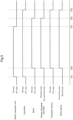
- the behaviors of the devices based on the operation of the switch operation tool 44 is described with reference to FIG. 5 .
- the logic graph diagram shown in FIG. 5 shows the states of the switch operation tool 44, the controller 34, the travel battery unit 4, the motor M, the telematics device 38, and the relay device 39.
- An ON state of the switch operation tool 44 shown in FIG. 5 is a condition in which the switch operation tool 44 is turned on. If this condition is not met, the switch operation tool 44 is in an OFF state.
- the behaviors of the devices when activating the drive device of the tractor will be described.
- the switch operation tool 44 is turned on and the state of the switch operation tool 44 is switched from the OFF state to the ON state.
- the state of the controller 34 is switched from the OFF state to the ON state, and the controller 34 first executes activation processing.
- the activation processing of the controller 34 means, for example, initialization processing of an integrated circuit mounted on the controller 34, and the like.
- the activation processing of the controller 34 is complete.
- the controller 34 outputs a control signal for discharging to the charge/discharge controller 4A.
- the control mode of the charge/discharge controller 4A of the travel battery unit 4 is switched from the non-operation mode to the discharge mode.
- the controller 34 outputs a control signal for charging to the charge/discharge controller 4A, and the control mode of the charge/discharge controller 4A is switched from the non-operation mode to the charge mode.
- the motor M In response to the control mode of the charge/discharge controller 4A being switched from the non-operation mode to the discharge mode, the motor M is also switched from the OFF state to the ON state, so the motor M is able to be driven. Note that when the control mode of the charge/discharge controller 4A is switched from the non-operation mode to the charge mode, the motor M is maintained in the OFF state.
- the telematics device 38 can receive power from the travel battery unit 4, and the state of the telematics device 38 is switched from the OFF state to the ON state.
- the ON state of the telematics device 38 shown in FIG. 5 is a state where the telematics device 38 is operating.
- the OFF state of the telematics device 38 shown in FIG. 5 is a state where the telematics device 38 is not supplied with power.
- the controller 34 Upon completion of the activation processing of the controller 34, the controller 34 also outputs a control signal to the relay device 39, and the relay device 39 is switched from the blocked state to the current-flow state.
- the telematics device 38 can receive power from the battery 41 for electrical components. Therefore, even if the control mode of the charge/discharge controller 4A is switched to the non-operation mode and the telematics device 38 cannot receive power from the travel battery unit 4, the telematics device 38 can continue to operate with power from the battery 41 for electrical components.
- the state of the controller 34 is switched from the OFF state to the ON state at the same time as the state of the switch operation tool 44 is switched from the OFF state to the ON state. Then, at timing TS2, at which preset time has elapsed from timing TS1, at which the states of the switch operation tool 44 and the controller 34 have been switched to the ON state, the activation processing of the controller 34 is complete.
- the control mode of the charge/discharge controller 4A is switched from the non-operation mode to the discharge mode, and the state of the motor M is switched from the OFF state to the ON state.
- the state of the relay device 39 is switched from the blocked state to the current-flow state, and the state of the telematics device 38 is switched from the OFF state to the ON state.
- the controller 34 transmits a control signal for non-operation to the charge/discharge controller 4A via the signal harness 35.
- the controller 34 also outputs a control signal for non-operation to the inverter 14 and the meter panel 48.
- the charge/discharge controller 4A performs processing for stopping the discharge of the travel battery unit 4.
- the inverter 14 also performs discharge processing of the electric charge stored in an internal capacitor, and other processing, for example. In other words, from timing TE1 to timing TE2 shown in FIG. 5 , the charge/discharge controller 4A and the inverter 14 perform deactivation processing for terminating the running.
- timing TE2 shown in FIG. 5 the deactivation processing of the charge/discharge controller 4A and the inverter 14 is complete.
- the control mode of the charge/discharge controller 4A is switched from the discharge mode to the non-operation mode, and the state of the motor M is switched from the ON state to the OFF state.
- Time elapsed from timing TE1 to timing TE2 corresponds to the "second time" of the present invention.
- the travel battery unit 4 is switched from the first state to the second state at timing TE2, at which the second time elapses from timing TE1, at which the switch operation tool 44 is turned off.
- the second time is set to 1 to 10 minutes, for example.
- the telematics device 38 continues to operate based on power from the battery 41 for electrical components. At this time, the telematics device 38 transmits information acquired and stored over time to the external management computer 5 using the transmitter 38A. In other words, the telematics device 38 transmits the stored information to the management computer 5 during the period from timing TE1 to timing TE3.
- Time elapsed from timing TE1 to timing TE3 corresponds to the "first time" of the present invention.
- the relay device 39 is switched from the current-flow state to the blocked state when the preset first time elapses from timing TE1, at which the switch operation tool 44 is turned off.
- the transmitter 38A of the telematics device 38 transmits data outside during the period from timing TE1, at which the switch operation tool 44 is turned off, to timing TE3, at which the first time elapses.
- the first time is set to 5 to 15 minutes, for example. Note that the second time is set to be shorter than the first time.
- the transmitting processing of the telematics device 38 is complete until timing TE3 shown in FIG. 5 elapses.
- the controller 34 outputs a control signal to the relay device 39, and the state of the relay device 39 is switched from the current-flow state to the blocked state.
- the controller 34 outputs a control signal to switch the relay device 39 from the current-flow state to the blocked state at timing TE3, at which the first time elapses from timing TE1, at which the switch operation tool 44 is turned off.
- the state of the telematics device 38 is switched from the ON state to the OFF state in response to interruption of the power from the battery 41 for electrical components.
- the controller 34 executes the deactivation processing and the state of the controller 34 is switched from the ON state to the OFF state.
- the present invention is not limited to the configurations exemplified in the above embodiment, and other representative embodiments of the present invention will be given below.
- the present invention is applicable to an electric work vehicle.
Landscapes
- Engineering & Computer Science (AREA)
- Transportation (AREA)
- Power Engineering (AREA)
- Mechanical Engineering (AREA)
- Sustainable Development (AREA)
- Life Sciences & Earth Sciences (AREA)
- Sustainable Energy (AREA)
- Combustion & Propulsion (AREA)
- Chemical & Material Sciences (AREA)
- Physics & Mathematics (AREA)
- General Physics & Mathematics (AREA)
- Computer Networks & Wireless Communication (AREA)
- Electric Propulsion And Braking For Vehicles (AREA)
- Arrangements For Transmission Of Measured Signals (AREA)
Applications Claiming Priority (2)
| Application Number | Priority Date | Filing Date | Title |
|---|---|---|---|
| JP2022123814A JP7796609B2 (ja) | 2022-08-03 | 2022-08-03 | 電動作業車 |
| PCT/JP2023/001816 WO2024029104A1 (fr) | 2022-08-03 | 2023-01-23 | Véhicule de travail électrique |
Publications (1)
| Publication Number | Publication Date |
|---|---|
| EP4566863A1 true EP4566863A1 (fr) | 2025-06-11 |
Family
ID=89849039
Family Applications (1)
| Application Number | Title | Priority Date | Filing Date |
|---|---|---|---|
| EP23849672.3A Pending EP4566863A1 (fr) | 2022-08-03 | 2023-01-23 | Véhicule de travail électrique |
Country Status (4)
| Country | Link |
|---|---|
| US (1) | US20250170898A1 (fr) |
| EP (1) | EP4566863A1 (fr) |
| JP (1) | JP7796609B2 (fr) |
| WO (1) | WO2024029104A1 (fr) |
Family Cites Families (4)
| Publication number | Priority date | Publication date | Assignee | Title |
|---|---|---|---|---|
| JP5913002B2 (ja) | 2012-08-28 | 2016-04-27 | 株式会社クボタ | 作業機用アクセスポイント装置及び作業機用アクセスポイント装置を備えた作業機の通信システム |
| JP6628616B2 (ja) * | 2016-01-19 | 2020-01-15 | 株式会社クボタ | プラグインハイブリッド作業車 |
| JP6812771B2 (ja) * | 2016-12-09 | 2021-01-13 | 三菱自動車工業株式会社 | 電源制御装置 |
| JP6811698B2 (ja) * | 2017-11-21 | 2021-01-13 | 株式会社クボタ | 作業車及び作業車管理システム |
-
2022
- 2022-08-03 JP JP2022123814A patent/JP7796609B2/ja active Active
-
2023
- 2023-01-23 WO PCT/JP2023/001816 patent/WO2024029104A1/fr not_active Ceased
- 2023-01-23 EP EP23849672.3A patent/EP4566863A1/fr active Pending
-
2025
- 2025-01-30 US US19/041,164 patent/US20250170898A1/en active Pending
Also Published As
| Publication number | Publication date |
|---|---|
| WO2024029104A1 (fr) | 2024-02-08 |
| JP2024021167A (ja) | 2024-02-16 |
| US20250170898A1 (en) | 2025-05-29 |
| JP7796609B2 (ja) | 2026-01-09 |
Similar Documents
| Publication | Publication Date | Title |
|---|---|---|
| US5578915A (en) | Dynamic battery state-of-charge and capacity determination | |
| CN103975499B (zh) | 电池控制系统 | |
| EP4083400A1 (fr) | Machine de travail | |
| US20150298555A1 (en) | Range extender control | |
| GB2498817A (en) | Controlling power consumed from vehicle battery | |
| US11724619B2 (en) | Vehicle | |
| US20250115167A1 (en) | Work vehicle, work vehicle control device, and control method | |
| US20250170898A1 (en) | Electric work vehicle | |
| US20240399927A1 (en) | Electric work vehicle | |
| EP3466742B1 (fr) | Système de gestion, de diagnostic et d'interconnexion de diverses batteries de propulsion d'un véhicule électrique | |
| CN111559456A (zh) | 助力自行车电池的监控系统、助力自行车及远程控制系统 | |
| US20170352925A1 (en) | Battery communication system for battery packs | |
| US20240383362A1 (en) | Electric work vehicle | |
| US20250229645A1 (en) | Electric work vehicle | |
| JP7796612B2 (ja) | 電動作業車、及び、充電方法 | |
| CN112449816B (zh) | 增程器、混合动力插秧机和混合动力插秧机的工作方法 | |
| US20250115130A1 (en) | Working machine | |
| JP2023097970A (ja) | 電動作業車 | |
| JP7507742B2 (ja) | 電動作業車 | |
| EP4417460A1 (fr) | Véhicule de travail électrique | |
| WO2026004545A1 (fr) | Véhicule de travail électrique, et système et procédé de commande de véhicule de travail électrique | |
| WO2026004542A1 (fr) | Système d'entraînement, véhicule de travail, procédé de commande et programme informatique | |
| WO2023127363A1 (fr) | Engin de chantier électrique | |
| WO2026004546A1 (fr) | Véhicule électrique de chantier, et système et procédé de commande de véhicule électrique de chantier | |
| WO2026004282A1 (fr) | Engin électrique de chantier |
Legal Events
| Date | Code | Title | Description |
|---|---|---|---|
| STAA | Information on the status of an ep patent application or granted ep patent |
Free format text: STATUS: THE INTERNATIONAL PUBLICATION HAS BEEN MADE |
|
| PUAI | Public reference made under article 153(3) epc to a published international application that has entered the european phase |
Free format text: ORIGINAL CODE: 0009012 |
|
| STAA | Information on the status of an ep patent application or granted ep patent |
Free format text: STATUS: REQUEST FOR EXAMINATION WAS MADE |
|
| 17P | Request for examination filed |
Effective date: 20250206 |
|
| AK | Designated contracting states |
Kind code of ref document: A1 Designated state(s): AL AT BE BG CH CY CZ DE DK EE ES FI FR GB GR HR HU IE IS IT LI LT LU LV MC ME MK MT NL NO PL PT RO RS SE SI SK SM TR |
|
| DAV | Request for validation of the european patent (deleted) | ||
| DAX | Request for extension of the european patent (deleted) |