EP4566896A1 - Structure de porte à airbag, composant intérieur de véhicule et procédé de fabrication - Google Patents
Structure de porte à airbag, composant intérieur de véhicule et procédé de fabrication Download PDFInfo
- Publication number
- EP4566896A1 EP4566896A1 EP23849505.5A EP23849505A EP4566896A1 EP 4566896 A1 EP4566896 A1 EP 4566896A1 EP 23849505 A EP23849505 A EP 23849505A EP 4566896 A1 EP4566896 A1 EP 4566896A1
- Authority
- EP
- European Patent Office
- Prior art keywords
- mesh fabric
- hinge
- recess
- door cover
- vehicle interior
- Prior art date
- Legal status (The legal status is an assumption and is not a legal conclusion. Google has not performed a legal analysis and makes no representation as to the accuracy of the status listed.)
- Pending
Links
Images


Classifications
-
- B—PERFORMING OPERATIONS; TRANSPORTING
- B60—VEHICLES IN GENERAL
- B60R—VEHICLES, VEHICLE FITTINGS, OR VEHICLE PARTS, NOT OTHERWISE PROVIDED FOR
- B60R21/00—Arrangements or fittings on vehicles for protecting or preventing injuries to occupants or pedestrians in case of accidents or other traffic risks
- B60R21/02—Occupant safety arrangements or fittings, e.g. crash pads
- B60R21/16—Inflatable occupant restraints or confinements designed to inflate upon impact or impending impact, e.g. air bags
- B60R21/20—Arrangements for storing inflatable members in their non-use or deflated condition; Arrangement or mounting of air bag modules or components
- B60R21/21—Arrangements for storing inflatable members in their non-use or deflated condition; Arrangement or mounting of air bag modules or components in vehicle side panels, e.g. doors
-
- B—PERFORMING OPERATIONS; TRANSPORTING
- B60—VEHICLES IN GENERAL
- B60R—VEHICLES, VEHICLE FITTINGS, OR VEHICLE PARTS, NOT OTHERWISE PROVIDED FOR
- B60R21/00—Arrangements or fittings on vehicles for protecting or preventing injuries to occupants or pedestrians in case of accidents or other traffic risks
- B60R21/02—Occupant safety arrangements or fittings, e.g. crash pads
- B60R21/16—Inflatable occupant restraints or confinements designed to inflate upon impact or impending impact, e.g. air bags
- B60R21/20—Arrangements for storing inflatable members in their non-use or deflated condition; Arrangement or mounting of air bag modules or components
- B60R21/205—Arrangements for storing inflatable members in their non-use or deflated condition; Arrangement or mounting of air bag modules or components in dashboards
-
- B—PERFORMING OPERATIONS; TRANSPORTING
- B60—VEHICLES IN GENERAL
- B60R—VEHICLES, VEHICLE FITTINGS, OR VEHICLE PARTS, NOT OTHERWISE PROVIDED FOR
- B60R21/00—Arrangements or fittings on vehicles for protecting or preventing injuries to occupants or pedestrians in case of accidents or other traffic risks
- B60R21/02—Occupant safety arrangements or fittings, e.g. crash pads
- B60R21/16—Inflatable occupant restraints or confinements designed to inflate upon impact or impending impact, e.g. air bags
- B60R21/20—Arrangements for storing inflatable members in their non-use or deflated condition; Arrangement or mounting of air bag modules or components
- B60R21/205—Arrangements for storing inflatable members in their non-use or deflated condition; Arrangement or mounting of air bag modules or components in dashboards
- B60R21/206—Arrangements for storing inflatable members in their non-use or deflated condition; Arrangement or mounting of air bag modules or components in dashboards in the lower part of dashboards, e.g. for protecting the knees
-
- B—PERFORMING OPERATIONS; TRANSPORTING
- B60—VEHICLES IN GENERAL
- B60R—VEHICLES, VEHICLE FITTINGS, OR VEHICLE PARTS, NOT OTHERWISE PROVIDED FOR
- B60R21/00—Arrangements or fittings on vehicles for protecting or preventing injuries to occupants or pedestrians in case of accidents or other traffic risks
- B60R21/02—Occupant safety arrangements or fittings, e.g. crash pads
- B60R21/16—Inflatable occupant restraints or confinements designed to inflate upon impact or impending impact, e.g. air bags
- B60R21/20—Arrangements for storing inflatable members in their non-use or deflated condition; Arrangement or mounting of air bag modules or components
- B60R21/215—Arrangements for storing inflatable members in their non-use or deflated condition; Arrangement or mounting of air bag modules or components characterised by the covers for the inflatable member
-
- B—PERFORMING OPERATIONS; TRANSPORTING
- B60—VEHICLES IN GENERAL
- B60R—VEHICLES, VEHICLE FITTINGS, OR VEHICLE PARTS, NOT OTHERWISE PROVIDED FOR
- B60R21/00—Arrangements or fittings on vehicles for protecting or preventing injuries to occupants or pedestrians in case of accidents or other traffic risks
- B60R21/02—Occupant safety arrangements or fittings, e.g. crash pads
- B60R21/16—Inflatable occupant restraints or confinements designed to inflate upon impact or impending impact, e.g. air bags
- B60R21/20—Arrangements for storing inflatable members in their non-use or deflated condition; Arrangement or mounting of air bag modules or components
- B60R21/215—Arrangements for storing inflatable members in their non-use or deflated condition; Arrangement or mounting of air bag modules or components characterised by the covers for the inflatable member
- B60R2021/21537—Arrangements for storing inflatable members in their non-use or deflated condition; Arrangement or mounting of air bag modules or components characterised by the covers for the inflatable member characterised by hinges
-
- B—PERFORMING OPERATIONS; TRANSPORTING
- B60—VEHICLES IN GENERAL
- B60R—VEHICLES, VEHICLE FITTINGS, OR VEHICLE PARTS, NOT OTHERWISE PROVIDED FOR
- B60R21/00—Arrangements or fittings on vehicles for protecting or preventing injuries to occupants or pedestrians in case of accidents or other traffic risks
- B60R21/02—Occupant safety arrangements or fittings, e.g. crash pads
- B60R21/16—Inflatable occupant restraints or confinements designed to inflate upon impact or impending impact, e.g. air bags
- B60R21/20—Arrangements for storing inflatable members in their non-use or deflated condition; Arrangement or mounting of air bag modules or components
- B60R21/215—Arrangements for storing inflatable members in their non-use or deflated condition; Arrangement or mounting of air bag modules or components characterised by the covers for the inflatable member
- B60R21/216—Arrangements for storing inflatable members in their non-use or deflated condition; Arrangement or mounting of air bag modules or components characterised by the covers for the inflatable member comprising tether means for limitation of cover motion during deployment
- B60R2021/2163—Arrangements for storing inflatable members in their non-use or deflated condition; Arrangement or mounting of air bag modules or components characterised by the covers for the inflatable member comprising tether means for limitation of cover motion during deployment with energy absorbing or elastic means
Definitions
- the invention relates to airbags, and more particularly to an airbag door structure, a vehicle interior component, and a manufacturing method.
- a co-driver airbag on the vehicle is mounted below an instrument panel.
- the airbag is exploded and opened from the instrument panel at the time of a collision and is inflated to protect the co-driver.
- Known airbag door structures typically employ an inserted injection molding structure of a mesh fabric and a framework. Such an airbag door structure has advantages of reduced cost and simple structure with respect to other structures.
- the airbag door structure always has the problems of poor combination of the mesh fabric and the airbag door, cracking or breaking of the mesh fabric pressing rib of the airbag door during explosion, and the failure point of detachment between an airbag door cover and a mesh fabric, which lead to the failure of low-temperature ignition.
- How to better design a better energy-absorbing airbag door structure, especially under demanding conditions, to ensure the integrity of the airbag door cover and increase the safety margin of the ignition experiment becomes an urgent need, which plays a significant role in increasing the safety of passengers.
- the invention provides an airbag door structure, a vehicle interior component, and a manufacturing method, in order to solve the above-mentioned problems of poor combination of a mesh fabric and an airbag door during explosion in the prior art.
- a mesh fabric is connected and fixed on an inner side of a framework facing an airbag;
- the framework comprising a door cover and a side panel which are connected by means of a hinge, wherein the door cover is provided with a first pressing rib, and at least one recess formed in the bottom surface of the door cover close to the hinge; the recess being located between the hinge and the first pressing rib so as to improve the force of binding between the mesh fabric in the recess and the door cover and limit the mesh fabric located at the first pressing rib to a bottom of the first pressing rib;
- the mesh fabric connected to the side panel is provided with a first lifting ring and a second lifting ring which are connected in series, so as to facilitate absorption of airbag impact energy by means of inserted injection molding of the double-lifting-ring mesh fabric.
- the recess is disposed to extend parallel to the hinge.
- the recess is a continuously extending wave groove or is provided by discrete semi-circular arc segments.
- a minimum distance of the recess from the hinge is set to 3 to 5 mm, and a distance of the first pressing rib from the hinge is set to 10 to 30 mm.
- the mesh fabric connected on the door cover has a weft density adjusted in segment.
- the mesh fabric connected on the door cover comprises a first region disposed close to the hinge and a second region disposed away from the hinge, the mesh fabric of the first region having a first weft density and the mesh fabric of the second region having a second weft density, the first weft density being less than the second weft density.
- the first weft density is 3 threads per 10 mm or less.
- the second weft density is 5 to 7 threads per 10 mm.
- the door cover is provided with a first pressing rib located in the first region.
- the mesh fabric is connected to the framework by means of inserted injection molding, and a part of resin penetrates through the mesh fabric during the inserted injection molding, thereby forming a reinforcing rib at an outer surface of the mesh fabric corresponding to the recess to improve the force of binding between the mesh fabric and the door cover.
- a vehicle interior component comprises an instrument panel on which an airbag door structure is mounted, a mesh fabric is connected and fixed on an inner side of a framework facing an airbag; the framework comprising a door cover and a side panel which are connected by means of a hinge, wherein the door cover forms at least one recess on a bottom surface close to the hinge to improve the force of binding between the mesh fabric in the recess and the door cover.
- the recess extends parallel to the hinge.
- the recess is a continuously extending wave groove.
- the recess is provided by discrete semi-circular arc segments.
- a minimum distance of the recess from the hinge is 3 to 5 mm.
- the door cover comprises at least a first region disposed close to the hinge and a second region disposed away from the hinge.
- the mesh fabric connected on the door cover has a weft density adjusted in segment.
- the mesh fabric connected on the door cover comprises a first region disposed close to the hinge and a second region disposed away from the hinge, the mesh fabric of the first region having a first weft density and the mesh fabric of the second region having a second weft density, the first weft density being less than the second weft density.
- the first weft density is 3 threads per 10 mm or less.
- the second weft density is 5 to 7 threads per 10 mm.
- the door cover has at least one pressing rib.
- the pressing rib is formed on a bottom surface close to the hinge.
- the pressing rib is located in the first region.
- a distance between the pressing rib and the hinge is 10 to 30 mm.
- the mesh fabric is connected to the side panel and has at least one lifting ring to facilitate absorption of airbag impact energy.
- the mesh fabric is connected to the side panel and has a first lifting ring and a second lifting ring in series with the first lifting ring to facilitate absorption of airbag impact energy.
- the mesh fabric is connected to the framework by means of inserted injection molding, and a part of resin penetrates through the mesh fabric during the inserted injection molding, thereby forming at least one reinforcing rib at an outer surface of the mesh fabric corresponding to the recess to improve the force of binding between the mesh fabric and the door cover.
- the door cover is provided with a first pressing rib formed on a bottom surface close to the hinge, and the recess is disposed between the hinge and the first pressing rib so as to improve the force of binding between the mesh fabric in the recess and the door cover.
- the door cover is provided with a first pressing rib formed on a bottom surface close to the hinge, and the recess is disposed between the hinge and the first pressing rib to limit the mesh fabric located at the first pressing rib to a bottom of the first pressing rib.
- the mesh fabric is connected to the framework by means of inserted injection molding, and a part of resin penetrates through the mesh fabric during the inserted injection molding, thereby forming a reinforcing rib at an outer surface of the mesh fabric corresponding to the recess to improve the force of binding between the mesh fabric and the door cover.
- a method for manufacturing a vehicle interior component according to the invention comprising an instrument panel on which an airbag door structure is mounted comprises: forming a framework, a door cover, at least one reinforcing rib and a recess; connecting a mesh fabric to the framework by means of inserted injection molding; and a part of resin penetrating through the mesh fabric during the inserted injection molding, thereby forming a reinforcing rib at an outer surface of the mesh fabric corresponding to the recess to improve the force of binding between the mesh fabric and the door cover.
- the mesh fabric is formed on a side panel of the framework.
- the mesh fabric is inserted injection molded from a double-lifting-ring mesh fabric having a first lifting ring and a second lifting ring in series.
- the airbag door structure of the invention through the recess on the door cover and the inserted injection molding of the double-lifting-ring mesh fabric to avoid the detachment of the mesh fabric from the airbag door during explosion, it is possible to improve the safety factor of ignition and a first-pass yield, to save the development cost, and to save the experimental cost of batch ignition, to solve the most severe ignition problem of the airbag door without increasing the cost, and to let the instrument panel ignition pass once.
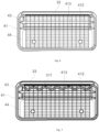
- an airbag door structure is mounted on an instrument panel D on a co-driver side of a vehicle V, and comprises a skin layer 1, a foamed layer 2, a framework 3, and a mesh fabric 4, wherein the mesh fabric 4 is fixedly connected below an airbag door region of the framework 3, the foamed layer 2 is covered above the framework 3 to provide a soft touch of the instrument panel D, and the skin layer 1 is covered above the foamed layer 2 to provide a cortical appearance of the instrument panel D.
- the airbag located below the mesh fabric 4 is ignited and opened from the inside of the instrument panel D and inflated to protect the co-driver.
- the mesh fabric 4 of the airbag door structure is connected and fixed on the inner side of the framework 3 facing the airbag.
- the framework 3 comprises an integrally formed door cover 31 and a side panel 32, the junction of which is formed as a hinge 33, and the door cover 31 is positioned in the opening channel of the airbag to open around the hinge 33 in the event of a ignition.
- the recess 311 is formed in the bottom surface of the door cover 31 close to the hinge 33, thereby improving the bonding force between the mesh fabric 4 and the door cover 31.
- the recess 311 is a wave groove extending parallel to the hinge 33. It should be understood that the waveforms herein are not limited to the shapes shown in the figures, nor to the continuous extension shown in the figures, and that it is possible to provide the recess, for example, from discrete semi-circular arc segments.
- the door cover 31 is provided with a first pressing rib 312 and a second pressing rib 313, both extending parallel to the hinge 33, for pressing the mesh fabric 4 against the framework 3, and a recess 311 located between the hinge 33 and the first pressing rib 312, thereby preventing the first pressing rib 312 from being damaged, thereby preventing the first pressing rib 312 puncturing the airbag after rupture during airbag deployment, resulting in a safety hazard.
- the recess 311 can not only improve the bonding force between the mesh fabric 4 in the recess 311 and the door cover 31, but also confine the mesh fabric 4 at the first pressing ribs 312 to the bottom of the first pressing ribs 312.
- the inventors have surprisingly found that if the recess 311 is omitted, the mesh fabric 4 will not be able to conform to the door cover 31 during the injection molding of the first pressing rib 312, but will float to a position in the middle of the first pressing rib 312, which is clearly detrimental to the strength of the first pressing rib 312, thereby possibly leading to the above mentioned safety risk of puncturing the airbag after rupture.
- the minimum distance of the recess 311 from the hinge 33 is between 3 and 5 mm and the distance of the first pressing rib 312 from the hinge 33 is between 10 and 30 mm.
- the depth of the recess 311 is between 1 and 2 mm. In the present embodiment, the depth of the recess 311 is 1.5 mm.
- the width of the recess 311 is between 2 and 4 mm. In the present embodiment, the width of the recess 311 is 3 mm.
- the mesh fabric 4 is connected to the framework 3 by means of inserted injection molding, and during the inserted injection molding, a part of the resin penetrates through the mesh fabric 4 to form a reinforcing rib at the outer surface of the mesh fabric corresponding to the recess 311, so as to improve the bonding force between the mesh fabric 4 and the door cover 31.
- the resin is advantageously exuded, and the reinforcing ribs are provided by the local gathering structure 311a, further increasing the peeling force.
- the peeling energy of the mesh fabric 4 and the door cover 31 is increased by 35.1%. It is ensured that the first pressing rib 312 is not damaged, increasing the design safety margin.
- the mesh fabric 4 connected to the side panel 32 has a first lifting ring 41 and a second lifting ring 42 which are connected in series, and such a double-lifting-ring mesh fabric is connected to the framework 3 by means of inserted injection molding, so as to facilitate more absorption of impact energy of the airbag when the airbag is deployed, thereby preventing the first pressing rib 312 from being damaged to cause the mesh fabric 4 to be detached from the door cover 31.
- the deploying energy absorption process of the functional zone mesh fabric 4 of the invention comprises three stages.
- the first stage is the breaking of the warp thread 41a and the subsequent deploying of the first lifting ring 41.
- the second stage is the peeling of the intermediate section 4a between the first lifting ring 41 and the second lifting ring 42 from the side panel 32.
- the third stage is the breaking of the warp thread 42a and the subsequent deploying of the second lifting ring 42, and the energy absorption effect is greatly improved.
- the energy absorption is increased by at least more than one time with respect to the single lifting ring mesh fabric, and the explosion stability coefficient is significantly improved.
- the mesh fabric 4 connected on the door cover 31 comprises a first region 43 and a second region 44, wherein the first region 43 is disposed close to the hinge 33, preferably 15 to 20 mm from the hinge 33, and the second region 44 is disposed away from the hinge 33.
- the mesh fabric 4 of the first region 43 has a first weft density and the mesh fabric 4 of the second region 44 has a second weft density, the first weft density being less than the second weft density.
- the first weft density is 3 threads per 10 mm or less
- the second weft density is 5 to 7 threads per 10 mm
- the preferred density is 6 threads per 10 mm.
- the number of weft knitting of the mesh fabric 4 in the first region 43 is reduced, and after the density is reduced, the molten resin forming the framework 3 in the inserted injection molding process penetrates through the mesh fabric 4 at the recess edge portion, so that ribs similar to the shape of the recess 311 are formed on the side of the mesh fabric 4 away from the door cover 31, and these ribs can further improve the bonding force between the mesh fabric 4 and the door cover 31; the number of weft knitting of the mesh fabric 4 in the second region 44 ensures the stiffness of the mesh fabric 4 at the time of injection molding.
- the first pressing rib 412 is located in the first region 43, thereby preventing the first pressing rib 312 from being damaged and preventing the mesh fabric 4 from being detached from the door cover 31.
- the invention may comprise conventional techniques (e.g. techniques implemented and/or integrated in exemplary embodiments, modifications, variations, combinations, equivalents) or may comprise any other suitable techniques (present and/or future) having the ability to perform the functions and processes/operations described in the specification and/or illustrated in the drawings. All such techniques (e.g. techniques implemented in embodiments, modifications, variations, combinations, equivalents, etc.) are considered to be within the scope of the invention of the patent document.
Landscapes
- Engineering & Computer Science (AREA)
- Mechanical Engineering (AREA)
- Air Bags (AREA)
- Injection Moulding Of Plastics Or The Like (AREA)
Applications Claiming Priority (2)
| Application Number | Priority Date | Filing Date | Title |
|---|---|---|---|
| CN202210933473.1A CN115285060B (zh) | 2022-08-04 | 2022-08-04 | 一种气囊门结构 |
| PCT/CN2023/111065 WO2024027801A1 (fr) | 2022-08-04 | 2023-08-03 | Structure de porte à airbag, composant intérieur de véhicule et procédé de fabrication |
Publications (2)
| Publication Number | Publication Date |
|---|---|
| EP4566896A1 true EP4566896A1 (fr) | 2025-06-11 |
| EP4566896A4 EP4566896A4 (fr) | 2025-12-24 |
Family
ID=83826941
Family Applications (1)
| Application Number | Title | Priority Date | Filing Date |
|---|---|---|---|
| EP23849505.5A Pending EP4566896A4 (fr) | 2022-08-04 | 2023-08-03 | Structure de porte à airbag, composant intérieur de véhicule et procédé de fabrication |
Country Status (4)
| Country | Link |
|---|---|
| US (1) | US12545208B2 (fr) |
| EP (1) | EP4566896A4 (fr) |
| CN (1) | CN115285060B (fr) |
| WO (1) | WO2024027801A1 (fr) |
Families Citing this family (3)
| Publication number | Priority date | Publication date | Assignee | Title |
|---|---|---|---|---|
| CN115285060B (zh) | 2022-08-04 | 2023-06-23 | 上海延锋金桥汽车饰件系统有限公司 | 一种气囊门结构 |
| CN116788194B (zh) * | 2023-06-05 | 2025-09-26 | 东风汽车集团股份有限公司 | 一种副驾驶组合材料气囊框的设计结构及设计方法 |
| WO2025238193A1 (fr) * | 2024-05-15 | 2025-11-20 | Rsw Gmbh | Textile de charnière et charnière de coussin de sécurité gonflable |
Family Cites Families (33)
| Publication number | Priority date | Publication date | Assignee | Title |
|---|---|---|---|---|
| US5393089A (en) * | 1993-09-01 | 1995-02-28 | Chrysler Corporation | Vehicle air bag cover |
| US5685930A (en) * | 1995-03-31 | 1997-11-11 | Davidson Textron Inc. | Motor vehicle instrument panel with flexible tethering hinged air bag deployment door |
| US5639115A (en) * | 1995-12-12 | 1997-06-17 | Trw Vehicle Safety Systems Inc. | Deployment door assembly for an inflatable vehicle occupant restraint |
| DE19616942B4 (de) * | 1996-04-27 | 2005-06-16 | Mst Automotive Gmbh Automobil-Sicherheitstechnik | Airbag-Abdeckkappe |
| DE10018893A1 (de) * | 2000-04-14 | 2001-10-25 | Acts Gmbh & Co Kg | Instrumententafel für ein Kraftfahrzeug und Verfahren zur Herstellung eines Kunststoff-Trägers für eine Instrumententafel |
| FR2811952B1 (fr) * | 2000-07-18 | 2003-01-31 | Ecia Equip Composants Ind Auto | Equipement de vehicule automobile pour sac gonflable, ensemble correspondant et son procede de fabrication |
| EP1487672A4 (fr) * | 2002-03-28 | 2006-09-13 | Collins & Aikman Automotive Co | Ensemble attache dynamique/commandee pour porte d'airbag |
| DE10223302A1 (de) * | 2002-05-24 | 2003-12-04 | Peguform Gmbh & Co Kg | Airbagabdeckung |
| US20040043683A1 (en) * | 2002-09-04 | 2004-03-04 | Intier Automotive Inc. | Method of manufacturing a trim part under low pressure operating conditions |
| JP2005199766A (ja) * | 2004-01-13 | 2005-07-28 | Toyoda Gosei Co Ltd | 膝保護用エアバッグ装置 |
| US7210700B2 (en) * | 2004-08-24 | 2007-05-01 | Visteon Global Technologies, Inc | Hinge mechanism for inflatable restraint apparatus |
| EP1754635A1 (fr) * | 2005-08-11 | 2007-02-21 | Peguform Bohemia k.s. | Tableau de bord avec couvercle de sac gonflable intégrée et procédé pour sa fabrication |
| CN1915713A (zh) * | 2005-08-17 | 2007-02-21 | 佩格福尔姆波西米亚公司 | 带整体式安全气囊盖的仪表面板 |
| KR101230829B1 (ko) * | 2010-10-29 | 2013-02-07 | 현대자동차주식회사 | 조수석 에어백의 도어힌지 구조 |
| FR3007347B1 (fr) * | 2013-06-24 | 2017-02-24 | Faurecia Interieur Ind | Procede pour mouler par injection un boitier de coussin de securite gonflable. |
| FR3007350B1 (fr) * | 2013-06-24 | 2015-06-05 | Faurecia Interieur Ind | Dispositif de securite pour vehicule. |
| DE102013017382B4 (de) * | 2013-10-21 | 2022-06-15 | Lisa Dräxlmaier GmbH | Innenverkleidungsteil für Fahrzeuge und Verfahren zum Herstellen eines solchen Innenverkleidungsteils |
| FR3013011B1 (fr) * | 2013-11-14 | 2017-04-14 | Renault Sas | Dispositif d'ouverture d'un sac gonflable dans un vehicule automobile |
| EP3034361B1 (fr) * | 2014-12-16 | 2018-04-18 | Volvo Car Corporation | Couvercle d'airbag et procédé de fabrication associé |
| DE102017100330A1 (de) * | 2017-01-10 | 2018-07-12 | International Automotive Components Group Gmbh | Airbag-Anordnung und Verfahren zu ihrer Herstellung |
| JP6563082B1 (ja) * | 2018-06-21 | 2019-08-21 | カルソニックカンセイ株式会社 | エアバッグリッド補強部材及びその製造方法 |
| US11840188B2 (en) * | 2018-06-28 | 2023-12-12 | Shanghai Yanfeng Jinqiao Automotive Trim Systems Co. Ltd. | Vehicle interior component |
| EP3814177B1 (fr) * | 2018-06-28 | 2025-01-08 | Shanghai Yanfeng Jinqiao Automotive Trim Systems Co. Ltd | Élément de garniture de véhicule |
| CN208813152U (zh) * | 2018-07-27 | 2019-05-03 | 力帆实业(集团)股份有限公司 | 一种安全气囊组件 |
| CN209079401U (zh) | 2018-09-21 | 2019-07-09 | 嘉兴市牛大科技有限公司 | 一种用于汽车仪表板安全气囊框的网布 |
| CN109306563B (zh) * | 2018-11-12 | 2020-07-07 | 上海捷英途新材料科技有限公司 | 一种汽车安全气囊铰链网布 |
| CN209813910U (zh) * | 2019-03-01 | 2019-12-20 | 上海延锋金桥汽车饰件系统有限公司 | 一种软质仪表板 |
| CN111071196A (zh) * | 2020-01-07 | 2020-04-28 | 上海延锋金桥汽车饰件系统有限公司 | 包含安全气囊门铰链的用于汽车内部的饰件 |
| CN112941694A (zh) | 2021-03-29 | 2021-06-11 | 嘉兴市牛大科技有限公司 | 用于安全气囊的网布 |
| CN215706181U (zh) | 2021-06-30 | 2022-02-01 | 长春富维安道拓汽车饰件系统有限公司 | 一种带有吸能单元的汽车副驾驶气囊支架总成 |
| CN118632800A (zh) * | 2022-01-28 | 2024-09-10 | 延锋国际汽车技术有限公司 | 用于车辆内部的部件 |
| CN119497688A (zh) * | 2022-07-11 | 2025-02-21 | 延锋国际汽车技术有限公司 | 用于车辆内部的部件 |
| CN115285060B (zh) * | 2022-08-04 | 2023-06-23 | 上海延锋金桥汽车饰件系统有限公司 | 一种气囊门结构 |
-
2022
- 2022-08-04 CN CN202210933473.1A patent/CN115285060B/zh active Active
-
2023
- 2023-08-03 EP EP23849505.5A patent/EP4566896A4/fr active Pending
- 2023-08-03 WO PCT/CN2023/111065 patent/WO2024027801A1/fr not_active Ceased
-
2025
- 2025-02-03 US US19/044,026 patent/US12545208B2/en active Active
Also Published As
| Publication number | Publication date |
|---|---|
| CN115285060B (zh) | 2023-06-23 |
| US20250178556A1 (en) | 2025-06-05 |
| EP4566896A4 (fr) | 2025-12-24 |
| CN115285060A (zh) | 2022-11-04 |
| WO2024027801A1 (fr) | 2024-02-08 |
| US12545208B2 (en) | 2026-02-10 |
Similar Documents
| Publication | Publication Date | Title |
|---|---|---|
| EP4566896A1 (fr) | Structure de porte à airbag, composant intérieur de véhicule et procédé de fabrication | |
| KR101603664B1 (ko) | 내부 패널링부 | |
| US6523854B1 (en) | Vehicle part with an airbag device and method for producing a vehicle part of this type | |
| KR102726793B1 (ko) | 에어백 도어의 힌지구조 | |
| US8191924B2 (en) | Dashboard | |
| KR100288614B1 (ko) | 에어백 모듈용 커버링 | |
| US9895828B2 (en) | Vehicle interior panel for covering an airbag and manufacturing method | |
| US6651998B1 (en) | Safety covering for an airbag | |
| EP2263922B1 (fr) | Partie intérieure de véhicule | |
| US8047561B2 (en) | Airbag cover | |
| KR102659563B1 (ko) | 에어백 커버장치 | |
| US7059652B2 (en) | Automobile sun visor stay that maintains safety in emergencies | |
| KR102680264B1 (ko) | 스크림 일체형 에어백 도어 및 그 제조방법 | |
| KR102789100B1 (ko) | 조수석 에어백 장치 | |
| US7914035B2 (en) | Headliner system | |
| CN108372624A (zh) | 制造用于机动车辆的复合表皮泡沫载体部件的方法和用于机动车辆的复合表皮泡沫载体部件 | |
| JP4614797B2 (ja) | エアバッグドア | |
| CN101423046B (zh) | 车辆仪表板 | |
| JP2007030841A (ja) | エアバッグドア | |
| KR0151983B1 (ko) | 자동차의 조수석 에어백 덮개의 열림장치 | |
| KR20050047362A (ko) | 자동차의 사이드에어백 장착용 브라켓트 | |
| KR100535757B1 (ko) | 은폐식 에어백 도어의 전개구조 | |
| KR100220772B1 (ko) | 승객용 에어백 | |
| KR100499949B1 (ko) | 은폐식 에어백 도어의 전개구조 | |
| KR200193452Y1 (ko) | 조수석 에어백 커버의 개방 구조 |
Legal Events
| Date | Code | Title | Description |
|---|---|---|---|
| STAA | Information on the status of an ep patent application or granted ep patent |
Free format text: STATUS: THE INTERNATIONAL PUBLICATION HAS BEEN MADE |
|
| PUAI | Public reference made under article 153(3) epc to a published international application that has entered the european phase |
Free format text: ORIGINAL CODE: 0009012 |
|
| STAA | Information on the status of an ep patent application or granted ep patent |
Free format text: STATUS: REQUEST FOR EXAMINATION WAS MADE |
|
| 17P | Request for examination filed |
Effective date: 20250130 |
|
| AK | Designated contracting states |
Kind code of ref document: A1 Designated state(s): AL AT BE BG CH CY CZ DE DK EE ES FI FR GB GR HR HU IE IS IT LI LT LU LV MC ME MK MT NL NO PL PT RO RS SE SI SK SM TR |
|
| DAV | Request for validation of the european patent (deleted) | ||
| DAX | Request for extension of the european patent (deleted) | ||
| A4 | Supplementary search report drawn up and despatched |
Effective date: 20251126 |
|
| RIC1 | Information provided on ipc code assigned before grant |
Ipc: B60R 21/215 20110101AFI20251120BHEP Ipc: B60R 21/205 20110101ALI20251120BHEP |