EP4567005A1 - Vorrichtung zum filtern und reinigen von grauwasser oder anderem abwasser zur erzeugung einer neuen, sauberen und sicheren wasserquelle mittels eines biologischen filters - Google Patents
Vorrichtung zum filtern und reinigen von grauwasser oder anderem abwasser zur erzeugung einer neuen, sauberen und sicheren wasserquelle mittels eines biologischen filters Download PDFInfo
- Publication number
- EP4567005A1 EP4567005A1 EP22953395.5A EP22953395A EP4567005A1 EP 4567005 A1 EP4567005 A1 EP 4567005A1 EP 22953395 A EP22953395 A EP 22953395A EP 4567005 A1 EP4567005 A1 EP 4567005A1
- Authority
- EP
- European Patent Office
- Prior art keywords
- biocarrier
- water
- tank
- ring
- container
- Prior art date
- Legal status (The legal status is an assumption and is not a legal conclusion. Google has not performed a legal analysis and makes no representation as to the accuracy of the status listed.)
- Pending
Links
Images









Classifications
-
- C—CHEMISTRY; METALLURGY
- C02—TREATMENT OF WATER, WASTE WATER, SEWAGE, OR SLUDGE
- C02F—TREATMENT OF WATER, WASTE WATER, SEWAGE, OR SLUDGE
- C02F3/00—Biological treatment of water, waste water, or sewage
- C02F3/02—Aerobic processes
- C02F3/10—Packings; Fillings; Grids
- C02F3/109—Characterized by the shape
-
- C—CHEMISTRY; METALLURGY
- C02—TREATMENT OF WATER, WASTE WATER, SEWAGE, OR SLUDGE
- C02F—TREATMENT OF WATER, WASTE WATER, SEWAGE, OR SLUDGE
- C02F3/00—Biological treatment of water, waste water, or sewage
- C02F3/02—Aerobic processes
- C02F3/10—Packings; Fillings; Grids
- C02F3/101—Arranged-type packing, e.g. stacks, arrays
-
- C—CHEMISTRY; METALLURGY
- C02—TREATMENT OF WATER, WASTE WATER, SEWAGE, OR SLUDGE
- C02F—TREATMENT OF WATER, WASTE WATER, SEWAGE, OR SLUDGE
- C02F3/00—Biological treatment of water, waste water, or sewage
- C02F3/02—Aerobic processes
- C02F3/10—Packings; Fillings; Grids
- C02F3/105—Characterized by the chemical composition
- C02F3/108—Immobilising gels, polymers or the like
-
- C—CHEMISTRY; METALLURGY
- C02—TREATMENT OF WATER, WASTE WATER, SEWAGE, OR SLUDGE
- C02F—TREATMENT OF WATER, WASTE WATER, SEWAGE, OR SLUDGE
- C02F3/00—Biological treatment of water, waste water, or sewage
- C02F3/02—Aerobic processes
- C02F3/12—Activated sludge processes
- C02F3/20—Activated sludge processes using diffusers
- C02F3/201—Perforated, resilient plastic diffusers, e.g. membranes, sheets, foils, tubes, hoses
-
- B—PERFORMING OPERATIONS; TRANSPORTING
- B01—PHYSICAL OR CHEMICAL PROCESSES OR APPARATUS IN GENERAL
- B01J—CHEMICAL OR PHYSICAL PROCESSES, e.g. CATALYSIS OR COLLOID CHEMISTRY; THEIR RELEVANT APPARATUS
- B01J2219/00—Chemical, physical or physico-chemical processes in general; Their relevant apparatus
- B01J2219/30—Details relating to random packing elements
- B01J2219/302—Basic shape of the elements
- B01J2219/30219—Disk
-
- B—PERFORMING OPERATIONS; TRANSPORTING
- B01—PHYSICAL OR CHEMICAL PROCESSES OR APPARATUS IN GENERAL
- B01J—CHEMICAL OR PHYSICAL PROCESSES, e.g. CATALYSIS OR COLLOID CHEMISTRY; THEIR RELEVANT APPARATUS
- B01J2219/00—Chemical, physical or physico-chemical processes in general; Their relevant apparatus
- B01J2219/30—Details relating to random packing elements
- B01J2219/302—Basic shape of the elements
- B01J2219/30223—Cylinder
-
- B—PERFORMING OPERATIONS; TRANSPORTING
- B01—PHYSICAL OR CHEMICAL PROCESSES OR APPARATUS IN GENERAL
- B01J—CHEMICAL OR PHYSICAL PROCESSES, e.g. CATALYSIS OR COLLOID CHEMISTRY; THEIR RELEVANT APPARATUS
- B01J2219/00—Chemical, physical or physico-chemical processes in general; Their relevant apparatus
- B01J2219/30—Details relating to random packing elements
- B01J2219/304—Composition or microstructure of the elements
- B01J2219/30466—Plastics
-
- C—CHEMISTRY; METALLURGY
- C02—TREATMENT OF WATER, WASTE WATER, SEWAGE, OR SLUDGE
- C02F—TREATMENT OF WATER, WASTE WATER, SEWAGE, OR SLUDGE
- C02F2103/00—Nature of the water, waste water, sewage or sludge to be treated
- C02F2103/002—Grey water, e.g. from clothes washers, showers or dishwashers
-
- C—CHEMISTRY; METALLURGY
- C02—TREATMENT OF WATER, WASTE WATER, SEWAGE, OR SLUDGE
- C02F—TREATMENT OF WATER, WASTE WATER, SEWAGE, OR SLUDGE
- C02F2201/00—Apparatus for treatment of water, waste water or sewage
- C02F2201/009—Apparatus with independent power supply, e.g. solar cells, windpower or fuel cells
-
- C—CHEMISTRY; METALLURGY
- C02—TREATMENT OF WATER, WASTE WATER, SEWAGE, OR SLUDGE
- C02F—TREATMENT OF WATER, WASTE WATER, SEWAGE, OR SLUDGE
- C02F2203/00—Apparatus and plants for the biological treatment of water, waste water or sewage
- C02F2203/006—Apparatus and plants for the biological treatment of water, waste water or sewage details of construction, e.g. specially adapted seals, modules, connections
-
- C—CHEMISTRY; METALLURGY
- C02—TREATMENT OF WATER, WASTE WATER, SEWAGE, OR SLUDGE
- C02F—TREATMENT OF WATER, WASTE WATER, SEWAGE, OR SLUDGE
- C02F2209/00—Controlling or monitoring parameters in water treatment
- C02F2209/02—Temperature
-
- C—CHEMISTRY; METALLURGY
- C02—TREATMENT OF WATER, WASTE WATER, SEWAGE, OR SLUDGE
- C02F—TREATMENT OF WATER, WASTE WATER, SEWAGE, OR SLUDGE
- C02F2209/00—Controlling or monitoring parameters in water treatment
- C02F2209/05—Conductivity or salinity
-
- C—CHEMISTRY; METALLURGY
- C02—TREATMENT OF WATER, WASTE WATER, SEWAGE, OR SLUDGE
- C02F—TREATMENT OF WATER, WASTE WATER, SEWAGE, OR SLUDGE
- C02F2209/00—Controlling or monitoring parameters in water treatment
- C02F2209/06—Controlling or monitoring parameters in water treatment pH
-
- C—CHEMISTRY; METALLURGY
- C02—TREATMENT OF WATER, WASTE WATER, SEWAGE, OR SLUDGE
- C02F—TREATMENT OF WATER, WASTE WATER, SEWAGE, OR SLUDGE
- C02F2209/00—Controlling or monitoring parameters in water treatment
- C02F2209/11—Turbidity
-
- C—CHEMISTRY; METALLURGY
- C02—TREATMENT OF WATER, WASTE WATER, SEWAGE, OR SLUDGE
- C02F—TREATMENT OF WATER, WASTE WATER, SEWAGE, OR SLUDGE
- C02F2303/00—Specific treatment goals
- C02F2303/02—Odour removal or prevention of malodour
-
- C—CHEMISTRY; METALLURGY
- C02—TREATMENT OF WATER, WASTE WATER, SEWAGE, OR SLUDGE
- C02F—TREATMENT OF WATER, WASTE WATER, SEWAGE, OR SLUDGE
- C02F2303/00—Specific treatment goals
- C02F2303/26—Reducing the size of particles, liquid droplets or bubbles, e.g. by crushing, grinding, spraying, creation of microbubbles or nanobubbles
-
- Y—GENERAL TAGGING OF NEW TECHNOLOGICAL DEVELOPMENTS; GENERAL TAGGING OF CROSS-SECTIONAL TECHNOLOGIES SPANNING OVER SEVERAL SECTIONS OF THE IPC; TECHNICAL SUBJECTS COVERED BY FORMER USPC CROSS-REFERENCE ART COLLECTIONS [XRACs] AND DIGESTS
- Y02—TECHNOLOGIES OR APPLICATIONS FOR MITIGATION OR ADAPTATION AGAINST CLIMATE CHANGE
- Y02W—CLIMATE CHANGE MITIGATION TECHNOLOGIES RELATED TO WASTEWATER TREATMENT OR WASTE MANAGEMENT
- Y02W10/00—Technologies for wastewater treatment
- Y02W10/10—Biological treatment of water, waste water, or sewage
Definitions
- the present invention is related to the water reuse industry, specifically, it refers to a device for the reuse of wastewater, such as gray water, which aimed at providing a new water source in places with water shortage or deficit, thus reducing water consumption.
- the water crisis is a growing and global problem. It is projected that by 2030 there will be a 40% water deficit worldwide. Particularly, Chile is one of the most heavily impacted countries, as 72% of the territory is affected by drought and more than 1 million Chileans do not have access to water. This scenario requires action, so it is urgent to find new water sources.
- An attractive alternative is the reuse of wastewater produced by human activity. Between 40-75% of the total water consumed per capita corresponds to wastewater, mainly gray water used in showers, sinks and washing machines. Although the low level of wastewater contamination or graywater allows it to be reused, in practice it is almost entirely wasted due to the lack of sustainable, efficient, simple and affordable technologies that can be implemented locally or purchased by customers.
- US20150191365 describes a grey water recovery and reuse system comprising a body for collecting, conditioning and discharging grey water, comprising an inlet connected to a grey water source; a solids filter for the grey water, positioned at the inlet of the body; a waste outlet adjacent to and under the filter aimed at removing such solids; a pond to receive the filtered graywater; a disinfectant to disinfect the filtered graywater; a pump to discharge the conditioned graywater from the pond; a discharge connection to the sewerage system; a connection to a fresh water source; and a control system aimed at controlling the operation of the system.
- the system allows treating the water in a single body or pond; however, it does not use microorganisms in substrates that allow metabolizing the contaminants in the gray water, where the substrates are constantly agitated by means of an aeration device that favors the interaction between the microorganisms and the water to be filtered.
- none of the above documents discloses a device for wastewater filtration and purification, such as greywater, which allows reusing such water with an efficient, simple and affordable configuration to be implemented locally or by a family, up to large volumes of water, using a plurality of biocarriers aimed at maximizing the contact between the water to be treated and the microorganisms on the substrates and thus improve the oxygen transfer to such microorganisms, which promotes their aerobic metabolism and, consequently, improves water purification process.
- None of said documents disclose carriers or biocarriers featuring a configuration of cavities and blades aimed at encouraging microorganisms growth and to ensure hydrodynamic performance for the interaction between the biocarrier and the water.
- the invention relates to an integrated device for the filtration and purification of wastewater, such as gray water, which allows the reuse of such water thus generating a new water source.
- the device allows the revaluation as a resource of wastewater, such as gray water, which is generally wasted, thus generating a new, clean and safe water source, which allows the saving of water consumption. This is of particular relevance in places with drought, water shortage or water deficit.
- Another objective of the invention is to provide a device that allows wastewater treatment, such as gray water, in a sustainable manner and free of toxic by-products.
- Another objective of the invention is to provide a water source that allows the regeneration of green areas and crops that have been affected by the lack of available water.
- the device consists of a biological filter that uses a biofilter containing microorganisms, established on substrates, capable of removing pollutants and/or impurities from wastewater, such as gray water.
- the design of the substrates used in the device improves its hydrodynamic behavior, achieving a greater interaction with water and air that maximizes the contact between the water to be treated and the microorganisms on the substrates and improves the transfer of oxygen to these microorganisms, allowing to favor their aerobic metabolism and, consequently, improves the purification process of wastewater, particularly gray water.
- the device treats water, thus allowing 100% of the water to be reused for irrigation, toilet flushing and/or industrial uses, reducing on average between 40-70% of water consumption, providing economic and water savings. It is an effective, compact, sustainable technology, easy to operate, with low maintenance, low cost compared to other biological technologies and affordable for people.
- the device is designed to be used by a wide range of users for local or single-family implementation up to large volumes of water, such as urban or rural families, farmers, companies that want to reduce water consumption, institutions and construction/real estate/industrial companies, or any consumer interested in reducing their water footprint.
- the integrated device for reusing wastewater, such as gray water, that allows to obtain a new water source is a biological filtering device, comprising a tank for collecting the water to be treated; a biocarrier container comprising a plurality of biocarriers containing the grown microorganisms, which are responsible for purifying the water, thus becoming a biofilter; and an aeration unit to supply oxygen inside the tank aimed at promoting the aerobic metabolism of the microorganisms, thus preventing the occurrence of bad odors and keeping the biocarriers in constant agitation for their interaction with the water.
- the aeration unit provides constant agitation of the biocarriers thus allowing the interaction between the microorganisms and the water for filtration and purification.
- the aeration unit injects air for promoting the aerobic metabolism of the microorganisms in the biofilter, due to the addition of oxygen in the device.
- the biocarrier design is developed in such a way that it provides a hydrodynamic performance aimed at facilitating the wastewater biofiltration process, particularly graywater, so that the biocarriers achieve a greater interaction with water and air, as well as with oxygen and aerobic metabolism.
- the tank comprises an inlet for routing the water to be treated and for discharging the water after it has been filtered and purified.
- the tank may include an outlet separated from the inlet for discharging the water once it has been filtered and purified.
- the device may optionally include a pre-filter at its inlet aimed at removing particles and suspended solids in the water to be treated prior to its entry into the tank.
- the device collects wastewater, in particular gray water, from showers, bathtubs, hand washing and/or laundry to be treated until it is purified.
- microorganisms are embedded in biocarriers that correspond to an inert and light substrate, which allows the growth of microorganisms inside, which are designed for their movement in the water thus favoring the interaction between the microorganisms and the water, and ensuring purification of the treated water.
- the biocarrier container confines the grown microorganisms on a plurality of biocarriers and it is mounted inside the tank.
- the biocarrier container includes attachment means allowing the container to be anchored inside the tank in such a way that it is suspended or floating without being in contact with the walls of the tank.
- the device may comprise connections that allow routing the water to be treated from its source to the collection tank.
- the device may also include water pumps to discharge purified water to and from the tank, respectively, to facilitate water transportation to be treated and discharge of purified water to and from the tank.
- the device may optionally include a real-time monitoring system, aimed at measuring water quality parameters by using sensors that are integrated in a centralized circuit.
- the invention relates to an integrated device (1) for the filtration and purification of wastewater, such as gray water, which allows the reuse of such water to aimed at generating a new water source
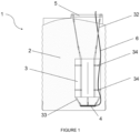
- the integrated device (1) corresponds to a biological type filtering device, as shown in figure 1 , comprising a tank (2) for the collection of the water to be treated, a biocarrier container (3), placed inside the tank (2), comprising a plurality of biocarriers containing microorganisms grown which purify the water; thus becoming a biofilter; and an aeration unit configured to supply oxygen inside of the tank in order to promote the aerobic metabolism of the microorganisms, prevent the appearance of bad odors and to keep the biocarriers in constant agitation to promote their interaction with the water.
- the tank (2) includes an inlet or opening (5) for routing the water to be treated and for discharging the water once it has been filtered and purified.
- the tank (2) may include an outlet or discharge separate from the inlet or opening (5) for discharging the water once filtered and purified.
- the microorganisms grow in the form of biofilms.
- the device collects the gray water from showers, bathtubs, hand washing and/or laundry to be treated until its purification is achieved.
- the biocarrier container (3) keeps the grown microorganisms confined on the plurality of biocarriers, as shown in figure 2 , comprising an elongated body (31), made of a water permeable material, with a top end and a bottom end, opposite to each other, wherein the bottom end comprises connecting means (33) for connection to the aeration unit.
- the upper end of the biocarrier container (3) comprises fastening means (32) that allow anchoring or mounting the biocarrier container (3) to the tank (2), wherein the fixing means (32) allow anchoring the biocarrier container (3) to the opening (5) of the tank (2), such that the biocarrier container (3) is suspended or floating inside the tank (2) without being in contact with the walls thereof and aligned with its opening (5).
- the biocarrier container (3) can be suspended at different heights inside the tank (2), between a position where the upper end of the body (31) matches the opening (5) of the tank to a position where the lower end of the body (31) is close to a lower wall of the tank (2), while the biocarrier container (3) is not in contact with any wall of the tank (2).
- the position of the biocarrier container (3) inside the tank (2) is determined by the fixing means (32), which can be fixed or adjustable.
- the fixing means (32) comprise at least two tie straps (321) at the upper end of the body (31) of the biocarrier container (3); at least two fixing elements (322) constituted by a support strap (323) whose ends include quick connectors (324) that attach to a tie strap (321) and to the opening (5) of the tank (2), respectively.
- the length of the support strap (323) determines the height at which the biocarrier container (3) is suspended, and may be of a fixed length to define a fixed suspension height or of variable or adjustable length to modify the position of the biocarrier container (3) inside the tank (2).
- the support straps (323) may include loops at their ends for attaching the quick connectors (324).
- the opening (5) of the tank (2) comprises at least two mounting hooks (51) that facilitate and secure the mounting or anchoring of the fixing means (32).
- the mounting hooks (51) can be connected with a quick connector (324) of the fastening elements (322) on the fixing means (32).
- the quick connectors (324) and the mounting hooks (51) are made of stainless material, such as, for instance, stainless steel.
- the body (31) of the biocarrier container (3) is a bag of porous material fabric of cylindrical shape comprising a closure (311), preferably of plastic, for access to the interior of the body (31) for placing and/or replacing the biocarriers.
- the porous material fabric is manufactured from recycled fabrics or from a material of plant origin.
- the biocarrier container (3) may include a ring at each end of said body (31).
- said rings are manufactured with planza (polyethylene pipe), a material designed to be in contact with water.
- said rings are made of stainless steel.
- the aeration unit comprises an air diffusing ring (4), attached to the biocarrier container (3) at the lower end of the body (31), connected to one end of an air hose (6), wherein the air hose (6) exits the tank (2) so that the other end is connected to a mini air compressor that injects air into the tank (2) through the air diffusing ring (4), wherein the air diffusing ring (4) comprises a support, in the form of a ring, coupled to a diffuser hose, circular in shape, from which air microbubbles emerge to supply oxygen into the tank (2) to promote the aerobic metabolism of the microorganisms and prevent the appearance of bad odors.
- the support of the air diffusing ring (4) is used to shape its structure, preferably made of stainless steel.
- the bubbles generated by the air diffusing ring (4) maintain in constant agitation the plurality of biocarriers favoring the interaction between the microorganisms and the water for their filtration and purification.
- the position of the biocarrier container (3) inside the tank (2) is such that the air diffusing ring (4) is completely submerged, but is not in contact with the tank (2) in order to avoid the noise caused by the vibration of said ring (4), which may cause discomfort to the user.
- a mini compressor of at least 38 Watts for water treatment in a 1,000 liter tank and a mini compressor of at least 58 Watts for water treatment in a 2,000 liter tank it is possible to use a mini compressor of at least 38 Watts for water treatment in a 1,000 liter tank and a mini compressor of at least 58 Watts for water treatment in a 2,000 liter tank.
- the air diffusing ring (4) is attached to the biocarrier container (3) by connecting means (33) at the lower end of the body (31).
- the connecting means (33) comprise at least four support strips (331), wherein one end of said strips (331) is attached to the lower end of the body (31) and the other end is connected with the air diffusing ring (4).
- the connection between the connecting means (33) and the air diffusing ring (4) is made using a hook (332) at each end of the support strips (331).
- the support strips (331) may include a loop at their ends for positioning the hook (332).
- the hooks (332) are made of stainless steel.
- the connection between the connecting means (33) and the air diffusing ring (4) is made by using cable ties.
- a portion of the air hose (6) is fixed to the body (31) of the biocarrier container (3) using at least one transverse pin (34) near each end of said body (31), such that said portion of the air hose (6) remains parallel to the longitudinal axis of the body (31).
- the air hose (6) is arranged inside the tank (2) without being attached to the biocarrier container (3).
- the tank (2) is substantially cylindrical and can have a vertical configuration, as in figure 1 , or a horizontal configuration, as in figure5 .
- the opening (5) is on the top face and in case the tank (2) is in a horizontal configuration, the opening (5) is on the top of the tank (2) corresponding to the curved surface or body of the cylinder.
- the biocarrier container (3) and the aeration unit are arranged equivalently.
- said biocarrier container (3) is arranged such that it is aligned with the opening (5) in the vertical direction.
- the opening (5) includes a protection means that prevents the entry of foreign matter or contaminants, said protection means being, in one embodiment, a lid (7) covering the opening (5).
- the device (1) may include a prefilter before or in the opening (5) for removing particles and suspended solids in the water to be treated before its entry into the tank (2) or after the treatment has been performed once the water has already been biofiltered.
- the device (1) may include connections that allow channeling the water to be treated from its source to the collection tank (2). Also, the device (1) may include water pumps to facilitate the feeding of water to be treated and the discharge of purified water to and from the tank (2), respectively. Optionally, the device (1) may include connections to communicate with a post-treatment tank for storing the treated or biofiltered water.
- the device (1) may further comprise a real-time monitoring system, which allows measuring water quality parameters through sensors that are integrated in a centralized circuit and controlling the operation of the device (1).
- the monitoring system measures at least the pH, turbidity, temperature and electrical conductivity of the water in the tank (2).
- the monitoring system further comprises a timer to generate different aeration cycles (on/off) to control the water purification time.
- the device (1) can be used for different purposes according to the user's needs, such as, for example, in low cost and high efficiency drip irrigation systems for the distribution of water to plant roots, toilet flushing or other domestic or industrial uses, according to the regulations of the country where the device is implemented.
- the device (1) may incorporate the use of renewable energy, e.g., solar energy by using solar panels, as a source of power supply with electricity to ensure autonomous operation.
- the device (1) can be automated by implementing a controller that allows the general operation of the device (1), the feeding/discharge of water, and optionally it may include water quality parameters.
- the microorganisms are established in the plurality of biocarriers that correspond to an inert and light substrate that allow the growth of microorganisms and colonization, where said biocarriers are designed for their movement in the water favoring the interaction between the microorganisms and the water, ensuring the purification of the water.
- the microorganisms correspond to specialized consortia that efficiently remove contaminants from wastewater, such as gray water, resist unfavorable conditions and adapt dynamically to variations in the composition of the water to be treated, to changes in pH, humidity and temperature.
- the microorganisms of the device (1) are environmental microorganisms that exhibit filtering capabilities and that can grow attached to a substrate.
- the microorganisms are previously enriched to ensure filtering efficiency, so as to have microorganisms grown on the substrate, to be included in the biocarrier container (3).
- the biomass growth of the microorganisms on the biocarriers should be at least 3 months to ensure filtering efficiency.
- the described device (1) can be implemented at various scales, such as, for example, for on-site reuse of shower water for toilet flushing, reuse of water from washing machines, or reuse of total gray water from a house, from a group of houses or larger buildings, or even on an industrial scale.
- the device (1) can be scaled for use with different flow rates of wastewater, particularly gray water, where the size of the tank (2) can be of any volume that is available depending on the user's needs.
- the device (1) allows the filtration of wastewater, particularly gray water, in a time between 12 to 24 hours depending on the volume of water.
- wastewater particularly gray water
- at least 1 kilo of biocarriers is required to filter 1,000 liters of gray water, requiring 12 hours for water treatment.
- the biocarriers are scaled proportionally to the biomass required for treatment. It is possible to accelerate the filtration process by adding biocarriers to the device (1) in order to reduce the treatment time while maintaining the volume of water to be treated.
- 1 ⁇ 4 of the biocarriers should be replaced every 18 months.
- the size of the biocarrier container (3) is adjusted to the amount of biocarriers used, so as to allows the movement of the biocarriers inside it when they are agitated by the aeration unit.
- the plurality of biocarriers can be inserted directly into the tank (2) without using the biocarrier container (3), allowing free circulation of the biocarriers with microorganisms inside the tank (2).
- the device (1) is integrated with a post-treatment disinfection system, including chlorination, ultraviolet light, ozone or other chemical and physicochemical methods.
- a post-treatment disinfection system including chlorination, ultraviolet light, ozone or other chemical and physicochemical methods.
- the biocarrier design was developed to provide a hydrodynamic performance that favors the biofiltration process of wastewater, such as gray water, so that the biocarriers achieve a greater interaction with water and air, thus, the oxygen that promotes aerobic metabolism.
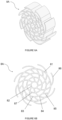
- the biocarrier comprises a hollow cylindrical outer ring (81); a polygonal inner ring (82), concentric with the outer ring (81) and located in the center thereof; an intermediate ring (83) between said polygonal inner ring (82) and the outer ring (81), concentric to these and separating the biocarrier into a plurality of sections; wherein, from each vertex of the polygon of the polygonal inner ring (82) a first curved rib (84) is projected connecting all the rings (81, 82, 83) of the biocarrier, wherein each first rib (84) further projects outwardly from the outer ring (81) forming vanes (86) or blades around the outer ring (81); and between each pair of first ribs (84) is disposed a second curved rib
- intersections formed between the rings (81, 82, 83) and the ribs (84, 85) form a plurality of cavities that increase the surface area of the biocarrier, thus improving the ability of microorganisms to grow inside it.
- the vanes (86) around the outer ring (81) of the biocarrier facilitate the rotation in the direction of the vanes (86) in order to generate a greater interaction between the biocarrier and the water, thus maximizing the contacts between the water to be treated and the biocarrier, as well as the transfer of oxygen to the microorganisms in order to promote their aerobic metabolism, and with it, the operation of the water purification process.
- the design of the biocarrier has a hydrodynamic performance that favors the biofiltration process of wastewater, such as gray water.
- the biocarrier further comprises at least one additional intermediate ring (87) between the intermediate ring (83) and the polygonal inner ring (82), wherein the radius of the intermediate ring (83) and the at least one additional intermediate ring (87) are such that all rings (81, 82, 83, 87) of the biocarrier are radially separated by the same distance.
- additional intermediate rings By including additional intermediate rings, additional cavities are formed which increase the surface area on which microorganisms can grow.
- the cavities and surface area of the biocarrier facilitate a greater growth of microorganisms, where the addition of vanes (86) contributes with new biomass adhesion points that allow the beginning of colonization in the context of aeration, movement and constant agitation of the biocarriers inside the biocarrier container (3) that is submerged in the water to be treated.
- This biocarrier design increases the surface area, the number of cavities and hydrodynamic interactions to enhance biomass growth, decreasing production costs and allowing local manufacturing.
- Figures 6A, 6B , 7A and 7B show embodiments of the biocarrier , according to the indicated elements.
- Figures 6A and 6B shows a first biocarrier (8A) comprising an outer ring (81); a polygonal inner ring (82) of octagonal shape; an intermediate ring (83) between said polygonal inner ring (82) and the outer ring (81); an additional intermediate ring (87), between the intermediate ring (83) and the polygonal inner ring (82); eight first curved ribs (84) extending from each vertex of the inner polygonal ring (82), forming eight vanes (86) around the outer ring (81); and eight second curved ribs (85), each disposed between each pair of first ribs (85) between the intermediate ring (83) and the outer ring (81).
- the first biocarrier (8A) includes thirty-three cavities and eight vanes (86).
- figures 7A and 7B show a second biocarrier (8B) comprising an outer ring (81); a polygonal inner ring (82) of octagonal shape; an intermediate ring (83) between said polygonal inner ring (82) and the outer ring (81); eight curved first ribs (84) projecting from each vertex of the polygonal inner ring (82), forming eight vanes (86) around the outer ring (81); and eight curved second ribs (85), each arranged between each pair of first ribs (85) between the intermediate ring (83) and the outer ring (81).
- the second biocarrier (8B) includes twenty-five cavities and eight vanes (86).
- the microorganisms used in the device (1) are adapted to grow attached to a plastic substrate, the biocarriers being fabricated from High Density Polyethylene (HDPE), Polyethylene Terephthalate Glycol (PETG) or Polylactic Acid (PLA).
- the biocarriers are manufactured using a 3D printer.
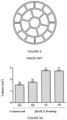
- biocarrier designs are considered according to the first biocarrier (8A) designated version 1 or V1, which includes thirty-three cavities and eight vanes; the second biocarrier (8B) designated version 2 or V2, which includes twenty-five cavities and eight vanes; and a third biocarrier designated K3 that corresponds to a commercially available biocarrier, which is shown in figure 8 and includes 19 cavities, with no vanes.
- the size of the biocarriers considered for testing are the same for the three designs where they have a cavity area of 6027 mm 2 for the first biocarrier (8A) 5650 mm 2 for the second biocarrier (8B) and 3309 mm 2 for the K3 biocarrier.
- volume, surface area and mass were measured for each version of the Biocarrier.
- the commercial version K3 (HDPE) was observed to have the lowest volume of all biocarrier versions.
- the K3 version has lower volume (in all its materials) than V1 and V2.
- V1 has the same volume as V2 in PLA material, but V1 has a significantly larger volume in PETG material.
- PETG material occupies more volume than PLA.
- table 1 shows the number of cavity and surface area for the 3 biocarrier geometries considered, where it is obtained that both V1 and V2, have a greater number of internal cavities, with respect to K3, in particular, V1 increases by 73% and V2 by 31%.
- the new versions of biocarriers have a greater surface area with respect to K3, where V1 increases by 82% and V2 increases by 70%.
- Table 1 Number of cavities and surface area for biocarriers.
- K3 V1 V2 Number of inner cavities 19 33 25 Number of outer cavities 0 8 8 Surface Area 3309 mm 2 6027 mm 2 5650 mm 2
- the commercial K3-HDPE Biocarrier is the lightest of all, which makes sense since it is the least dense material (0.95 g/cm 3 of HDPE vs. 1.24 g/cm 3 of PLA vs. 1.27 g/cm 3 of PETG).
- the biocarriers 3D printed with PETG are heavier than those 3D printed with PLA (same version), which is also explained according to the densities of the materials.
- the weight of biocarrier V1 is higher than that of V2, and the weight of V2 in turn is higher than the weight of printed K3. This is explained by the fact that V1 has the largest surface area and thus has more printed material/unit. It is followed in surface area by V2 and then K3, following the same logic.
- one of the aspects sought with the new biocarrier designs was to increase the surface area.
- the theoretical surface area results correlated well with the volume results. It was found that the volume of the new biocarrier designs increased. In addition, it was found that, as expected, as the surface area of the new biocarriers increased, the mass of each piece increased, which could affect the hydrodynamic properties of the biocarrier.
- the experiment consisted of submerging 10 biocarriers of the same type in a tank with water and aeration, recording a video for one minute each, with the objective of observing their behavior and movements. This process was repeated 10 times for the same type of biocarrier, thus obtaining 10 videos for each type. This was done 7 times in total, that is, once for each different biocarrier design, thus obtaining 70 measurements in total.
- the new designs V1 and V2 increase the total volume and the movement capacity of the biocarriers in the water, reporting an improvement compared to the commercial K3 geometry, achieving shorter floating time, longer suspension time in the water, and greater vertical and circular spinning of the biocarrier, verifying that the increase in mass of the new designs V1 and V2 does not impair the hydrodynamic behavior of these biocarriers.
- the improvement obtained in the new designs V1 and V2 allows to generate greater interaction between the biocarriers and the water, to maximize the contact between the water to be treated and the biocarriers, as well as the oxygen transfer to the microorganisms in order to favor their aerobic metabolism, and with it, the water purification process.
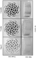
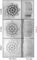
- biocarriers For all conditions, i.e. different types of biocarriers, the inoculum of microorganisms from previously colonized biocarriers was added and domestic gray water (from laundry) was added. Water was changed every 2 weeks and biomass growth on the new biocarriers was monitored. Incubation was carried out after 3 months under conditions of constant aeration and weekly water change. Biomass evaluation was performed after 5 weeks and 3 months, by macroscopic visualization, fresh/dry biomass estimation (analytical balance), bacterial density estimation (sonication and optical density at 600 nm) and metabolic activity estimation (MTT test).
- the new versions present better growth compared to the K3-PLA geometry.
- the new V1 design presented better colonization than K3-PETG.
- the addition of the vanes probably provided new biomass attachment points that allow the initation of colonization in the context of aeration, movement and constant agitation of the biocarriers within the biofilter submerged in gray water.
- the new V1 and V2 designs have larger surface area than the K3 design, therefore for each unit of biocarrier there is more surface area available for the settlement and growth of the microorganisms.
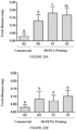
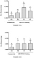
- the amount of biomass was determined on a high-precision analytical scale.
- the microorganisms were separated from the biocarriers using sonication, vortexing and centrifugation.
- the weight of the pellet of fresh microorganisms and the pellet of microorganisms dried for 48 hours at 65°C were measured.
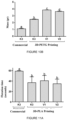
- the results in figure 20A show a significant increase in the amount of fresh biomass when using PLA in any geometry, with respect to the commercial K3 Biocarrier (HDPE), i.e. the PLA material has a positive effect on the fresh weight of biomass. Additionally, significantly higher fresh biomass is obtained for V1 compared to K3 PLA, i.e. the change of geometry also has a positive effect on this parameter.
- PETG as shown in figure 20B , the fresh biomass was significantly higher in all geometries compared to commercial K3.
- the dry biomass of the PLA biocarriers as shown in figure 21A , the new geometries V1 and V2 obtain higher biomass with respect to the commercial K3 Biocarrier (HDPE), but not K3 PLA.
- FIG. 22A shows a higher density of microorganisms in the V1 and V2 biocarriers with respect to the K3-PLA biocarrier and, in turn, to commercial K3, thus obtaining an improvement due to the material (PLA) and the new geometry of the V1 and V2 biocarriers.
- figure 22B shows a higher bacterial density of the three biocarriers in PETG with respect to the commercial biocarrier K3, thus obtaining an improvement due to the new material; however, the results obtained do not represent significant differences when using different biocarrier geometries.
- FIG. 23A shows a higher activity in the biocarriers V1 and V2 in PLA material, with respect to the commercial K3 biocarrier and K3-PLA, where the K3 biocarrier manufactured in PLA has no significant difference in metabolic activity with respect to the commercial K3 biocarrier.
- V1 PLA has a significant improvement in metabolic activity over V2 PLA, which would indicate that the very geometry of V1 promotes a higher metabolic rate of the biocarrier.
- Figure 23B reveals that the K3-PETG biocarrier has no significant difference in activity compared to its commercial K3-HDPE version, while the new V2 and V1 geometries present a significant increase in activity compared to commercial K3-HDPE. In this way, a better metabolic activity is obtained due to the new geometry of the V1 and V2 biocarriers with respect to the commercial biocarrier, and a higher metabolic activity of the V2 geometry compared to K3 printed on PLA and PETG.
- the V1 geometry manufactured in PLA improves the functionality of the biocarrier, thus revealing a higher fresh biomass, dry biomass, bacterial density and metabolic activity compared to the K3 geometry manufactured in PLA. Therefore, when comparing different geometries with the same material, it is proven that the V1 geometry by itself enhances biomass growth, thus improving the functionality of the biocarrier regardless of the effect of the material.
- both designs V1 and V2 of biocarriers allow a significant increase in the growth of biomass of microorganisms with respect to the commercial K3 geometry, evaluated through images, fresh and dry weight, and bacterial density, which in turn has a higher metabolic activity that can favor the water filtration process.
- COD removal was quantified with respect to day zero, as a measure of the organic matter contained in the water, which is shown in figures 25A and 25B .
- PLA biocarriers in all versions show a significant improvement in COD removal with respect to commercial K3. That is, there is a positive effect of the material in terms of organic matter removal.
- PETG biocarriers there was a significant increase in COD removal of the V2 PETG with respect to K3-HPDE and K3-PETG, indicating that the V2 geometry resulted in a positive effect on organic matter removal.
- water quality was measured in the field, using a 2000 liter purification system, which is comprised of a 1000 liter tank with the filtration & purification device inside (tank 1). A 1000 liter tank for post treatment of the water (tank 2), and a water pump, plus a chlorinator that pumps and chlorinates the water from tank 1 to tank 2. The water sample was taken after 14 hours of treatment, performed with the device according to the present invention. The results are shown in table 2.
- Table # 2 Water quality measurement results for a water purification system including the water filtration & purification device.
- Tank 1 Tank 2 Analysis method Law 21.075 Filtration & Purification device Post Treatment Urban use Turbidity (NTU) 2.7 5.5 *SM 2130 B Ed.23 5 DBO 5 (mg O 2 /L) 4 13 NCh2313/5 Of 2005 10 Fecal Coliforms (NMP/100ml) 23 ⁇ 2 NCh2313/23 Of 95 10 Suspended Solids (mg/L) 3 4 NCh2313/2. Of 95 10 Free residual chlorine (mg/L) ⁇ 0.02 6.66 ISO 7393/2 Of 2017 0.5 ⁇ X ⁇ 2
Landscapes
- Life Sciences & Earth Sciences (AREA)
- Chemical & Material Sciences (AREA)
- Biodiversity & Conservation Biology (AREA)
- Microbiology (AREA)
- Hydrology & Water Resources (AREA)
- Engineering & Computer Science (AREA)
- Environmental & Geological Engineering (AREA)
- Water Supply & Treatment (AREA)
- Organic Chemistry (AREA)
- Chemical Kinetics & Catalysis (AREA)
- General Chemical & Material Sciences (AREA)
- Biological Treatment Of Waste Water (AREA)
Applications Claiming Priority (1)
| Application Number | Priority Date | Filing Date | Title |
|---|---|---|---|
| PCT/CL2022/050078 WO2024026577A1 (es) | 2022-08-02 | 2022-08-02 | Dispositivo para la filtración y purificación de agua grises u otras aguas residuales para generar una nueva fuente hídrica limpia y segura mediante un filtro de tipo biológico |
Publications (2)
| Publication Number | Publication Date |
|---|---|
| EP4567005A1 true EP4567005A1 (de) | 2025-06-11 |
| EP4567005A4 EP4567005A4 (de) | 2026-01-07 |
Family
ID=89848204
Family Applications (1)
| Application Number | Title | Priority Date | Filing Date |
|---|---|---|---|
| EP22953395.5A Pending EP4567005A4 (de) | 2022-08-02 | 2022-08-02 | Vorrichtung zum filtern und reinigen von grauwasser oder anderem abwasser zur erzeugung einer neuen, sauberen und sicheren wasserquelle mittels eines biologischen filters |
Country Status (5)
| Country | Link |
|---|---|
| US (1) | US20250353763A1 (de) |
| EP (1) | EP4567005A4 (de) |
| CN (1) | CN119836402A (de) |
| AU (1) | AU2022472701A1 (de) |
| WO (1) | WO2024026577A1 (de) |
Family Cites Families (21)
| Publication number | Priority date | Publication date | Assignee | Title |
|---|---|---|---|---|
| US3956128A (en) * | 1973-07-16 | 1976-05-11 | Degremont, S.A. | Apparatus for treating industrial and domestic waste waters |
| FI54594C (fi) | 1977-09-02 | 1979-01-10 | Asko Upo Oy | Kombination av biologisk torrtoalett och biologisk rengoerinsanlaeggning foer avloppsvatten |
| JPH11226588A (ja) * | 1998-02-16 | 1999-08-24 | Katsumi Iida | 水処理用微生物担体要素 |
| JP2001327986A (ja) * | 2000-05-23 | 2001-11-27 | Hitachi Chem Co Ltd | 微生物担体およびそれを槽内に備えた浄化槽 |
| ITPD20030055A1 (it) * | 2003-03-18 | 2004-09-19 | Acqua Minerale S Benedetto S P A | Supporto per biofilm da utilizzare in impianti di purificazione |
| GB2403217B (en) * | 2003-06-18 | 2006-07-12 | Kingspan Holdings | A waste treatment system |
| US20070102354A1 (en) | 2005-10-26 | 2007-05-10 | Flournoy Wayne J | System for treating wastewater and a media usable therein |
| JP4700541B2 (ja) * | 2006-03-29 | 2011-06-15 | 株式会社クボタ | 微生物担持体及び浄化槽 |
| US20110036760A1 (en) | 2008-03-19 | 2011-02-17 | Hbio Reto Xxi S.L. | Grey water regeneration system |
| EP2119499A1 (de) * | 2008-04-28 | 2009-11-18 | Dytras, S.A. | Biofilmträger für die Verwendung in der Abwasserreinigung |
| CN103228577A (zh) * | 2010-08-06 | 2013-07-31 | 新加坡吉宝西格斯工程有限公司 | 废水处理装置和系统 |
| CA2779705C (en) | 2012-06-06 | 2020-08-11 | Canplas Industries Ltd. | System and method of greywater recovery and reuse |
| WO2014125496A1 (en) * | 2013-02-18 | 2014-08-21 | Mapal Green Energy Ltd. | Aerated bed biofilm reactor |
| US10196597B2 (en) * | 2014-03-11 | 2019-02-05 | Aqwise-Wise Water Technologies Ltd | Biomass carrier and a method of manufacturing thereof |
| ES1109280Y (es) * | 2014-04-29 | 2014-08-05 | Biolog Y Filtracion S L | Elemento portador de biomasa para sistemas de tratamiento biologico. |
| CN203999156U (zh) * | 2014-07-10 | 2014-12-10 | 上海埃格环保科技有限公司 | 一种利用微生物进行污水净化的水处理装置 |
| CN104843855B (zh) * | 2015-05-21 | 2017-06-20 | 浙江德安科技股份有限公司 | 一种生物填料结构 |
| DE202015103162U1 (de) * | 2015-06-16 | 2015-06-29 | MH Wassertechnologie GmbH | Anordnung für Trägermaterialkörper zur Abwasserreinigung |
| CN105366799B (zh) * | 2015-12-11 | 2018-06-12 | 山东大学 | 一种网箱式生物填料污水处理装置及其工作方法与应用 |
| SE543681C2 (en) * | 2019-10-18 | 2021-06-01 | Baga Water Tech Ab | Waste water treatment system |
| CN211971879U (zh) * | 2019-12-31 | 2020-11-20 | 上海伟辕环保科技有限公司 | 一种适用于污水处理的缓释填料 |
-
2022
- 2022-08-02 EP EP22953395.5A patent/EP4567005A4/de active Pending
- 2022-08-02 AU AU2022472701A patent/AU2022472701A1/en active Pending
- 2022-08-02 CN CN202280098798.0A patent/CN119836402A/zh active Pending
- 2022-08-02 US US19/100,836 patent/US20250353763A1/en active Pending
- 2022-08-02 WO PCT/CL2022/050078 patent/WO2024026577A1/es not_active Ceased
Also Published As
| Publication number | Publication date |
|---|---|
| AU2022472701A2 (en) | 2025-02-27 |
| CN119836402A (zh) | 2025-04-15 |
| WO2024026577A1 (es) | 2024-02-08 |
| EP4567005A4 (de) | 2026-01-07 |
| US20250353763A1 (en) | 2025-11-20 |
| AU2022472701A1 (en) | 2025-02-20 |
Similar Documents
| Publication | Publication Date | Title |
|---|---|---|
| ES2872525T3 (es) | Medio de biopelícula, sistema de tratamiento y método de tratamiento | |
| KR101782736B1 (ko) | 집약적 순환 여과식 양식시스템 | |
| CA2629910C (en) | Sewage treatment | |
| JP2000312542A (ja) | 魚介類の循環濾過養殖装置 | |
| CN101402487A (zh) | 一种两级移动床生物膜反应器中水处理系统 | |
| CN101643297B (zh) | 一种水产养殖循环水处理系统 | |
| WO2012036408A2 (ko) | 부하변동에 대응이 용이한 침지식 막 생물 반응장치 및 이를 이용한 하수처리 방법 | |
| US20250353763A1 (en) | Device for filtering and purifying greywater or other wastewater to generate a new, clean and safe water source by means of a biological filter | |
| CN111547962A (zh) | 一种处理粪尿的净化槽 | |
| WO2014142638A1 (en) | Water processing system | |
| CN111138029A (zh) | 一种分散式农村污水处理装置 | |
| KR20030013491A (ko) | 바이오 볼 및 바이오 탱크와 락 필터를 이용한 수처리장치 | |
| JP3263267B2 (ja) | 浄化槽 | |
| CN115888378B (zh) | 一种低耗高效的猪场微生物除臭系统及方法 | |
| CN205773889U (zh) | 一种化验室废液处理设备 | |
| CN201932948U (zh) | 一种高抗污染的mbr膜组件 | |
| CN209259873U (zh) | 一种高效小型污水净化系统 | |
| KR200324896Y1 (ko) | 수질정화용 생물막 유동상 담체 | |
| AU2006315091B2 (en) | Sewage treatment | |
| CN105936567A (zh) | 一种ombr一体化污水处理回用装置 | |
| CN205635253U (zh) | 一种智能污水处理系统 | |
| CN219907317U (zh) | 一种物化法医疗污水处理系统 | |
| CN205773925U (zh) | 一种渗透膜技术污水处理系统 | |
| JP2004122080A (ja) | 各室が所定の容積比の汚水浄化槽 | |
| CN220201681U (zh) | 公共泳池水消毒循环回用系统 |
Legal Events
| Date | Code | Title | Description |
|---|---|---|---|
| STAA | Information on the status of an ep patent application or granted ep patent |
Free format text: STATUS: THE INTERNATIONAL PUBLICATION HAS BEEN MADE |
|
| PUAI | Public reference made under article 153(3) epc to a published international application that has entered the european phase |
Free format text: ORIGINAL CODE: 0009012 |
|
| STAA | Information on the status of an ep patent application or granted ep patent |
Free format text: STATUS: REQUEST FOR EXAMINATION WAS MADE |
|
| 17P | Request for examination filed |
Effective date: 20250213 |
|
| AK | Designated contracting states |
Kind code of ref document: A1 Designated state(s): AL AT BE BG CH CY CZ DE DK EE ES FI FR GB GR HR HU IE IS IT LI LT LU LV MC MK MT NL NO PL PT RO RS SE SI SK SM TR |
|
| DAV | Request for validation of the european patent (deleted) | ||
| DAX | Request for extension of the european patent (deleted) | ||
| REG | Reference to a national code |
Ref country code: DE Ref legal event code: R079 Free format text: PREVIOUS MAIN CLASS: C02F0003000000 Ipc: C02F0003100000 |
|
| A4 | Supplementary search report drawn up and despatched |
Effective date: 20251204 |
|
| RIC1 | Information provided on ipc code assigned before grant |
Ipc: C02F 3/10 20230101AFI20251128BHEP Ipc: C02F 3/06 20230101ALI20251128BHEP Ipc: B01J 19/30 20060101ALI20251128BHEP Ipc: C02F 3/20 20230101ALI20251128BHEP |