EP4567145A1 - Procédé de fabrication d'un joint soudé par points, et joint soudé par points - Google Patents
Procédé de fabrication d'un joint soudé par points, et joint soudé par points Download PDFInfo
- Publication number
- EP4567145A1 EP4567145A1 EP23850179.5A EP23850179A EP4567145A1 EP 4567145 A1 EP4567145 A1 EP 4567145A1 EP 23850179 A EP23850179 A EP 23850179A EP 4567145 A1 EP4567145 A1 EP 4567145A1
- Authority
- EP
- European Patent Office
- Prior art keywords
- energization
- post
- spot
- welding
- time
- Prior art date
- Legal status (The legal status is an assumption and is not a legal conclusion. Google has not performed a legal analysis and makes no representation as to the accuracy of the status listed.)
- Pending
Links
Images




Classifications
-
- C—CHEMISTRY; METALLURGY
- C22—METALLURGY; FERROUS OR NON-FERROUS ALLOYS; TREATMENT OF ALLOYS OR NON-FERROUS METALS
- C22C—ALLOYS
- C22C38/00—Ferrous alloys, e.g. steel alloys
- C22C38/18—Ferrous alloys, e.g. steel alloys containing chromium
- C22C38/40—Ferrous alloys, e.g. steel alloys containing chromium with nickel
- C22C38/58—Ferrous alloys, e.g. steel alloys containing chromium with nickel with more than 1.5% by weight of manganese
-
- B—PERFORMING OPERATIONS; TRANSPORTING
- B23—MACHINE TOOLS; METAL-WORKING NOT OTHERWISE PROVIDED FOR
- B23K—SOLDERING OR UNSOLDERING; WELDING; CLADDING OR PLATING BY SOLDERING OR WELDING; CUTTING BY APPLYING HEAT LOCALLY, e.g. FLAME CUTTING; WORKING BY LASER BEAM
- B23K11/00—Resistance welding; Severing by resistance heating
- B23K11/10—Spot welding; Stitch welding
- B23K11/11—Spot welding
- B23K11/115—Spot welding by means of two electrodes placed opposite one another on both sides of the welded parts
-
- B—PERFORMING OPERATIONS; TRANSPORTING
- B23—MACHINE TOOLS; METAL-WORKING NOT OTHERWISE PROVIDED FOR
- B23K—SOLDERING OR UNSOLDERING; WELDING; CLADDING OR PLATING BY SOLDERING OR WELDING; CUTTING BY APPLYING HEAT LOCALLY, e.g. FLAME CUTTING; WORKING BY LASER BEAM
- B23K11/00—Resistance welding; Severing by resistance heating
- B23K11/16—Resistance welding; Severing by resistance heating taking account of the properties of the material to be welded
-
- C—CHEMISTRY; METALLURGY
- C22—METALLURGY; FERROUS OR NON-FERROUS ALLOYS; TREATMENT OF ALLOYS OR NON-FERROUS METALS
- C22C—ALLOYS
- C22C38/00—Ferrous alloys, e.g. steel alloys
- C22C38/02—Ferrous alloys, e.g. steel alloys containing silicon
-
- C—CHEMISTRY; METALLURGY
- C22—METALLURGY; FERROUS OR NON-FERROUS ALLOYS; TREATMENT OF ALLOYS OR NON-FERROUS METALS
- C22C—ALLOYS
- C22C38/00—Ferrous alloys, e.g. steel alloys
- C22C38/04—Ferrous alloys, e.g. steel alloys containing manganese
-
- C—CHEMISTRY; METALLURGY
- C22—METALLURGY; FERROUS OR NON-FERROUS ALLOYS; TREATMENT OF ALLOYS OR NON-FERROUS METALS
- C22C—ALLOYS
- C22C38/00—Ferrous alloys, e.g. steel alloys
- C22C38/06—Ferrous alloys, e.g. steel alloys containing aluminium
-
- C—CHEMISTRY; METALLURGY
- C22—METALLURGY; FERROUS OR NON-FERROUS ALLOYS; TREATMENT OF ALLOYS OR NON-FERROUS METALS
- C22C—ALLOYS
- C22C38/00—Ferrous alloys, e.g. steel alloys
- C22C38/12—Ferrous alloys, e.g. steel alloys containing tungsten, tantalum, molybdenum, vanadium, or niobium
-
- C—CHEMISTRY; METALLURGY
- C22—METALLURGY; FERROUS OR NON-FERROUS ALLOYS; TREATMENT OF ALLOYS OR NON-FERROUS METALS
- C22C—ALLOYS
- C22C38/00—Ferrous alloys, e.g. steel alloys
- C22C38/14—Ferrous alloys, e.g. steel alloys containing titanium or zirconium
-
- C—CHEMISTRY; METALLURGY
- C22—METALLURGY; FERROUS OR NON-FERROUS ALLOYS; TREATMENT OF ALLOYS OR NON-FERROUS METALS
- C22C—ALLOYS
- C22C38/00—Ferrous alloys, e.g. steel alloys
- C22C38/18—Ferrous alloys, e.g. steel alloys containing chromium
- C22C38/20—Ferrous alloys, e.g. steel alloys containing chromium with copper
-
- C—CHEMISTRY; METALLURGY
- C22—METALLURGY; FERROUS OR NON-FERROUS ALLOYS; TREATMENT OF ALLOYS OR NON-FERROUS METALS
- C22C—ALLOYS
- C22C38/00—Ferrous alloys, e.g. steel alloys
- C22C38/18—Ferrous alloys, e.g. steel alloys containing chromium
- C22C38/22—Ferrous alloys, e.g. steel alloys containing chromium with molybdenum or tungsten
-
- C—CHEMISTRY; METALLURGY
- C22—METALLURGY; FERROUS OR NON-FERROUS ALLOYS; TREATMENT OF ALLOYS OR NON-FERROUS METALS
- C22C—ALLOYS
- C22C38/00—Ferrous alloys, e.g. steel alloys
- C22C38/18—Ferrous alloys, e.g. steel alloys containing chromium
- C22C38/26—Ferrous alloys, e.g. steel alloys containing chromium with niobium or tantalum
-
- C—CHEMISTRY; METALLURGY
- C22—METALLURGY; FERROUS OR NON-FERROUS ALLOYS; TREATMENT OF ALLOYS OR NON-FERROUS METALS
- C22C—ALLOYS
- C22C38/00—Ferrous alloys, e.g. steel alloys
- C22C38/18—Ferrous alloys, e.g. steel alloys containing chromium
- C22C38/28—Ferrous alloys, e.g. steel alloys containing chromium with titanium or zirconium
-
- C—CHEMISTRY; METALLURGY
- C22—METALLURGY; FERROUS OR NON-FERROUS ALLOYS; TREATMENT OF ALLOYS OR NON-FERROUS METALS
- C22C—ALLOYS
- C22C38/00—Ferrous alloys, e.g. steel alloys
- C22C38/18—Ferrous alloys, e.g. steel alloys containing chromium
- C22C38/32—Ferrous alloys, e.g. steel alloys containing chromium with boron
-
- C—CHEMISTRY; METALLURGY
- C22—METALLURGY; FERROUS OR NON-FERROUS ALLOYS; TREATMENT OF ALLOYS OR NON-FERROUS METALS
- C22C—ALLOYS
- C22C38/00—Ferrous alloys, e.g. steel alloys
- C22C38/18—Ferrous alloys, e.g. steel alloys containing chromium
- C22C38/34—Ferrous alloys, e.g. steel alloys containing chromium with more than 1.5% by weight of silicon
-
- C—CHEMISTRY; METALLURGY
- C22—METALLURGY; FERROUS OR NON-FERROUS ALLOYS; TREATMENT OF ALLOYS OR NON-FERROUS METALS
- C22C—ALLOYS
- C22C38/00—Ferrous alloys, e.g. steel alloys
- C22C38/18—Ferrous alloys, e.g. steel alloys containing chromium
- C22C38/38—Ferrous alloys, e.g. steel alloys containing chromium with more than 1.5% by weight of manganese
-
- C—CHEMISTRY; METALLURGY
- C22—METALLURGY; FERROUS OR NON-FERROUS ALLOYS; TREATMENT OF ALLOYS OR NON-FERROUS METALS
- C22C—ALLOYS
- C22C38/00—Ferrous alloys, e.g. steel alloys
- C22C38/18—Ferrous alloys, e.g. steel alloys containing chromium
- C22C38/40—Ferrous alloys, e.g. steel alloys containing chromium with nickel
- C22C38/42—Ferrous alloys, e.g. steel alloys containing chromium with nickel with copper
-
- C—CHEMISTRY; METALLURGY
- C22—METALLURGY; FERROUS OR NON-FERROUS ALLOYS; TREATMENT OF ALLOYS OR NON-FERROUS METALS
- C22C—ALLOYS
- C22C38/00—Ferrous alloys, e.g. steel alloys
- C22C38/18—Ferrous alloys, e.g. steel alloys containing chromium
- C22C38/40—Ferrous alloys, e.g. steel alloys containing chromium with nickel
- C22C38/44—Ferrous alloys, e.g. steel alloys containing chromium with nickel with molybdenum or tungsten
-
- C—CHEMISTRY; METALLURGY
- C22—METALLURGY; FERROUS OR NON-FERROUS ALLOYS; TREATMENT OF ALLOYS OR NON-FERROUS METALS
- C22C—ALLOYS
- C22C38/00—Ferrous alloys, e.g. steel alloys
- C22C38/18—Ferrous alloys, e.g. steel alloys containing chromium
- C22C38/40—Ferrous alloys, e.g. steel alloys containing chromium with nickel
- C22C38/46—Ferrous alloys, e.g. steel alloys containing chromium with nickel with vanadium
-
- C—CHEMISTRY; METALLURGY
- C22—METALLURGY; FERROUS OR NON-FERROUS ALLOYS; TREATMENT OF ALLOYS OR NON-FERROUS METALS
- C22C—ALLOYS
- C22C38/00—Ferrous alloys, e.g. steel alloys
- C22C38/18—Ferrous alloys, e.g. steel alloys containing chromium
- C22C38/40—Ferrous alloys, e.g. steel alloys containing chromium with nickel
- C22C38/48—Ferrous alloys, e.g. steel alloys containing chromium with nickel with niobium or tantalum
-
- C—CHEMISTRY; METALLURGY
- C22—METALLURGY; FERROUS OR NON-FERROUS ALLOYS; TREATMENT OF ALLOYS OR NON-FERROUS METALS
- C22C—ALLOYS
- C22C38/00—Ferrous alloys, e.g. steel alloys
- C22C38/18—Ferrous alloys, e.g. steel alloys containing chromium
- C22C38/40—Ferrous alloys, e.g. steel alloys containing chromium with nickel
- C22C38/50—Ferrous alloys, e.g. steel alloys containing chromium with nickel with titanium or zirconium
-
- C—CHEMISTRY; METALLURGY
- C22—METALLURGY; FERROUS OR NON-FERROUS ALLOYS; TREATMENT OF ALLOYS OR NON-FERROUS METALS
- C22C—ALLOYS
- C22C38/00—Ferrous alloys, e.g. steel alloys
- C22C38/18—Ferrous alloys, e.g. steel alloys containing chromium
- C22C38/40—Ferrous alloys, e.g. steel alloys containing chromium with nickel
- C22C38/54—Ferrous alloys, e.g. steel alloys containing chromium with nickel with boron
-
- B—PERFORMING OPERATIONS; TRANSPORTING
- B23—MACHINE TOOLS; METAL-WORKING NOT OTHERWISE PROVIDED FOR
- B23K—SOLDERING OR UNSOLDERING; WELDING; CLADDING OR PLATING BY SOLDERING OR WELDING; CUTTING BY APPLYING HEAT LOCALLY, e.g. FLAME CUTTING; WORKING BY LASER BEAM
- B23K2103/00—Materials to be soldered, welded or cut
- B23K2103/02—Iron or ferrous alloys
- B23K2103/04—Steel or steel alloys
Definitions
- the present disclosure relates to a method of producing a spot-welded joint and a spot-welded joint.
- Tensile strength is an important property for a joint formed by spot-welding a sheet combination of a plurality of steel sheets overlapped (sometimes referred to as “spot-welded joint” in the disclosure).
- the tensile strength of spot-welded joints includes tensile shear strength (TSS) measured with a tensile load applied in the shear direction and cross tensile strength (hereinafter also referred to as "CTS” or “joint strength”) measured with a tensile load applied in the peeling direction.
- TSS tensile shear strength
- CTS cross tensile strength
- spot-welded joints including high-strength steel sheets, tend to have a low CTS, and there is a demand for improving the CTS.
- Patent Literature 1 discloses a resistance spot-welding method in which two or more overlapped high-strength thin steel sheets are clamped with a pair of electrodes, and a current is applied thereto under a pressurizing force so as to form a weld zone, the method including: a first step of performing energization at a welding current (Im) to form a nugget; a second step of performing energization on the weld zone at a current value not more than the welding current (Im); a third step of cooling the weld zone; and a fourth step of performing energization on the weld zone at a current value more than the welding current (Im) to heat the weld zone to a recrystallization temperature range in that order.
- a welding current Im
- Patent Literature 2 discloses a resistance spot-welding method in which welding is carried out by performing energization on a sheet combination of two or more overlapped steel sheets with a total sheet thickness t (mm), which is clamped with a pair of welding electrodes under pressurization, the method including a first step of forming a nugget; and a second step of maintaining a weld zone with no-energization while applying pressure with the electrodes for cooling, followed by energization, in which the energization time TA (ms) and the energization current IA (kA) in the first step and the energization time TB (ms) and the energization current IB (kA) in the second step satisfy Formulas (1) and (2), the energization current IB (kA) is higher than the energization current IA(kA), and the holding time Th (ms) for no-energization in the second step satisfies Formula (3) in relation
- Patent Literature 3 discloses a spot-welding method for improving cross tensile strength of a spot-welded joint, the method including the following steps of: forming a fusion zone by overlapping a plurality of steel sheets including a high-strength steel sheet having a tensile strength of from 750 to 2500 MPa and a predetermined carbon equivalent Ceq of from 0.20% to 0.55% by mass and by main welding; performing a first cooling/post-energization during which energization is paused, the steel sheets are cooled to form a solidified area in the fusion zone, and then sequentially post-energization is performed to prevent re-fusion of the solidified area; and then after the termination of the step of performing the first cooling/post-energization, carrying out once or more a step of performing cooling/post-energization by pausing energization for cooling time t S (ms) to satisfy predetermined conditions while maintaining a predetermined pressurizing force F E (N), and then
- Patent Literature 4 to 6 also disclose a spot-welding method in which post-energization is performed after main energization.
- An object of the disclosure is to provide a method of producing a spot-welded joint, by which the cross tensile strength of a joint can be effectively improved using a high-strength steel sheet, compared with a method of producing a spot-welded joint by performing post-energization once after main welding, and such a spot-welded joint.
- the gist of the present disclosure to achieve the above object is as follows.
- a method of producing a spot-welded joint by which the cross tensile strength of a joint can be effectively improved, compared with a method of producing a spot-welded joint by performing post-energization once after main welding, and such a spot-welded joint, can be provided.
- the "%” sign for the content of each element means “% by mass.”
- a numerical range expressed using “to” means a range including the numerical values before and after “to” as the lower and upper limits in the disclosure. In a case in which the numerical range described before and after “to” is followed by “more than” or “less than,” it means that the numerical range does not include the numerical value as the lower limit or upper limit.
- the upper limit value of one stepwise numerical range may be replaced by the upper limit value of another stepwise numerical range, or may be replaced by a value shown in the Examples.
- the lower limit value of one stepwise numerical range may be replaced by the lower limit value of another stepwise numerical range, or may be replaced by a value shown in the Examples.
- step includes not only an independent step but also a step that cannot be clearly distinguished from other steps as long as the intended purpose of the step is achieved.
- the inventors of the disclosure made intensive studies on a method of effectively improving joint strength for producing a spot-welded joint by spot-welding a sheet combination including a high-strength steel sheet having a tensile strength of, for example, 900 MPa or more.
- the inventors found that the joint strength can be effectively improved by performing post-energization for a plurality of times (at least two times) after main welding under pressurization at a predetermined pressurizing force F E (N) corresponding to the sheet thickness of the high-strength steel sheet, during which the current value is set to be smaller than that of main welding in the first post-energization, and the second post-energization is performed with a current value and an energization time that satisfies a predetermined relationship with the immediately preceding cooling time and the current value of main welding.
- a sheet combination of a plurality of overlapped steel sheets including at least one high-strength steel sheet having a carbon equivalent "Ceq" described later of 0.36% by mass or more (sometimes simply referred to as "high-strength steel sheet” in the disclosure) is used in the method of producing a spot-welded joint according to the disclosure.
- the plurality of steel sheets constituting the sheet combination may each be a high-strength steel sheet having a carbon equivalent Ceq of 0.36% by mass or more.
- at least one of them may be a high-strength steel sheet having a carbon equivalent Ceq of 0.36% by mass or more and at least another one of them may be a steel sheet having a carbon equivalent Ceq of less than 0.36% by mass.
- at least one of the steel sheets need only be a high-strength steel sheet, and one or more steel sheets having a carbon equivalent Ceq of less than 0.36% by mass may be included.
- the plurality of steel sheets constituting the sheet combination in the disclosure may be, but are not limited to flat steel sheets, steel sheets processed by hot stamping (hot press) or the like.
- the sheet combination may be made by overlapping a plurality of steel sheets processed into a three-dimensional part shape by bending or the like or may be made by overlapping a flat steel sheet and a steel sheet processed into the part shape.
- the flat portion (sheet-shaped portion) on which spot-welding is performed corresponds to the "steel sheet" in the disclosure.
- the tensile strength of the high-strength steel sheet is preferably 900 MPa or more, and there is no particular upper limit. However, when the tensile strength is excessively high, defects and cracks are more likely to occur inside a nugget. Therefore, the tensile strength of the high-strength steel sheet is preferably 2500 MPa or less.
- the tensile strength (TS) of a steel sheet may be measured by sampling a JIS No. 5 tensile test piece (gage length: 50 mm; width 25 mm) from the steel sheet and pulling a sample at a tensile speed of 10 mm/min in accordance with ISZ 2241:2011.
- TS may be measured using a JIS No. 13B (gage length: 50 mm; width: 12.5 mm).
- the high-strength steel sheet in the disclosure has a carbon equivalent Ceq represented by the following Formula (A) of 0.36% by mass or more.
- Ceq C + Si / 30 + Mn / 20 + 2 P + 4 S
- [C], [Si], [Mn], [P], and [S] are the contents (% by mass) of C, Si, Mn, P, and S contained in the high-strength steel sheet, respectively.
- the tensile strength of the high-strength steel sheet can be, for example, 900 MPa or more.
- the upper limit of carbon equivalent Ceq is not particularly limited. For example, when it exceeds 0.55% by mass, a high-strength steel sheet having a tensile strength exceeding 2500 MPa can be obtained. On the other hand, it is difficult to improve the CTS of a spot-welded joint. Therefore, the Ceq of the high-strength steel sheet is preferably 0.55% by mass or less.
- the Ceq of the steel sheet is not particularly limited and thus may be less than 0.36% by mass.
- the analysis of the chemical composition of the steel sheet may be carried out by any chemical analysis method known to those skilled in the art, for example, inductively coupled plasma mass spectrometry (ICP-MS method).
- ICP-MS method inductively coupled plasma mass spectrometry
- C and S may be measured using the combustion-infrared absorption method
- N may be measured using the inert gas fusionthermal conductivity method.
- the high-strength steel sheet in the disclosure may have a chemical composition that results in a carbon equivalent Ceq of 0.36% by mass or more.
- a preferred chemical composition of the high-strength steel sheet in the disclosure will be described.
- the C is an element that increases the tensile strength of steel.
- the C content in the steel is 0.07% or more, a tensile strength of 900 MPa or more is easily obtained.
- the C content in the steel is 0.50% or less, the deterioration of the workability of the high-strength steel sheet can be suppressed. Therefore, the C content in the high-strength steel sheet is preferably from 0.07% to 0.50%.
- Si from 0.001% to 2.50%
- Si is an element that increases the strength of steel through solid-solution strengthening and structural strengthening.
- the Si content in the steel is 2.50% or more, deterioration in the workability of the steel can be suppressed.
- the Si content in the steel is 0.001% or more, it facilitates the manufacturing industrially or technically. Therefore, the Si content in the high-strength steel sheet is preferably from 0.001% to 2.50%.
- Mn is an element that increases the strength of steel.
- the Mn content in the steel is 5.0% or less, deterioration in the workability of the steel can be suppressed. Meanwhile, when the Mn content in the steel is 0.8% or more, a tensile strength of 900 MPa or more is easily obtained. Therefore, the Mn content in the high-strength steel sheet is preferably 0.8% to 5.0%.
- the P content in the high-strength steel sheet is preferably 0.03% or less.
- the P content in the high-strength steel sheet may be 0.001% or more.
- S is an element that embrittles a nugget.
- S is an element that binds to Mn to form coarse MnS, which impairs the workability of steel.
- the S content in steel is 0.01% or less, cracks are less likely to occur in the nugget, and sufficiently high joint strength is likely to be obtained.
- the workability of the steel is improved. Therefore, the S content in the high-strength steel sheet is preferably 0.01% or less. From the viewpoint of suppressing an increase in the production cost, the S content in the high-strength steel sheet may be 0.0001% or more.
- N is an element that forms a coarse nitride and deteriorates the workability of steel. N is also an element that can cause blowholes during welding. To suppress deterioration of the workability of the steel and the occurrence of blowholes, the N content in the high-strength steel sheet is preferably 0.01% or less. From the viewpoint of suppressing an increase in the production cost, the N content in the high-strength steel sheet may be 0.0005% or more.
- the O content in the high-strength steel sheet is preferably 0.01% or less. From the viewpoint of suppressing an increase in the production cost, the O content in the high-strength steel sheet may be 0.0005% or more.
- Al is a ferrite-stabilizing element and has the effect of suppressing cementite precipitation during bainite transformation. For this reason, Al is contained to control the steel structure. Al also functions as a deoxidizer. Meanwhile, Al is easily oxidized, and the increase in inclusions leads to a deterioration in the workability of the steel. Therefore, the Al content in the high-strength steel sheet is preferably 1.50% or less.
- the high-strength steel sheet may selectively contain the following elements, if necessary.
- Ti, Nb, V from 0.005% to 0.20%
- Ti, Nb, and V are elements that contribute to increasing the strength of steel by at least one of precipitation strengthening, fine grain strengthening by suppressing the growth of ferrite crystal grains, and dislocation strengthening by suppressing recrystallization.
- the content of any of these elements in the steel is less than 0.005%, the effect of including these elements is unlikely to be exhibited.
- the content in the steel is 0.20% or less, the impairment of the workability of the steel can be suppressed. Therefore, the content of any of these elements in the high-strength steel sheet is preferably from 0.005% to 0.20%.
- the B is an element that controls the steel structure and strengthens steel.
- the B content in the steel is less than 0.0001%, the effect of including B is unlikely to be exhibited.
- the content of B in the steel exceeds 0.01%, the effect of including B is saturated. Therefore, the B content in the high-strength steel sheet is preferably from 0.0001% to 0.01%.
- Cr, Ni, Cu, and Mo are elements that contribute to improving the strength of steel. These elements can be used, for example, to replace part of Mn (a strength-improving element). However, any of these elements is likely to contribute to improving strength as long as its content in the steel is 0.01% or more.
- the content of any of these elements in the high-strength steel sheet is preferably 0.01% or more.
- the contents of Cr, Ni, and Cu in the steel are 2.0% or less, problems occurring during pickling or hot working can be suppressed when the Mo content in the steel exceeds 0.8%. Therefore, the Cr, Ni, and Cu contents in the high-strength steel sheet are preferably 2.0% or less.
- the Mo content in the high-strength steel sheet is preferably 0.8% or less.
- At least one kind of Ca, Mg, or REM from 0.0001% to 1.0% in total
- Ca, Mg, and a rare earth metal (REM) are elements that reduce the size of an oxide after deoxidation and the size of a sulfide present in a hot-rolled steel sheet, thereby contributing to improving the workability of steel.
- the total content of these elements in the steel is 0.0001% or more, the effect of including them is easily exhibited. Meanwhile, when the total content of these elements in the steel is 1.0% or less, deterioration in the workability of the steel is suppressed. Therefore, the total content of these elements in the high-strength steel sheet is preferably from 0.0001% to 1.0%.
- REM is a general term for 17 elements in total, including Sc, Y, and 15 elements belonging to the lanthanide series. REM can be added to molten steel as a misch metal during steelmaking. In addition, the lanthanide series elements may be contained in a composite form.
- the balance other than the above elements in the high-strength steel sheet is Fe and impurities.
- Impurities include, for example, components contained in raw materials such as ores and scraps, or components mixed in during the production process, and refer to components that are not purposely contained in the steel sheet.
- Each of the above-described Cr, Ni, Cu, Mo, B, Ti, Ni, and V is permitted to be contained as an impurity in a trace amount less than the lower limit value.
- Ca, Ce, Mg, La, and REM are also permitted to be contained as impurities in trace amounts less than the lower limit value of the total amount thereof.
- the chemical composition of the high-strength steel sheet in the disclosure has been described above. However, in a case in which a steel sheet having a carbon equivalent Ceq of less than 0.36% by mass is included as a steel sheet constituting a sheet combination, the chemical composition and tensile strength of the steel sheet are not particularly limited.
- the steel structure (steel type) of the high-strength steel sheet is not particularly limited as long as the carbon equivalent Ceq is 0.36% by mass or more.
- it may be any type of structure (steel type), such as two-phase structure type (e.g., a structure containing martensite in ferrite or a structure containing bainite in ferrite), processing-induced transformation type (a structure containing retained austenite in ferrite), quenching type (martensite structure), or fine crystal structure type (a structure containing mainly ferrite).
- the steel structure (steel type) of the steel sheet is not particularly limited.
- the sheet thickness of the high-strength steel sheet in the disclosure is not particularly limited.
- the sheet thickness may be approximately the same as that of high-strength steel sheets (0.5 mm to 3.2 mm) that are generally used for automobile bodies and the like. Note that since stress concentration around the nugget increases with an increase in the sheet thickness of the high-strength steel sheet, the sheet thickness of the high-strength steel sheet is preferably 2.6 mm or less.
- the sheet thickness of the steel sheet is not particularly limited.
- the sheet thicknesses of a plurality of steel sheets constituting a sheet combination may be the same or different from each other.
- the thicknesses of the steel sheets may be different from each other, or at least two of the steel sheets may have the same thickness.
- the steel sheets constituting the sheet combination may have a plating layer formed on the surface.
- Examples of the types of plating layers include Zn-based, Zn-Fe-based, Zn-Ni-based, Zn-Al-based, Zn-Mg-based, Pb-Sn-based, Sn-Zn-based, and Al-Si-based plating layers.
- the plating layer may be a single layer or multiple plating layers.
- Examples of a steel sheet having a Zn-based plating layer include alloyed hot-dip galvanized steel sheets, hot-dip galvanized steel sheets, and electrolytic galvanized steel sheets. As long as a plating layer is formed on the surface of the steel sheets of the sheet combination, the spot-welded joint after spot-welding exhibits excellent corrosion resistance. In a case in which the plating layer is a galvanized layer formed by alloying the surface of the steel sheet, excellent corrosion resistance is obtained, and the adhesion of paint becomes excellent.
- the coating amount of the plating layer is not particularly limited.
- the plating layer may be formed on only one side or on both sides of the steel sheet.
- An inorganic or organic coating e.g., a lubricating coating
- the main welding step of forming a fusion zone in a sheet combination in which a plurality of steel sheets including at least one high-strength steel sheet described above are overlapped, is performed, and the post-energization step is performed at least two times after the main welding step sequentially on the sheet combination.
- spot-welding two overlapped steel sheets including at least one high-strength steel sheet described above will be described.
- Spot-welding can be performed by the same method described below also in the case of spot-welding three or more steel sheets including at least one high-strength steel sheet.
- Fig. 1 schematically illustrates an example of the arrangement of two steel sheets including at least one high-strength steel sheet and welding electrodes when starting spot-welding.
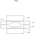
- Fig. 2 schematically illustrates an example of a nugget and a heat-affected zone (HAZ) formed by spot-welding.
- HZ heat-affected zone
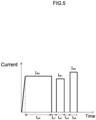
- Fig. 3 is a diagram illustrating an example of an energization pattern when energizing welding electrodes in the method of producing a spot-welded joint according to the disclosure.
- the current described below is a current flowing between welding electrodes 2A and 2B.
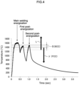
- Fig. 4 is a diagram illustrating a simulation of the temperature history of a weld zone in the method of producing a spot-welded joint according to the disclosure.
- QuickSpot Research Center of Computational Mechanics, Inc.
- a sheet combination in which steel sheets 1A and 1B are overlapped such that their sheet surfaces face each other is prepared and then clamped between a pair of welding electrodes 2A and 2B in the sheet thickness direction.
- the welding electrodes 2A and 2B are energized at a main welding current value I w0 (kA) under pressurization with a pressurizing force F E (N) that satisfies the following Formula (B), and main welding (main energization) for forming a fusion zone in the sheet combination is performed.
- At least one of the steel sheets 1A and 1B is the above-described high-strength steel sheet. 2000 ⁇ h ⁇ F E ⁇ 4500 ⁇ h
- h (mm) refers to the arithmetic mean value of sheet thicknesses of a plurality of overlapped steel sheets.
- the arithmetic mean value of the sheet thicknesses of two steel sheets (arithmetic mean value of sheet thicknesses of steel sheets 1A and 1B) is used as "h” in Formula (B).
- the sum of the sheet thicknesses of the plurality of steel sheets is calculated, and the sum is divided by the number of sheets in the sheet combination, and the resultant value is used as "h” in Formula (B).
- the arithmetic mean value h of the sheet thickness may be determined by measuring the thickness of each steel sheet and taking the arithmetic mean value thereof as h.
- the sheets In the case of measurement by overlapping steel sheets to be joined, it is necessary to measure without any gaps. Therefore, in a case in which there is any warping or floating, the sheets should be clamped or the like to measure, and the measurement result should be divided by the number of overlapped sheets to obtain h.
- the pressurizing force F E is less than "2000 ⁇ h" (N)
- the main welding current I w0 and the main welding energization time t w0 may be conditions that allow the formation of a fusion zone that will serve as a nugget for joining all steel sheets constituting a sheet combination.
- the welding current and the energization time comparable to the welding current and the energization time conventionally adopted for stably obtaining a nugget having a predetermined size can be adopted as the main welding current I w0 and the main welding time t w0 .
- the pressurizing force may be measured using the pressurizing force value displayed by the spot-welding machine in a case in which the machine is equipped with such a device or may be measured using a pressure gauge such as a quartz piezoelectric sensor attached to the transmission shaft so as to be equivalent to the pressurization load on the steel sheet.
- the current value can be measured using a current monitor called a weld checker or welding ammeter.
- the measurement method is not specified, but for example, a method may be used in which a toroidal coil is inserted into a circuit through which the current flows during welding and changes in the current value are read.
- the energization time t w0 in the main welding step can be from 10t' - 5 to 10t' + 50 cycles (the unit of time is the number of cycles at 50 Hz in the disclosure) or the like.
- nugget diameter 4 ⁇ t' or more where t' is the sheet thickness of the thin sheet at the interface between the sheets for the thickness of the sheet combination.
- the nugget diameter is more desirably 5 ⁇ t' or more.
- a gradual increase (upslope) of from 1 to 80 cycles (50 Hz) may be set before the main welding step.
- the current value at the end of the upslope energization is set to the current value I w0 (kA) in the main welding step, and the energization time t w0 (ms) in the main welding step does not include the time required for the upslope energization.
- the current value is increased upslope from 0 (zero) until it reaches the main welding current I w0 (kA).
- main welding is performed at the main welding current I w0 (kA).
- pre-energization Before the main welding step, pre-energization may be performed for, for example, from 2 to 80 cycles at a current value lower than that in the main welding step.
- This pre-energization may be a multi-stage energization, and a no-energization time may be provided in between.
- a fusion zone and a heat-affected zone (so-called HAZ) 14 that will become a nugget 13 at the end of spot-welding are formed in the energized portion between the steel sheets 1A and 1B.
- spot-welding equipment conventional general spot-welding equipment can be used as it is.
- welding electrodes or the like conventional welding electrodes can be used as they are.
- the power source is also not particularly limited, and an AC power source, a DC inverter, an AC inverter, or the like can be used.
- the tip diameters of the welding electrodes 2A and 2B are preferably about from 6 mm to 8 mm.
- energization is performed at a first post-energization current value I w1 (kA) that satisfies the following Formula (D) for time t w1 (ms) that satisfies the following Formula (E) following no-energization during which energization is paused for time t c1 (ms) that satisfies the following Formula (C) after the main welding step.
- I w1 KA
- Formula (D) for time t w1 (ms) that satisfies the following Formula (E) following no-energization during which energization is paused for time t c1 (ms) that satisfies the following Formula (C) after the main welding step.
- energization is performed with the welding electrodes 2A and 2B for a predetermined time at the main welding current I w0 such that a fusion zone is formed in the steel sheets 1A and 1B. Then, immediately after the main welding is terminated by setting the current value to 0 (zero), energization is paused for time t c1 (ms) that satisfies Formula (C) while maintaining the pressurizing force F E that was used during the main welding (during energization at the main welding current I w0 ). This causes the fusion zone formed by the main welding to solidify from the outer periphery of the fusion zone (i.e., the boundary of the fusion zone with other regions). In the disclosure, the boundary between the fusion zone and other regions is referred to as a "fusion boundary.”
- the no-energization time t c1 after the main welding step is less than 2 ms, there is a risk that the nugget end will not be solidified before the subsequent post-energization. Meanwhile, in a case in which the no-energization time t c1 exceeds 300 ms, there is a risk that the nugget end will be solidified excessively before the subsequent post-energization.
- the no-energization time t c1 after the main welding step is from 2 ms to 300 ms and preferably from 40 ms to 250 ms.
- the first post-energization step energization is performed at the first post-energization current value I w1 (kA) that satisfies Formula (D) for time t w1 (ms) that satisfies Formula (E) following no-energization during which energization is paused for time t c1 (ms) that satisfies Formula (C).
- the first post-energization current value I w1 is set to smaller than the main welding current value I w0 in the main welding step and more than 0.75 ⁇ I w0 at the same time, and the first post-energization time t w1 is set to more than 100 ms.
- At least part of the nugget is refused without crossing the fusion boundary created by the main welding step as illustrated in Fig. 4 such that the ⁇ phase (fcc crystal structure) formed in the nugget is transformed into a ⁇ phase (bcc crystal structure) by cooling during the no-energization time t c1 after the main welding step.
- the first post-energization time t w1 in the first post-energization step is set to preferably from 110 ms to 1000 ms and more preferably from 150 ms to 800 ms from the viewpoint of re-fusing the nugget and reducing the time required for spot-welding as a whole.
- the pressurizing force F E in the first post-energization step it is preferable to maintain the pressurizing force F E in the first post-energization step at the same value as the pressurizing force F E in the main welding step.
- the pressurizing force F E during the no-energization time t c1 may be set differently from the pressurizing force F E in the main welding step within the scope that satisfies Formula (B).
- the post-energization step is performed at least one time as the second or subsequent post-energization step after the first post-energization step.
- energization is performed at a second post-energization current value I w2 (kA) that satisfies the following Formula (G1) for second post-energization time t w2 (ms) following no-energization during which energization is paused for time t c2 (ms) that satisfies the following Formula (F1) after the first post-energization step.
- phase transformation due to each post-energization step and the location of the phase transformation can be determined by observing the cross section near the center of the nugget by EBSD as illustrated in Fig. 8 , and making the determination based on the fine grain regions of the crystal grains before and after each post-energization step.
- phase transformation is induced at appropriate positions by performing post-energization two or more times such that the conditions of the disclosure are satisfied, whereby, as described later, a nugget can be formed in which the proportion of grains having an aspect ratio of 7 or more in the vicinity of the center of the nugget is 50% or less.
- the no-energization time t c2 after the first post-energization step is less than 2 ms, there is a risk that the nugget end will not be solidified before the second post-energization step. Meanwhile, in a case in which the no-energization time t c2 exceeds 300 ms, there is a risk that the nugget end will be solidified excessively before the first post-energization step.
- the no-energization time t c2 after the first post-energization step is from 2 ms to 300 ms and preferably from 60 ms to 250 ms.
- the nugget is cooled during the no-energization time t c2 to become the ⁇ phase (fcc crystal structure).
- post-energization is performed under conditions that allow the second post-energization current value I w2 and the second post-energization time t w2 to satisfy Formula (G1) with respect to the main welding current value I w0 in the main welding step and the no-energization time t c2 in the second post-energization step such that the nugget is transformed again into a ⁇ phase (bcc crystal structure) as illustrated in Fig. 4 .
- This promotes equiaxed grain refinement in the nugget, allowing the CTS to improve.
- the current value I w2 in the second post-energization step is set to be greater than 0.75 ⁇ I w0 .
- Energization is performed such that the relationship between the main welding current value I w0 and the second post-energization current value I w2 (kA) satisfies the following Formula (H1). 0.75 ⁇ I w 0 ⁇ I w 2
- the relationship between the main welding current value I w0 and the second post-energization current value I w2 satisfies the following Formula (I). I w 2 > I w 0
- Fig. 5 illustrates an example of the energization pattern that satisfies Formula (I).
- the pressurizing force F E is maintained as is, during which energization is paused, and the post-energization step is terminated after the second time, the pressurizing force F E created by the welding electrodes 2A and 2B is released from the overlapped steel sheets 1A and 1B (sheet combination). It is preferable to provide a so-called holding time during which only pressurizing force is applied without energization after the second post-energization step. A holding time of 5 cycles (50 Hz) or more is desirable.
- the pressurizing force F E in the second post-energization step may be set differently from the pressurizing force F E in the main welding step within the scope that satisfies Formula (B).
- the pressurizing force F E may be constant or vary within a range that satisfies Formula (B) from the main welding step to the termination of the final post-energization step.
- a downslope may be set after the second post-energization step. Due to the downslope, it is possible to further improve the properties of the spot-weld zone by reducing cracks due to liquid metal embrittlement, reducing blowholes, and suppressing delayed fracture.
- the current value at the start of downslope energization is set to the second post-energization current value I w2 (kA) in the second post-energization step, and the second post-energization time t w2 (ms) in the second post-energization step does not include the time required for the downslope energization.
- CTS By performing resistance spot-welding consisting of the above-described steps on the sheet combination formed by overlapping a plurality of steel sheets including at least one high-strength steel sheet, CTS can be significantly improved, compared with the case of performing resistance spot-welding by single energization. According to the disclosure, it is possible to effectively improve joint strength in a shorter welding time, compared with conventional tempering energization or the like.
- Test Example 0 After the main welding energization, the process up to the first post-energization was carried out.
- Table 2 shows the CTS improvement rates of the joints of Test Examples 1 to 5, which were subjected to the second post-energization, based on the CTS of the joint of Test Example 0.
- a CTS improvement rate of more than 10% with respect to single post-energization Test Example 0
- it was judged that the CTS improvement effect was "confirmed.”
- a CTS improvement rate of 10% or less it was judged that the CTS improvement effect was "not confirmed.”
- Each joint was cut in the sheet thickness direction so as to pass through the center of the nugget, and the crystal grains near the center of the nugget were observed by electron backscatter diffraction (EBSD).
- EBSD electron backscatter diffraction
- the portion where the crystal orientation difference was 15 degrees or more was determined as the crystal grain boundary.
- the region enclosed by the dotted square is a fine grain region formed by the first post-energization
- the region enclosed by the solid square is a fine grain region formed by the second post-energization. It is inferred as follows from the results shown in Table 2 and Fig. 7 .
- the value of I w2 /I w0 ⁇ t w2 is below the lower limit of Formula (G1) in Test Example 1.
- the heat input is insufficient.
- the fine grains generated by the second post-energization are in the close vicinity of the center of the nugget, which is the position that is reached after considerable crack growth during the joint strength test, failing to contribute to the improvement of joint strength.
- the value of I w2 /I w0 ⁇ t w2 satisfies Formula (G1) in Test Examples 2 to 4.
- the heat input is appropriate.
- the fine grains generated by the second post-energization are at a certain distance from the center of the nugget and are located inside the outermost grains generated by the first post-energization, effectively contributing to the improvement of toughness.
- energization is performed at the nth post-energization current value I wn (kA) that satisfies the following Formulas (G) and (H) for the nth post-energization time t wn (ms) following no-energization during which energization is paused for the time t cn (ms) that satisfies the following Formula (F).
- the nth post-energization step (n is an integer of 3 or more) corresponding to the second and subsequent post-energization step is to perform no-energization during which energization is paused for time t cn (ms) that satisfies the following Formula (F) after the (n-1)th post-energization step, followed by energization at the nth post-energization current value I wn (kA) that satisfies the following Formula (G) for the nth post-energization time t wn (ms).
- nth post-energization step it is preferable to cause the phase transformation to occur inside the outermost position where the phase transformation occurred in the (n-1)th post-energization step.
- a downslope may be set after the final post-energization step. Due to the downslope, it is possible to further improve the properties of the spot-weld zone by reducing cracks due to liquid metal embrittlement, reducing blowholes, and suppressing delayed fracture.
- the current value at the start of downslope energization is set to the energization current value (kA) in the final post-energization step, and the post-energization time (ms) in the final post-energization step does not include the time required for the downslope energization.
- the number of post-energization steps is preferably from 2 to 4, more preferably from 2 to 3, and particularly preferably 2.
- the spot-welded joint according to the disclosure includes a spot-weld zone in which a plurality of overlapped steel sheets are joined, wherein at least one steel sheet of the plurality of steel sheets is a high-strength steel sheet whose carbon equivalent Ceq represented by the following Formula (A) is 0.36% by mass or more, provided that [C], [Si], [Mn], [P], and [S] denote contents of C, Si, Mn, P, and S, respectively, in terms of % by mass: wherein when an inside of a fusion boundary of a nugget in the spot-weld zone is observed on a cross-section in a sheet thickness direction passing through a center of the nugget, a proportion of crystal grains having an aspect ratio of 7 or more is 50% or less in a middle portion in a long axis direction of the nugget, provided that a portion with a crystal orientation difference of 15
- the spot-welded joint according to the disclosure can be produced within a shorter period of welding time, compared with a case in which a sheet combination including a high-strength steel sheet having Ceq of 0.36% by mass or more is subjected to main welding and then to tempering energization and can also have a higher joint strength, compared with a spot-welded joint obtained by performing spot-welding only in a main welding step.
- Fig. 6 is a diagram illustrating a region for measuring the aspect ratio of crystal grains in a welded portion of a spot-welded joint.
- EBSD analysis is used on a cross-section in the sheet thickness direction passing through the center of the nugget in the spot-weld zone to measure the crystal orientation inside the fusion boundary of the nugget.
- the measurement field of view is a middle portion M corresponding to an area 0.5 mm to the left and right of a virtual line L2 in the sheet thickness direction passing through the center of the nugget, including the position that was the sheet interface L1 and the fusion boundary of one of the steel sheets. Since the steel structure of the nugget is nearly symmetrical above and below the sheet interface L1, it is sufficient to measure the middle portion M on one sheet side as illustrated in Fig. 6 .
- Grain boundaries in the measurement field of view which have a crystal orientation difference of 15 degrees or more and are considered to be block grain boundaries and prior austenite grain boundaries, are drawn to calculate the aspect ratio of each crystal grain.
- the maximum length of a crystal grain is defined as the major axis, and the distance between two parallel lines that are parallel to the major axis direction and touch the crystal grain at the widest distance is defined as the minor axis, to calculate the aspect ratio (major axis/minor axis).
- the size of the field of view is not limited because the size of the grain varies depending on the sample, but observation of a size that includes 100 or more grains may be performed. In the above field of view, the aspect ratio values are obtained for 100 or more grains, and the proportion of grains having an aspect ratio of 7 or more is calculated.
- the proportion of grains having an aspect ratio value of 7 or more measured as described above is 50% or less.
- a post-energization step is performed twice or more on the above-described sheet combination including a high-strength steel sheet under the above-described conditions after main welding, thereby promoting equiaxed grain refinement in the nugget.
- a spot-welded joint in which the proportion of grains having an aspect ratio of less than 7 is half (50%) or more can be obtained.
- Such a spot-welded joint can exhibit higher CTS, compared with a case in which the proportion of grains having an aspect ratio of 7 or more exceeds 50%.
- the ratio of grains having an aspect ratio of 7 or more is preferably 40% or less and more preferably 30% or less.
- Resistance spot-welding was performed with each combination of steel sheets under the conditions (such as sheet combination, pressurizing force, and energization conditions) listed in Table 4, thereby producing welded joints.
- CTS was measured for the obtained welded joints.
- CTS for the joint of No. 24 in which a three-layer sheet combination was spot-welded was measured in the interface with the target steel sheet in the disclosure (Ceq: 0.36% by mass or more), i.e., the interface between steel sheet B and steel sheet C.
- the steel sheet D of the sheet combination of No. 24 was prepared for a sheet combination including a high-strength steel sheet to which the method of producing a spot-welded joint according to the disclosure can be applied, and not underlined.
- CTS was measured by performing cross tension on the interface which was the upper side during welding.
- CTS reference CTS
- Nos. 1 to 9 underwent up to the second post-energization after main welding energization was performed. However, none of them satisfied any one of Formulas (A) to (H) in the disclosure, and none of them achieved the CTS improvement effect.
- the proportion of grains having an aspect ratio of 7 or more was 50% or less for No. 1. However, since Ceq of steel sheet C constituting the sheet combination was low and CTS was high even in the joint that underwent up to the first post-energization, the CTS improvement effect due to the second post-energization was not obtained.
- No. 14 is an example that was subjected to only main welding energization.
- No. 15 is an example in which after main welding energization, long-time post-energization (i.e., tempering energization) was carried out at a relatively small current value for tempering. Although the CTS improvement effect was obtained, it was necessary to prolong the time for the no-energization step after main welding energization. It is difficult to say that the spot-welding step as a whole can effectively improve CTS.
- the CTS improvement rates of Nos. 14 and 15 were calculated based on a comparison with CTS of the welded joint that underwent up to the first post-energization after main welding energization under the conditions of No. 16 using the same sheet combination (two steel sheets B).
- No. 13 is an example that underwent up to the third post-energization, resulting in the highest CTS improvement rate.
- Table 4 the no-energization, current value, and time in the third post-energization are shown separately in the column for the second post-energization for convenience.
Landscapes
- Chemical & Material Sciences (AREA)
- Engineering & Computer Science (AREA)
- Mechanical Engineering (AREA)
- Materials Engineering (AREA)
- Metallurgy (AREA)
- Organic Chemistry (AREA)
- Resistance Welding (AREA)
Applications Claiming Priority (2)
| Application Number | Priority Date | Filing Date | Title |
|---|---|---|---|
| JP2022125100 | 2022-08-04 | ||
| PCT/JP2023/028603 WO2024029626A1 (fr) | 2022-08-04 | 2023-08-04 | Procédé de fabrication d'un joint soudé par points, et joint soudé par points |
Publications (2)
| Publication Number | Publication Date |
|---|---|
| EP4567145A1 true EP4567145A1 (fr) | 2025-06-11 |
| EP4567145A4 EP4567145A4 (fr) | 2025-12-31 |
Family
ID=89849046
Family Applications (1)
| Application Number | Title | Priority Date | Filing Date |
|---|---|---|---|
| EP23850179.5A Pending EP4567145A4 (fr) | 2022-08-04 | 2023-08-04 | Procédé de fabrication d'un joint soudé par points, et joint soudé par points |
Country Status (4)
| Country | Link |
|---|---|
| EP (1) | EP4567145A4 (fr) |
| JP (1) | JP7705086B2 (fr) |
| CN (1) | CN119604382A (fr) |
| WO (1) | WO2024029626A1 (fr) |
Families Citing this family (2)
| Publication number | Priority date | Publication date | Assignee | Title |
|---|---|---|---|---|
| WO2025263623A1 (fr) * | 2024-06-21 | 2025-12-26 | 日本製鉄株式会社 | Élément en acier |
| WO2025263630A1 (fr) * | 2024-06-21 | 2025-12-26 | 日本製鉄株式会社 | Élément en acier |
Family Cites Families (9)
| Publication number | Priority date | Publication date | Assignee | Title |
|---|---|---|---|---|
| JP5895430B2 (ja) | 2011-10-04 | 2016-03-30 | Jfeスチール株式会社 | 高強度薄鋼板の抵抗スポット溶接継手および抵抗スポット溶接方法 |
| JP5333560B2 (ja) * | 2011-10-18 | 2013-11-06 | Jfeスチール株式会社 | 高張力鋼板の抵抗スポット溶接方法及び抵抗スポット溶接継手 |
| JP5891741B2 (ja) | 2011-11-25 | 2016-03-23 | Jfeスチール株式会社 | 高強度鋼板の抵抗スポット溶接方法 |
| JP6313921B2 (ja) * | 2011-12-21 | 2018-04-18 | Jfeスチール株式会社 | 抵抗スポット溶接方法 |
| JP6256601B2 (ja) | 2014-05-07 | 2018-01-10 | 新日鐵住金株式会社 | スポット溶接方法 |
| JP6409470B2 (ja) * | 2014-09-30 | 2018-10-24 | 新日鐵住金株式会社 | スポット溶接方法 |
| US10722972B2 (en) | 2015-03-05 | 2020-07-28 | Jfe Steel Corporation | Resistance spot welding device |
| KR102010195B1 (ko) * | 2015-07-10 | 2019-08-12 | 제이에프이 스틸 가부시키가이샤 | 저항 스폿 용접 방법 |
| JP7325582B2 (ja) | 2019-04-19 | 2023-08-14 | ヤフー株式会社 | 情報処理装置、情報処理方法および情報処理プログラム |
-
2023
- 2023-08-04 CN CN202380056568.2A patent/CN119604382A/zh active Pending
- 2023-08-04 EP EP23850179.5A patent/EP4567145A4/fr active Pending
- 2023-08-04 WO PCT/JP2023/028603 patent/WO2024029626A1/fr not_active Ceased
- 2023-08-04 JP JP2024539223A patent/JP7705086B2/ja active Active
Also Published As
| Publication number | Publication date |
|---|---|
| JPWO2024029626A1 (fr) | 2024-02-08 |
| EP4567145A4 (fr) | 2025-12-31 |
| JP7705086B2 (ja) | 2025-07-09 |
| CN119604382A (zh) | 2025-03-11 |
| WO2024029626A1 (fr) | 2024-02-08 |
Similar Documents
| Publication | Publication Date | Title |
|---|---|---|
| US10030291B2 (en) | High-strength steel sheet excellent in seam weldability | |
| EP3006154B1 (fr) | Structure soudée par point et procédé de soudage par point | |
| KR102210135B1 (ko) | 용접 구조 부재용 고강도 도금 강판 및 이의 제조법 | |
| KR102197868B1 (ko) | 필릿 용접 조인트 및 그의 제조 방법 | |
| JP6447752B2 (ja) | 抵抗溶接部を有する自動車用部材 | |
| EP1477574A2 (fr) | Tôle d'acier inoxydable à haute résistance et son procédé de fabrication | |
| JP5641158B2 (ja) | スポット溶接継手 | |
| EP4144471A1 (fr) | Joint de soudure par projection et procédé de soudage par projection | |
| JP6658764B2 (ja) | スポット溶接継手およびスポット溶接方法 | |
| JP5641741B2 (ja) | 曲げ性および耐溶融金属脆化特性に優れた高強度Zn−Al−Mg系めっき鋼板 | |
| EP3978178A1 (fr) | Unité de soudage par points par résistance et procédé de soudage par points par résistance, et joint soudé par points par résistance et procédé de fabrication d'un joint soudé par points par résistance | |
| EP4316718A1 (fr) | Élément automobile et procédé de soudage par points par résistance pour celui-ci | |
| KR102747858B1 (ko) | 접합 부품 및 그 제조 방법 | |
| JP7705086B2 (ja) | スポット溶接継手の製造方法及びスポット溶接継手 | |
| EP4371688A1 (fr) | Joint soudé par points par résistance et procédé correspondant de soudage par points par résistance | |
| EP3862123B1 (fr) | Structure assemblée et procédé de fabrication d'une structure assemblée | |
| EP4265367A1 (fr) | Élément soudé présentant une excellente résistance à la fatigue de partie soudée, et son procédé de fabrication | |
| KR20230169332A (ko) | 저항 스폿 용접 부재 및 그 저항 스폿 용접 방법 | |
| EP4574324A1 (fr) | Procédé de soudage par points par résistance | |
| JP7656203B2 (ja) | 抵抗スポット溶接継手及びその製造方法 | |
| EP4353393A1 (fr) | Joint de soudage par points par résistance et procédé de soudage par points par résistance associé | |
| JP7795107B2 (ja) | 抵抗溶接用高張力鋼材、接合構造体及び接合構造体の製造方法 | |
| JP7761673B2 (ja) | 高強度鋼板およびその製造方法ならびに部材およびその製造方法 | |
| EP4640359A1 (fr) | Joint soudé par points ainsi que procédé de fabrication de celui-ci, et composant automobile | |
| KR20250043562A (ko) | 용접 부재 및 그 제조 방법 |
Legal Events
| Date | Code | Title | Description |
|---|---|---|---|
| STAA | Information on the status of an ep patent application or granted ep patent |
Free format text: STATUS: THE INTERNATIONAL PUBLICATION HAS BEEN MADE |
|
| PUAI | Public reference made under article 153(3) epc to a published international application that has entered the european phase |
Free format text: ORIGINAL CODE: 0009012 |
|
| STAA | Information on the status of an ep patent application or granted ep patent |
Free format text: STATUS: REQUEST FOR EXAMINATION WAS MADE |
|
| 17P | Request for examination filed |
Effective date: 20250225 |
|
| AK | Designated contracting states |
Kind code of ref document: A1 Designated state(s): AL AT BE BG CH CY CZ DE DK EE ES FI FR GB GR HR HU IE IS IT LI LT LU LV MC ME MK MT NL NO PL PT RO RS SE SI SK SM TR |
|
| DAV | Request for validation of the european patent (deleted) | ||
| DAX | Request for extension of the european patent (deleted) | ||
| A4 | Supplementary search report drawn up and despatched |
Effective date: 20251128 |
|
| RIC1 | Information provided on ipc code assigned before grant |
Ipc: C22C 38/00 20060101AFI20251124BHEP Ipc: C22C 38/58 20060101ALI20251124BHEP Ipc: B23K 11/11 20060101ALI20251124BHEP Ipc: B23K 11/16 20060101ALI20251124BHEP Ipc: B23K 11/24 20060101ALI20251124BHEP |