EP4567155A1 - Étanchéité d'une pile d'électrolyse - Google Patents
Étanchéité d'une pile d'électrolyse Download PDFInfo
- Publication number
- EP4567155A1 EP4567155A1 EP23214837.9A EP23214837A EP4567155A1 EP 4567155 A1 EP4567155 A1 EP 4567155A1 EP 23214837 A EP23214837 A EP 23214837A EP 4567155 A1 EP4567155 A1 EP 4567155A1
- Authority
- EP
- European Patent Office
- Prior art keywords
- electrolysis
- line
- anode
- cathode
- segments
- Prior art date
- Legal status (The legal status is an assumption and is not a legal conclusion. Google has not performed a legal analysis and makes no representation as to the accuracy of the status listed.)
- Pending
Links
Images

Classifications
-
- C—CHEMISTRY; METALLURGY
- C25—ELECTROLYTIC OR ELECTROPHORETIC PROCESSES; APPARATUS THEREFOR
- C25B—ELECTROLYTIC OR ELECTROPHORETIC PROCESSES FOR THE PRODUCTION OF COMPOUNDS OR NON-METALS; APPARATUS THEREFOR
- C25B1/00—Electrolytic production of inorganic compounds or non-metals
- C25B1/01—Products
- C25B1/02—Hydrogen or oxygen
- C25B1/04—Hydrogen or oxygen by electrolysis of water
-
- C—CHEMISTRY; METALLURGY
- C25—ELECTROLYTIC OR ELECTROPHORETIC PROCESSES; APPARATUS THEREFOR
- C25B—ELECTROLYTIC OR ELECTROPHORETIC PROCESSES FOR THE PRODUCTION OF COMPOUNDS OR NON-METALS; APPARATUS THEREFOR
- C25B9/00—Cells or assemblies of cells; Constructional parts of cells; Assemblies of constructional parts, e.g. electrode-diaphragm assemblies; Process-related cell features
- C25B9/60—Constructional parts of cells
-
- C—CHEMISTRY; METALLURGY
- C25—ELECTROLYTIC OR ELECTROPHORETIC PROCESSES; APPARATUS THEREFOR
- C25B—ELECTROLYTIC OR ELECTROPHORETIC PROCESSES FOR THE PRODUCTION OF COMPOUNDS OR NON-METALS; APPARATUS THEREFOR
- C25B9/00—Cells or assemblies of cells; Constructional parts of cells; Assemblies of constructional parts, e.g. electrode-diaphragm assemblies; Process-related cell features
- C25B9/60—Constructional parts of cells
- C25B9/63—Holders for electrodes; Positioning of the electrodes
-
- C—CHEMISTRY; METALLURGY
- C25—ELECTROLYTIC OR ELECTROPHORETIC PROCESSES; APPARATUS THEREFOR
- C25B—ELECTROLYTIC OR ELECTROPHORETIC PROCESSES FOR THE PRODUCTION OF COMPOUNDS OR NON-METALS; APPARATUS THEREFOR
- C25B9/00—Cells or assemblies of cells; Constructional parts of cells; Assemblies of constructional parts, e.g. electrode-diaphragm assemblies; Process-related cell features
- C25B9/60—Constructional parts of cells
- C25B9/65—Means for supplying current; Electrode connections; Electric inter-cell connections
-
- C—CHEMISTRY; METALLURGY
- C25—ELECTROLYTIC OR ELECTROPHORETIC PROCESSES; APPARATUS THEREFOR
- C25B—ELECTROLYTIC OR ELECTROPHORETIC PROCESSES FOR THE PRODUCTION OF COMPOUNDS OR NON-METALS; APPARATUS THEREFOR
- C25B9/00—Cells or assemblies of cells; Constructional parts of cells; Assemblies of constructional parts, e.g. electrode-diaphragm assemblies; Process-related cell features
- C25B9/70—Assemblies comprising two or more cells
- C25B9/73—Assemblies comprising two or more cells of the filter-press type
- C25B9/77—Assemblies comprising two or more cells of the filter-press type having diaphragms
Definitions
- the invention relates to an electrolysis stack with multiple electrolysis cells. Furthermore, the invention relates to the use of such an electrolysis stack.
- Electrolysis of water is usually carried out on an industrial scale using so-called electrolysis stacks. These consist of a large number of electrolysis cells arranged in series. Pipes are often provided for the supply of the electrolyte and for the discharge of the electrolysis products, which are routed through the diaphragms of the electrolysis cell.
- Seals are difficult. This is particularly true with regard to the thermal expansion to which electrolysis stacks are often exposed during operation. Thermal expansion is often a problem because, for example, plastic and steel expand at significantly different rates.
- Reliable sealing is important because otherwise, the electrolysis products may mix with each other. For example, if hydrogen and oxygen, the electrolysis products of water electrolysis, mix, this can result in an explosive mixture.
- An electrolysis stack can contain several hundred or even over a thousand seals. If one of them fails, it can be difficult to locate and replace it. This is precisely why reliable sealing is so important.
- the object of the present invention is to provide a simple and reliable method for sealing lines in an electrolysis stack compared to the prior art. In particular, asbestos should be avoided.
- an electrolysis stack comprises a plurality of electrolysis cells which are lined up along an axis and held adjacent to one another, wherein the electrolysis cells each comprise an anode compartment with an anode, a cathode compartment with a cathode, and a diaphragm arranged between the anode compartment and the cathode compartment.
- the electrolysis stack further comprises a line which passes through at least the diaphragms and which has a respective anode-side connection to the anode compartments and/or a respective cathode-side connection to the cathode compartments.
- the line is composed of a plurality of segments, wherein the segments are each formed circumferentially around an interior of the line, wherein the segments are each formed by a first part and a second part, wherein one of the diaphragms and an elastic element adjacent thereto and formed circumferentially around the interior of the line are held between the first part and the second part.
- the electrolysis stack described is preferably configured for water electrolysis. Hydrogen and oxygen can be obtained as electrolysis products through water electrolysis.
- the electrolyte can be pure water or a water-containing mixture. In particular, it is preferred that the electrolysis stack be configured for alkaline electrolysis. However, the advantages described herein can be achieved regardless of which electrolyte is used and which electrolysis products are obtained.
- the electrolysis stack is preferably configured for high-pressure electrolysis. This is understood to mean electrolysis with an operating pressure of at least 10 bar. The sealing advantages described below are particularly relevant in this context.
- the electrolysis stack comprises several electrolysis cells.
- electrolysis can be carried out independently of the other electrolysis cells.
- several electrolysis cells are provided.
- the electrolysis cells are arranged in a row along an axis, adjacent to one another.
- the electrolysis cells are preferably pressed together. This can be achieved, for example, using tension rods. These are rods arranged parallel to the electrolysis cells, via which a force is exerted on the electrolysis cells.
- the electrolysis cells each comprise an anode compartment with an anode, a cathode compartment with a cathode, and a diaphragm arranged between the anode compartment and the cathode compartment.
- the anodes can be arranged within the respective anode compartment or at the edge of the respective anode compartment.
- the cathodes can be arranged within the respective cathode compartment or at the edge of the respective cathode compartment.
- the anodes and cathodes can each be composed of a single piece of metal or of several parts.
- the cathodes can each be formed by a plate and a supporting fabric made of wire attached to it.
- the plate can be very thin and very soft.
- the supporting fabric can hold the plate in shape.
- anode compartments In general, however, the design of the anode compartments, anodes, cathode compartments, and cathodes is irrelevant for the idea described herein. In particular, any design of anode compartments, anodes, cathode compartments, and cathodes known from the prior art can also be used.
- the anode chambers and/or the cathode chambers are preferably each designed to withstand a pressure of at least 10 bar.
- the diaphragms are preferably asbestos-free.
- the electrolysis stack further comprises a line which passes through at least the diaphragms and which has a respective anode-side connection to the anode compartments and/or a respective cathode-side connection to the cathode compartments.
- the line can also pass through other elements, in particular the anodes and the cathodes. If bipolar plates are used, The line also passes through the bipolar plates. If the anodes and/or cathodes are each composed of multiple parts, the line can pass through one or more of these parts. It can be useful for practical reasons for the line to pass through other elements in addition to the diaphragms. However, for the idea described here, it is sufficient for the line to pass through the diaphragms.
- the electrolysis stack is preferably configured to supply an anolyte to the anode compartments via the line or to discharge anode-side electrolysis products from the anode compartments.
- the line can be referred to as an anode-side supply line and in the second case as an anode-side discharge line.
- the electrolysis stack is preferably configured to supply a catholyte to the cathode compartments via the line or to discharge cathode-side electrolysis products from the cathode compartments.
- the line can be referred to as a cathode-side supply line and in the second case as a cathode-side discharge line.
- the electrolysis stack is preferably configured to supply an electrolyte to the anode compartments and the cathode compartments via the line.
- the line can be referred to as a supply line.
- the electrolysis stack can have one line configured as described in order to achieve the advantages according to the invention. It is irrelevant whether this line is a supply line or a discharge line. It is also irrelevant whether this line is connected only to the anode compartments, only to the cathode compartments, or to both the anode compartments and the cathode compartments. However, it is preferred that the electrolysis stack have a plurality of lines configured as described. This is particularly the case in the following embodiments.
- the electrolysis stack has an anode-side supply line, an anode-side discharge line, a cathode-side supply line, and a cathode-side discharge line.
- the anode-side supply line has a respective anode-side connection to the anode compartments.
- the anode-side discharge line has a respective anode-side connection to the anode compartments.
- the cathode-side supply line has a respective cathode-side connection to the cathode compartments.
- the cathode-side discharge line has a respective cathode-side connection to the cathode compartments.
- the electrolysis stack is configured to supply an anolyte to the anode compartments via the anode-side supply line, discharge anode-side electrolysis products from the anode compartments via the anode-side discharge line, supply a catholyte to the cathode compartments via the cathode-side supply line, and discharge cathode-side electrolysis products from the cathode compartments via the cathode-side discharge line.
- the electrolysis stack has a supply line, an anode-side discharge line, and a cathode-side discharge line.
- the supply line has a respective anode-side connection to the anode compartments and a respective cathode-side connection to the cathode compartments.
- the anode-side discharge line has a respective anode-side connection to the anode compartments.
- the cathode-side discharge line has a respective cathode-side connection to the cathode compartments.
- the electrolysis stack is configured to supply an electrolyte to the anode compartments and the cathode compartments via the supply line, to discharge anode-side electrolysis products from the anode compartments via the anode-side discharge line, and to discharge cathode-side electrolysis products from the cathode compartments via the cathode-side discharge line.
- the line is composed of several segments. Each segment represents an axial section of the line, whereby adjacent segments can overlap axially. Designing the line with segments can facilitate the manufacture and maintenance of the electrolysis stack.
- the segments can be firmly connected to one another, but this is not required.
- the segments can They can also be loosely connected and held together by an external force. This external force can be the same force that holds the electrolysis cells together.
- the segments are each designed to encircle an interior space of the pipe.
- the segments can therefore be considered either pipe sections or pipe segments.
- the segments are each formed by a first part and a second part.
- the first part and the second part are preferably each formed circumferentially around the interior of the conduit.
- Dividing the segments into a first and a second part can simplify their manufacture. This division also ensures that the diaphragms are securely held on the line. For this purpose, one of the diaphragms and an elastic element adjacent to the diaphragm and extending around the interior of the line are held between the first and second parts. The diaphragm can be clamped between the two parts. The diaphragm can be held force-fittingly between the two parts, in particular via the elastic element.
- the elastic element is preferably compressible.
- the elastic element can help to hold the diaphragm securely between the two parts.
- the elastic element can press the diaphragm against the second part.
- the diaphragm preferably rests against a surface of the second part.
- the surface is preferably textured. This can help to hold the diaphragm sealed to the surface.
- the elastic element primarily serves to hold the diaphragm securely, the elastic element can also contribute to sealing.
- the textured design of the surface of the second part supports this.
- the surface preferably has sealing grooves. This is an example of the described textured design of the surface.
- the elastic element is preferably annular. Particularly preferably, the elastic element is formed as an O-ring.
- the elastic element is preferably made of a plastic.
- sealing is no longer achieved by pressing line segments onto compressible diaphragms. Instead, it is sufficient for the line segments to be held together.
- the diaphragms are held in place by the elastic element.
- the elastic element contributes to the sealing of the line.
- the line is not important how many segments the line is composed of. It has proven particularly advantageous if exactly one of the segments is assigned to each of the electrolysis cells. In this case, the line has exactly one segment per electrolysis cell. In this case, the diaphragm of the electrolysis cell assigned to the segment and an elastic element adjacent to the diaphragm and formed around the interior of the line are preferably held between the first part and the second part. If the line has exactly one segment for each of the electrolysis cells, all diaphragms can be held as described above. However, there is nothing to prevent more or fewer segments than electrolysis cells.
- bipolar plates are used, the division of the line into segments can also be used to hold the bipolar plates.
- Bipolar plates are arranged between adjacent electrolysis cells, each held between two adjacent segments.
- the bipolar plates are held, in particular clamped, between the first part of one of the segments and the second part of the segment following in the axial direction.
- the fact that the bipolar plates are also held by the line can increase the stability of the electrolysis stack.
- the segments each have a projection extending in the axial direction and a receptacle, wherein the projections each engage in the receptacle of the segment following in the axial direction.
- the projection of one segment engages the recess of the other segment. This allows the segments to be securely held together. It is sufficient for the projection to be inserted into the recess. A force-locking connection between the projection and recess is not required.
- the segments can also be loosely placed together and held together by an external force. This external force can be the same force that holds the electrolysis cells together.
- the projection is preferably configured to extend circumferentially around the interior of the line.
- the projection can therefore be annular.
- the receptacle is preferably configured as a counterpart to the projection of the segment following in the axial direction. This is already implicitly contained in the wording that the projection engages in the receptacle.
- the receptacle is preferably configured to extend circumferentially around the interior of the line.
- the receptacle can therefore be configured as an annular recess.
- the projections each engage in the receptacle of the segment following in the axial direction, sealed by an O-ring.
- the line is formed by the adjacent segments. To ensure a tight line seal, it may be sufficient to press the segments together. In the present embodiment, however, O-rings are also provided to seal the line. O-rings between the segments seal the interior of the line from the surroundings of the line—in particular, from the anode and cathode compartments. This seal does not interfere with the described connection of the line to the anode and/or cathode compartments.
- the O-ring can be held in a gap between the receptacle and the projection engaging therein.
- the O-ring is preferably in contact with both the projection and an edge of the receptacle. The O-ring thus bridges the gap and seals it.
- the O-ring is preferably arranged radially between the edge of the receptacle and the projection engaging the receptacle.
- the O-ring can be used to seal the line, while the elastic element is used to hold the diaphragms. These two functions can therefore be separated. Nevertheless, the elastic element can also contribute to sealing the line.
- the receptacles each have a recess on a radially inner side which is formed circumferentially around the interior of the line, wherein the O-rings are each partially received in one of the recesses.
- the O-ring is arranged radially between the edge of the receptacle and the projection engaging in the receptacle. This can basically be the case if the O-ring is arranged radially inside the projection or radially outside the projection. In the present embodiment, the O-ring is arranged radially inside the projection. Accordingly, a recess for the O-ring is provided on the radially inner side of the receptacle. The O-ring is partially accommodated in this recess, but not completely. The O-ring therefore protrudes radially outwards beyond the recess. This allows the O-ring to fulfill its function of sealing a gap between the projection and the receptacle. The recess can hold the O-ring in position. This facilitates the manufacture and maintenance of the electrolysis stack.
- the receptacles and the projections each have a thread, wherein the projections each engage in the receptacle of the segment following in the axial direction by means of the thread while screwing.
- the screw connection ensures that the projections are securely held in their respective slots, increasing the stability of the cable.
- the projections can also be held in the corresponding receptacle in a different manner: force-fitting, form-fitting, or both force-fitting and form-fitting.
- the projections can also engage loosely in the receptacles and be held therein by an external force. This external force can be the same force that holds the electrolysis cells together.
- the segments are each spaced from the segment following in the axial direction by a gap formed outside the projection.
- the adjacent segments it is sufficient for the adjacent segments to be in contact with each other by the projection engaging the corresponding receptacle. Furthermore, a gap is formed between the segments. This gap has the advantage of being able to compensate for thermal expansion of the segments. This may even make it possible to dispense with the springs commonly used on the tie rods.
- the first parts and/or the second parts of the segments are each formed from a polymer.
- the "and" case is preferred.
- the diaphragms each have a thickness of less than 1 mm.
- the diaphragms each have a thickness in the range of 0.01 to 0.8 mm.
- This embodiment is in particular in contrast to the solutions known from the prior art with diaphragms made of asbestos, which, for example, have a thickness of 3 mm. Instead, the present embodiment provides for the use of diaphragms with a thickness of less than 1 mm, for example with a thickness of 0.5 mm.
- the diaphragms are preferably incompressible.
- the diaphragms are preferably asbestos-free. Due to the small thickness, it is not possible to achieve the seal solely through the elasticity of the diaphragms and external pressure, as in the prior art. However, the described design of the segments with the elastic element still achieves a good seal.
- the described form of sealing has the advantage over sealing by pressing pipe sections onto the diaphragms that thermal expansion has a lesser influence on the tightness.
- the diaphragms are held only force-fitting between the elastic element and the second part of the respective segment.
- the diaphragms are held between the parts of the respective segment by the elastic element.
- the elastic element in particular, contributes to the frictional retention of the diaphragms.
- the described advantages and features of the electrolysis stack are applicable and transferable to the application, and vice versa.
- the described electrolysis stack is preferably designed for alkaline electrolysis.
- the electrolysis is preferably a high-pressure electrolysis.
- the electrolysis is preferably operated at an operating pressure of at least 10 bar, for example, at an operating pressure of 30 bar.
- the described advantages regarding sealing are particularly relevant in connection with such high pressures.
- Fig. 1 shows an electrolysis stack 1 with four electrolysis cells 2.
- the electrolysis stack 1 can be used for alkaline water electrolysis.
- the electrolysis cells 2 are arranged in a row along an axis 3.
- the electrolysis cells 2 each comprise an anode chamber 4 with an anode 6, a cathode chamber 5 with a cathode 7, and a diaphragm 8 arranged between the anode chamber 4 and the cathode chamber 5.
- the diaphragms 8 each have a thickness of less than 1 mm. In the illustration of the Fig. 1
- the thickness of the diaphragms 8 is the extension of the diaphragms 8 in the right/left direction.
- the anodes 6 and the cathodes 7 are each arranged close to the intermediate diaphragm 8.
- the electrolysis cells 2 are connected to one another by bipolar plates 24.
- an end plate 25 is provided instead of a bipolar plate 24.
- the anodes 6 and the cathodes 7 are each electrically connected to one of the bipolar plates 24 or one of the end plates 25. This is indicated schematically by hatched connections.
- the electrolysis stack 1 further comprises two lines 9, which pass through the diaphragms 8, the anodes 6 and the cathodes 7, respectively.
- Fig. 1 The line 9 shown above has a respective anode-side connection 10 to the anode compartments 4. An anolyte can be supplied to the anode compartments 4 via this line 9. Alternatively, a mixture of anode-side reaction products and unused anolyte can be discharged from the anode compartments 4 via this line 9.
- the Fig. 1 Line 9 shown below has a respective cathode-side connection 11 to the cathode compartments 5. A catholyte can be supplied to the cathode compartments 5 via this line 9. Alternatively, a mixture of cathode-side reaction products and unused catholyte can be discharged from the cathode compartments 5 via this line 9.
- the lines 9 are each composed of several segments 12. This is shown in Fig. 1 only indicated schematically by dotted lines. This is shown in more detail in the following figures.
- Each of the electrolysis cells 2 is assigned one of the segments 12.
- the segments 12 are each formed circumferentially around an interior space 13 of the line 9.
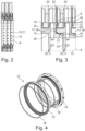
- Fig. 2 shows a section of the electrolysis stack 1 from Fig. 1 .
- One of the lines 9 can be seen.
- the representation of the Fig. 2 applies to both Fig. 1 marked lines 9.
- Openings can be seen distributed around the circumference of the line 9, which represent the anode-side connections 10 and the cathode-side connections 11, respectively. Three of the segments 12 are shown. These are shown in more detail in the following figures.
- Fig. 3 shows an excerpt from Fig. 2 .
- the segments 12 are each formed by a first part 14 and a second part 15 made of a polymer. Between the first part 14 and the second part 15, the diaphragm 8 of the electrolysis cell 2 assigned to the segment 12 and an elastic element 16 adjacent to the diaphragm 8 and formed to encircle the interior 13 of the line 9 are held. The diaphragms 8 are held merely in a force-fitting manner between the elastic element 16 and the second part 15 of the segment 12 assigned to the respective electrolysis cell 1.
- the segments 12 each have a section extending in the axial direction (in the example of the Fig. 3 to the left) and a receptacle 18.
- the projections 17 each engage, sealed by an O-ring 19, in the receptacle 18 of the segment 12 following in the axial direction.
- the receptacles 18 each have a recess 21 on a radially inner side 20 that extends around the interior 13 of the line 9.
- the O-rings 19 are each partially received in one of the recesses 21.
- the receptacles 18 and the projections 17 each have a thread 22.
- the projections 17 each engage, by means of the thread 22, into the receptacle 18 of the segment 12 following in the axial direction.
- the segments 12 are each spaced apart from the segment 12 following in the axial direction by a gap 23 formed outside the projection 17.
- Fig. 3 It can be seen that the bipolar plates 24 are held between the segments 12.
- the bipolar plates 24 are each held between the first part 14 of one of the segments 12 and the second part 15 of the segment 12 following in the axial direction.
- Fig. 4 shows a segment 12 for a line 9, as it is in the electrolysis stack 1 from the Fig. 1 to 3 can be used.
- the first part 14, the second part 15, the elastic element 16 and the O-ring 19 can be seen in particular.
Landscapes
- Chemical & Material Sciences (AREA)
- Engineering & Computer Science (AREA)
- Chemical Kinetics & Catalysis (AREA)
- Electrochemistry (AREA)
- Materials Engineering (AREA)
- Metallurgy (AREA)
- Organic Chemistry (AREA)
- Inorganic Chemistry (AREA)
- Electrolytic Production Of Non-Metals, Compounds, Apparatuses Therefor (AREA)
Priority Applications (2)
| Application Number | Priority Date | Filing Date | Title |
|---|---|---|---|
| EP23214837.9A EP4567155A1 (fr) | 2023-12-07 | 2023-12-07 | Étanchéité d'une pile d'électrolyse |
| PCT/EP2024/082969 WO2025119649A1 (fr) | 2023-12-07 | 2024-11-20 | Scellement d'un empilement d'électrolyse |
Applications Claiming Priority (1)
| Application Number | Priority Date | Filing Date | Title |
|---|---|---|---|
| EP23214837.9A EP4567155A1 (fr) | 2023-12-07 | 2023-12-07 | Étanchéité d'une pile d'électrolyse |
Publications (1)
| Publication Number | Publication Date |
|---|---|
| EP4567155A1 true EP4567155A1 (fr) | 2025-06-11 |
Family
ID=89121588
Family Applications (1)
| Application Number | Title | Priority Date | Filing Date |
|---|---|---|---|
| EP23214837.9A Pending EP4567155A1 (fr) | 2023-12-07 | 2023-12-07 | Étanchéité d'une pile d'électrolyse |
Country Status (2)
| Country | Link |
|---|---|
| EP (1) | EP4567155A1 (fr) |
| WO (1) | WO2025119649A1 (fr) |
Citations (2)
| Publication number | Priority date | Publication date | Assignee | Title |
|---|---|---|---|---|
| US4076609A (en) * | 1975-01-14 | 1978-02-28 | Societe De Recherches Techniques Et Industrielles | Electrolysis apparatus |
| WO2016034183A1 (fr) * | 2014-09-05 | 2016-03-10 | Greenhydrogen.Dk Aps | Pile d'électrolyse sous pression |
-
2023
- 2023-12-07 EP EP23214837.9A patent/EP4567155A1/fr active Pending
-
2024
- 2024-11-20 WO PCT/EP2024/082969 patent/WO2025119649A1/fr active Pending
Patent Citations (2)
| Publication number | Priority date | Publication date | Assignee | Title |
|---|---|---|---|---|
| US4076609A (en) * | 1975-01-14 | 1978-02-28 | Societe De Recherches Techniques Et Industrielles | Electrolysis apparatus |
| WO2016034183A1 (fr) * | 2014-09-05 | 2016-03-10 | Greenhydrogen.Dk Aps | Pile d'électrolyse sous pression |
Also Published As
| Publication number | Publication date |
|---|---|
| WO2025119649A1 (fr) | 2025-06-12 |
Similar Documents
| Publication | Publication Date | Title |
|---|---|---|
| EP0020887B1 (fr) | Appareil d'électrolyse pour la production de chlore à partir de solutions aqueuses d'halogénures de métaux alcalins | |
| DE2646463A1 (de) | Plattenelektrode fuer eine elektrolysezelle | |
| CH618471A5 (fr) | ||
| DE2809333C2 (de) | Monopolare Elektrolysezelle in Filterpressenbauweise | |
| DD209853A5 (de) | Elektrolysezelle und dichtung fuer eine elektrolysezelle | |
| DE19781442C1 (de) | Druckwassergekapselter Elektrolyseur | |
| EP3696298A1 (fr) | Bloc d'électrolyse et cadre pour cellule correspondant | |
| EP4399351A2 (fr) | Cadre pour cellules électrochimiques et dispositifs de type à empilement | |
| DE2328770A1 (de) | Dichtung zwischen bipolarer elektrode und trennplatte | |
| DE102022206852A1 (de) | Bipolarplatte für einen PEM-Elektrolyseur und PEM-Elektrolyseur | |
| EP4274919B1 (fr) | Dispositif d'électrolyse | |
| DE102012216920A1 (de) | Elektrolyseblock sowie Zellrahmen, Elektrodenbaugruppe und Bausatz hierfür | |
| DE102022202986A1 (de) | Elektrochemische Zelle für einen Hochdruckelektrolyseur | |
| EP1573089B1 (fr) | Electrolyseur sous pression et cadre de cellule destine a un tel electrolyseur | |
| EP4567155A1 (fr) | Étanchéité d'une pile d'électrolyse | |
| DD250138A5 (de) | Elektrolytische zelle | |
| DE102024114144A1 (de) | Separatorplatte und Zellrahmen für eine elektrochemische Vorrichtung | |
| DE102019218870A1 (de) | Brennstoffzelle, Brennstoffzellenstapel sowie Verfahren zum Betreiben eines Brennstoffzellenstapels | |
| EP4705542A1 (fr) | Empilement de cellules électrochimiques et procédé de fonctionnement d'un empilement de cellules électrochimiques | |
| DE2653536A1 (de) | Bipolare elektrolysiereinrichtung mit einer elektrolytausgleichseinrichtung | |
| DE4418999C2 (de) | Druckelektrolyseur mit einem gekapselten Zellenblock aus einzelnen Elektrolysezellen | |
| EP0776994B1 (fr) | Electrolyseur à électrolyte fluide | |
| AT525988A4 (de) | Anlage zur Reduktion von Kohlenstoffdioxid und Elektrolysezelle hierfür | |
| EP4278030B1 (fr) | Dispositif d'électrolyse | |
| AT526359B1 (de) | Dreikammerzelle |
Legal Events
| Date | Code | Title | Description |
|---|---|---|---|
| PUAI | Public reference made under article 153(3) epc to a published international application that has entered the european phase |
Free format text: ORIGINAL CODE: 0009012 |
|
| STAA | Information on the status of an ep patent application or granted ep patent |
Free format text: STATUS: THE APPLICATION HAS BEEN PUBLISHED |
|
| AK | Designated contracting states |
Kind code of ref document: A1 Designated state(s): AL AT BE BG CH CY CZ DE DK EE ES FI FR GB GR HR HU IE IS IT LI LT LU LV MC ME MK MT NL NO PL PT RO RS SE SI SK SM TR |
|
| STAA | Information on the status of an ep patent application or granted ep patent |
Free format text: STATUS: REQUEST FOR EXAMINATION WAS MADE |
|
| 17P | Request for examination filed |
Effective date: 20251211 |