EP4567213A1 - Lamellendach und terrassenüberdachung damit - Google Patents
Lamellendach und terrassenüberdachung damit Download PDFInfo
- Publication number
- EP4567213A1 EP4567213A1 EP24216920.9A EP24216920A EP4567213A1 EP 4567213 A1 EP4567213 A1 EP 4567213A1 EP 24216920 A EP24216920 A EP 24216920A EP 4567213 A1 EP4567213 A1 EP 4567213A1
- Authority
- EP
- European Patent Office
- Prior art keywords
- slats
- gutter
- drain profile
- profile
- indirect lighting
- Prior art date
- Legal status (The legal status is an assumption and is not a legal conclusion. Google has not performed a legal analysis and makes no representation as to the accuracy of the status listed.)
- Pending
Links
Images
Classifications
-
- E—FIXED CONSTRUCTIONS
- E04—BUILDING
- E04B—GENERAL BUILDING CONSTRUCTIONS; WALLS, e.g. PARTITIONS; ROOFS; FLOORS; CEILINGS; INSULATION OR OTHER PROTECTION OF BUILDINGS
- E04B7/00—Roofs; Roof construction with regard to insulation
- E04B7/16—Roof structures with movable roof parts
- E04B7/163—Roof structures with movable roof parts characterised by a pivoting movement of the movable roof parts
-
- E—FIXED CONSTRUCTIONS
- E04—BUILDING
- E04F—FINISHING WORK ON BUILDINGS, e.g. STAIRS, FLOORS
- E04F10/00—Sunshades, e.g. Florentine blinds or jalousies; Outside screens; Awnings or baldachins
- E04F10/08—Sunshades, e.g. Florentine blinds or jalousies; Outside screens; Awnings or baldachins of a plurality of similar rigid parts, e.g. slabs, lamellae
- E04F10/10—Sunshades, e.g. Florentine blinds or jalousies; Outside screens; Awnings or baldachins of a plurality of similar rigid parts, e.g. slabs, lamellae collapsible or extensible; metallic Florentine blinds; awnings with movable parts such as louvres
Definitions
- the present invention relates to a slatted roof.
- the present invention further relates to a terrace canopy comprising such a slatted roof.
- Slatted roofs are usually installed to screen or rather free up an outdoor area.
- covers are often installed at homes, restaurants, shops, etc. to screen off an outdoor patio or the like from solar radiation, precipitation and/or wind, or rather to temporarily let solar radiation in.
- These covers can, for example, be in the form of an awning, pergola, veranda, carport, pavilion, etc.
- 'top' refers to the portion of the slatted roof that is or will be oriented towards the top surface (i.e. the sky, e.g. the open air)
- 'bottom' refers to the portion of the slatted roof that is or will be oriented towards the ground surface (i.e. the earth, e.g. the patio floor)
- 'outside' to the portion of the slatted roof that is or will be oriented away from the roof (i.e. away from the slats) and 'inside' to the portion of the slatted roof that is or will be oriented towards the inside of the slatted roof (i.e. facing the slats).
- a slatted roof typically comprises a frame comprising at least two beams which extend parallel to each other and to which multiple slats are connected so as to be rotatable between an open position and a closed position. In the open position, there is a gap between the slats and in the closed position, the slats together form a continuous cover. By rotating the slats between these positions, light incidence, radiant heat and ventilation to the space below the slats can be controlled. For example, by aligning the slats, sun and/or wind can be shielded or let through. In other words, the slatted roof acts as protection from the sun, precipitation, wind, etc. for a space located below it.
- the slats in their open position, can optionally be provided sliding in the slatted roof; in this case, they are typically movable between a position in which they are spread across the slatted roof and a position in which they are mainly installed on one side of the slatted roof.
- rotatable slats it is also possible to include one or multiple fixed slats in the slatted roof.
- a fixed slat is understood to mean a slat that is firmly connected to the beams and therefore neither rotatable nor movable.
- the beams to which the slats are connected are also referred to as ⁇ pivot beams'.
- the pivot beams are normally provided with a gutter for collecting and draining precipitation falling on the slats. This can be a separate gutter fastened to the pivot beam, as well as a profile that is an integral part of the pivot beam.
- Different embodiments of pivot beams are disclosed in WO 2021/214677 A1 , in particular in figures 3A to 3K thereof.
- a known problem in slatted roofs is splashing water when draining from the slats to the gutter/gutters in the pivot beam(s). This problem is described in BE 1027244 A1 .
- the problem originates in the limited height of the gutter, making the slats rotatable in such a way that, for example in strong wind, heavy rain, etc., water flowing off the slats does not end up in the gutter or falls into the gutter and splashes over the edge of the gutter.
- the lack of watertightness in the drainage area is of course undesirable.
- BE 1027244 A1 discloses ten different embodiments of the drain profile and eight different embodiments of the transfer means and various combinations thereof.
- slatted roofs Another known problem with slatted roofs is the lack of lighting on the bottom side of the slatted roof. This can be obtained, on the one hand, by providing a fixed (i.e. not rotatable) slat to which or in which lighting can be mounted. Such a concept is disclosed in WO 2023/031757 A1 and WO 2023/031758 A1 . Rotatable slats in which LED lighting or spotlights are integrated are also known. Another way to obtain lighting on the bottom side of the slatted roof is to use LED strips fastened to the frame as disclosed in DE 10 2016 117 774 A1 . These LED strips are directly visible by a person under the slatted roof and can be perceived as disturbing, e.g. due to excessive light intensity. The use of directly visible lighting embedded in the pivot beam is also disclosed in WO 2021/214677 A1 , i.e. in Figure 3K, where lighting can be mounted on the bottom side of the gutter.
- a slatted roof according to the preamble of claim 1 is disclosed in EP 4148202 A1 .
- a movable splash wall is arranged above the gutter, as well as indirect lighting on a free top edge of the gutter.
- the side of the splash wall facing the indirect lighting is mainly flat.
- the drain profile in its closed position, has a side facing the indirect lighting, which side is smooth and concave.
- indirect lighting creates an additional way to provide lighting on the bottom side of the slats without having to use a fixed slat.
- the indirect lighting also avoids the disadvantages associated with current LED strips that are directly visible to a person under the slatted roof.
- the movable drain profile is a known solution for improving watertightness in the drainage area. This solution is disclosed in BE 1027244 A1 and is based on providing a separate drain profile that can be moved together with the slats. As described in more detail below, the drain profile is ideally suited for use together with the indirect lighting because it allows certain parts of the gutter to be (substantially) free of precipitation. These parts of the gutter are therefore ideally suited for mounting the light.
- the side of the drain profile facing the indirect lighting generally serves as a reflector for redirecting the light emitted by the indirect lighting.
- the use of a smooth concave reflector facing the light ensures improved diffusion and reorientation of the light emitted by the lighting. In addition, this prevents shadow lines that typically occur when using angled reflectors.
- One embodiment of the present invention is characterised in that the gutter is bounded by a raised wall, wherein the indirect lighting is arranged near a free top edge of the raised wall.
- the raised wall on the side facing the pivot beam has an (LED strip) holder in which the indirect lighting is arranged.
- Arranging the lighting on the top side of the gutter lowers the risk of water problems compared to other locations for arranging lighting in the gutter (such as the bottom). This is because the top side of the gutter is typically mostly free of moisture.
- Providing a (LED strip) holder further allows the indirect lighting, e.g. in the form of an LED strip, to be mounted quickly and easily. There is therefore also no need to use additional fastening means, thereby avoiding additional components and reducing installation time.
- This (LED strip) holder also further reduces the distance between the raised gutter wall and the drain profile, such that there is even less space for splashing moisture.
- One embodiment of the present invention is characterised in that the drain profile has a free bottom edge which, in the closed position of the drain profile, extends into the gutter to near or beyond the indirect lighting.
- drain profile also shields the indirect lighting from the drained precipitation. This may possibly be achieved in combination with the (LED strip) holder that shields the bottom side of the lighting from splashing precipitation.
- One embodiment of the present invention is characterised in that the indirect lighting is configured to emit light mainly upwards.
- the indirect lighting and the gutter of the pivot beam can be generally designed to direct light in any direction
- the simplest design is suitable for directing light upwards (i.e. straight to the bottom side of the slats).
- This allows, for example, a U-shaped light holder to be provided with the open side at the top side of the gutter parallel to the bottom side of the slats. In this manner, the side facing the gutter and the bottom side of the lighting is already protected from splashing moisture. Furthermore, this minimises the space taken up by the lighting compared to an inclined U-shaped light holder that could be used to emit light to the pivot beam.
- the use of upwardly directed light also allows the design of the bottom side of the drain profile to be chosen without having to consider the effects on the lighting.
- the bottom side of the drain profile can be designed with complete focus on avoiding splashing moisture.
- One embodiment of the present invention is characterised in that the side facing the indirect lighting is shaped so that, in the closed position of the drain profile, light incident on the drain profile from the indirect lighting is deflected to illuminate at least 25%, in particular at least 30%, of the bottom side of the slats.
- a person skilled in the art is generally familiar with reflectors and their operation and is therefore able, given the light source, to shape the surface of the reflector to redirect the light to illuminate at least 25% of the bottom side of the slats.
- at least 25% of the bottom side of the slats means that each slat is illuminated by the indirect lighting from its end at the gutter over a distance of 25% of the total length of the slat (measured in the longitudinal direction of the slat).
- the drain profile comprises a mainly flat part which, in the closed position of the drain profile, has an angle of inclination relative to the slats such that incident light is directed substantially parallel to the slats.
- Such a mainly flat ensures almost uniform bending of the light such that the light intensity remains uniform (or at least it remains as emitted by the indirect lighting).
- the light distribution is typically uniform as viewed in the depth direction of the LED strip. Directing the light substantially parallel to the slats maximises the surface area of the slats that is illuminated. In case the light emitted by the indirect lighting is mainly upward, this angle of inclination is typically about 45°.
- One embodiment of the present invention is characterised in that the drain profile has a side which faces the slats and through which said precipitation falling on the slats is drained to the gutter, wherein the side facing the indirect lighting and the side facing the slats are opposite sides of the same profile and preferably the same wall.
- the same profile therefore has a dual function, namely to divert water from the slats to the gutter including avoiding splashing thereof as well as to redirect the indirect lighting to illuminate the bottom side of the slats.
- the use of a single-walled profile limits the amount of material required to manufacture the profile. This also limits the weight of the profile, such that other components of the slatted roof (e.g. the fastening of the drain profile to the pivot beam) do not have to be as robust and sturdy.
- the drain profile has a side which faces the slats and is configured for draining precipitation falling onto the slats into the gutter, which side is smooth and convex.
- a top of this convex side is located, in the open position of the drain profile, below the slats.
- the smooth and convex shape is advantageous for drainage. Moreover, even in the open position of the slats, it is possible for precipitation to still flow from the slats into the gutter (e.g. residual precipitation on the slats). By providing the top of the convex side below the slat and thus away from the end of the slat, such precipitation falls on an inclined wall that slopes down to the gutter. This further reduces the risk of splashing moisture.
- One embodiment of the present invention is characterised in that the drain profile has a side which faces the slats, wherein a stop is arranged on said side facing the slats, which stop strikes against the slats whatever the position of the slats.
- the stop is part of a specific way in which the drain profile is moved between its open position and its closed position.
- This specific way is namely through ensuring that the drain profile makes contact with the slats such that a rotation of the slats directly results in a movement of the drain profile.
- a stop such as an impact pad or the like, is advantageous.
- this prevents damage to the slats and/or the drain profile.
- the stop can also serve to absorb small differences between the placement of different slats and/or tolerances on the drain profile that could be detrimental to its operation. Furthermore, this can contribute to a proper seal between the drain profile and the bottom side of the slats for the avoidance of draughts, insects, dirt, etc.
- One embodiment of the present invention is characterised in that the drain profile has a bottom edge located within the gutter for each position of the drain profile.
- One embodiment of the present invention is characterised in that the drain profile is hingedly fastened to the pivot beam.
- One embodiment of the present invention is characterised in that a spring means is provided for moving (e.g. pushing) the drain profile to the open position, which spring means is in particular provided between the pivot beam and the drain profile, and wherein the drain profile is configured to be pushed against the spring means to its open position by a rotation of the slats to their open position.
- the frame comprises a further pivot beam mainly parallel to the pivot beam, wherein the slats are rotatably fastened at their ends to the pivot beams, for example by means of slat axles, wherein a further gutter is fastened to the further pivot beam and extends to below an end of the slats, wherein further indirect lighting is arranged within the further gutter for illuminating a bottom side of the slats and wherein a further drain profile is fastened to the further pivot beam, which further drain profile is movable between a closed position for draining precipitation falling onto the slats into the further gutter and an open position allowing rotation of the slats to their open position.
- One embodiment of the present invention is characterised in that the drain profile and the further drain profile are identical and are each fastened to a respective pivot beam at a different height relative to a respective gutter.
- the slats are typically installed at an inclination (e.g. at an angle of 2°) to one end to avoid standing water.
- an inclination e.g. at an angle of 2°
- the term 'substantially' or 'mainly' comprises variations of +/- 10% or less, preferably +/-5% or less, more preferably +/-1 % or less, and more preferably +/-0.1% or less, of the specified condition, in so far as the variations are applicable for operation in the present invention. It should be understood that the term 'substantially A' or 'mainly A' is intended to comprise 'A' as well.
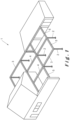
- Figure 1 illustrates a (terrace) canopy 1 for a ground surface, for example a patio or garden.
- the canopy comprises a plurality of columns 2 supporting various beams 3, 4, 5. Together, the columns and beams form frames to which wall infills 6 and/or roof coverings 7 can be fastened as described below.
- the canopy 1 generally comprises three types of beams 3, 4, 5, namely: a beam 3 that serves as an external pivot beam 3 on the outside of the canopy 1; a beam 4 that serves as a central pivot beam 4 at the centre of the canopy 1; and a beam 5 that serves as a tension beam 5.
- the beams 3, 4, 5 can be fastened to other structures, for example a wall or façade, instead of solely supporting columns 2 as shown in Figure 1 . In such a manner, the canopy 1 can be generally used to screen an outdoor space, as well as an indoor space.
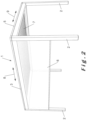
- the (terrace) canopy 1 shown in Figure 2 comprises four support columns 2 supporting a frame, also called a roof frame.
- the frame is formed of two external pivot beams 3 and two tension beams 5 between which a roof covering 7 is provided.
- a wall infill 6 can optionally be provided between two support columns 2 and a pivot beam 3 or tension beam 5.
- Wall infills 6 are typically intended to cover openings under the canopy 1 between the columns 2.
- the wall infills 6 can be permanently installed or movable.
- Movable sidewalls comprise, for example, roll-up and roll-down screens and/or wall elements that are installed so as to be movable relative to each other, etc. Fixedly installed side walls can be made of various materials, such as plastic, glass, metal, textile, wood, etc. Combinations of different wall infills 6 are also possible.
- Figure 2 illustrates a wall infill in the form of a roll-up and roll-down screen 6.
- the screen 6 extends between two adjacent columns 2 and is unrollable from the external pivot beam 3.
- the screen 6 primarily serves as a windscreen and/or sunshade.
- the roof covering 7 is formed by slats rotatably (also referred to as pivotably) fastened at their end ends to pivot beams 3.
- the slats are rotatable between an open position and a closed position. In the open position, there is a space between the slats through which, for example, air can enter or leave the underlying space.
- the slats In the closed position, the slats form a closed canopy that can protect the underlying space from, for example, wind and/or precipitation such as rain, hail or snow. As precipitation drains away, the slats are typically installed at an angle towards one of the two pivot beams 3.
- Figure 2 illustrates the closed position wherein the slats 7 together form a substantially continuous covering. In the open position (not shown), a gap is present between the slats 7.
- ⁇ lengthwise direction or longitudinal direction of the slatted roof' means the direction along which the pivot beams 3 extend as indicated by arrow 8 in Figure 2 .
- the term 'transverse direction of the slatted roof' means the direction along which the slats 7 extend as indicated by arrow 9 in Figure 2 .
- the lengthwise direction and transverse direction of the slatted roof are substantially perpendicular to each other.
- ⁇ lengthwise direction or longitudinal direction of a slat' means the direction along which the slats 7 extend as indicated by arrow 36 in Figure 3A.
- the directions 9 and 36 typically coincide.
- the term 'transverse direction of a slat' means the direction that is substantially perpendicular to the lengthwise direction of a slat as indicated by arrow 37 in Figure 3A.
- the directions 8 and 37 typically coincide.
- the slats are typically made of a rigid material. This can be aluminium, for example. Aluminium has many advantages as a material, as it is simultaneously robust and light, resistant to adverse weather conditions and requires little maintenance. However, other materials are also suitable and their advantages or disadvantages are assumed to be known by a person skilled in the art.
- a slat can be produced using different techniques depending on the material, including extrusion, milling, setting, casting, welding and so on. The appropriate production technique is assumed to be known by a person skilled in the art. Preferably, the slats are manufactured by an extrusion process.
- filler elements made of, for example, polycarbonate, glass, wood, etc., can be used to at least partially fill the hollow slats, for example to obtain a different appearance of the slat, in particular if the slat is manufactured from a transparent material, such as glass.
- the slats 7 By rotating the slats 7 between the open position and the closed position, light incidence, radiant heat and ventilation to the space below the slats can be controlled.
- the open position there is a space between the slats 7 through which, for example, air can enter or leave the underlying space.
- the closed position the slats 7 form a closed canopy that can protect the underlying space from, for example, wind and/or precipitation such as rain, hail or snow.
- the fastening typically uses a shaft that passes through the slat 7 and connects to an end piece provided with a slat axle 10 that engages with an opening in the pivot beams 3, which opening is typically provided with a bearing. It should be clear that other connections, for example without an end piece, wherein the lamella shaft is in that case present directly on the slat, are also possible.
- each slat 7 is arranged in the roof frame according to the principle of double bearing. In other words, each slat 7 is connected at both its ends to the roof frame. This can be a fixed or movable, in particular rotatable, fastening.
- the length L of a slat 7 is defined as the distance between its ends as viewed in the longitudinal direction 36 of the slat 7.
- a slat 7 can typically have a length of 2 to more than 5 m.
- any reference to an orientation of the pivot beams shall be interpreted with reference to the position when mounted in the terrace canopy.
- 'top' refers to the portion of the beam that is or will be oriented towards the top surface (the sky, e.g. the open air)
- 'bottom' refers to the portion of the beam that is or will be oriented towards the ground surface (the earth, e.g. the patio floor)
- 'outside' to the portion of the beam that is or will be oriented away from the roof, i.e. away from the slatted roof and 'inside' to the portion of the beam that is or will be oriented towards the inside of the roof, i.e. facing the slatted roof.
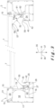
- Figure 3 shows a front view of a slat 7 fastened to two pivot beams 3 in the closed position of the slat 7.
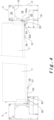
- Figure 4 shows the same view as Figure 3 with the slat 7 in its open position.
- the pivot beams are each formed by assembling multiple profiles.
- the base profile 15 and the gutter profile 16 typically encloses an internal cavity 18 into which a screen roll with a screen rolled thereon can be inserted to serve as a wall infill 6.
- the base profile 15 has a on the inside a raised wall 19 to which the slats 7 are fastened.
- a cover profile 21 is provided which, together with the base profile 15, encloses an internal space 20 in which electrical and/or electronic components for driving the slats can be provided.
- the gutter profile 16 is first provided with an external gutter 24 bounded by a bottom 26 and a raised inner wall 25.
- the external gutter 24 extends to below the end of the slats 7, such that precipitation falling on the slats is collected in the external gutter 24.
- the gutter profile 16 also has an internal gutter 22 separated from the external gutter 24 by a raised wall 27. This wall 27 is provided with openings or perforations so that precipitation collected in the external gutter 24 can flow to the internal gutter 22.
- the internal gutter 22 then connects to a drain provided for this purpose inside the column 2. It should be clear that the use of an internal gutter 22 is optional.
- Various slatted roofs are known in which the external gutter 24 near a corner point of the slatted roof is directly connected to a drain provided in or on the column.
- pivot beam In the figures shown, only one embodiment of pivot beam is shown. However, various embodiments are possible as disclosed in WO 2021 /214677 A1 and can also be used in the frame of the present invention.
- a pin connection typically an elastic element (not shown) is present in a female element, for example a slot element, into which a male element, for example a pin, engages.
- a pin connection generally comprises an elastic interlocking male and female element; for this purpose, an additional elastic element can be provided, but this is not necessarily the case.
- the elasticity can also result from the shape of the male and female elements.
- a hook connection typically involves two elements with a shape such that they hook into each other. In this case, there is no elastic element and the connection is broken apart by moving the elements in the correct direction relative to each other.
- the profiles 15, 16, 17, 21 are typically made of a rigid material.
- This can be aluminium, for example. Aluminium has many advantages as a material, as it is simultaneously robust and light, resistant to adverse weather conditions and requires little maintenance. However, other materials are also suitable and their advantages or disadvantages are assumed to be known by a person skilled in the art.
- a profile can be produced using different techniques depending on the material, including extrusion, milling, setting, casting, welding and so on, although extrusion is preferred. The appropriate production technique is assumed to be known by a person skilled in the art.
- the pivot beams 3 and/or several of the profiles can be manufactured integrally as a single beam and/or a single profile.
- the disadvantage of this is that, given its considerable height, such a profile is not easy to manufacture by an extrusion process.
- the present invention generally comprises a drain profile 50 fastened to the pivot beam 3 and movable between a closed position (shown in Figure 3 ) for draining precipitation falling onto the slats 7 into the gutter 24 and an open position (shown in Figure 4 ) allowing rotation of the slats 7 to their open position.
- This drain profile 50 is based on the concept disclosed in BE 1027244 A1 but, in the embodiment shown, is optimised to cooperate with indirect lighting 40 to illuminate the bottom side of the slats 7 as described in further detail below.
- the drain profile 50 is rotatably fastened to the pivot beam 3.
- a holder 60 is fastened, e.g. by fastening means 61 such as a bolt, to the raised wall 19 of the pivot beam 3.
- fastening means 61 such as a bolt
- the holder 60 is fastened at different heights along the raised wall 19 in front of the opposite pivot beams 3.
- the drain profile 50 is fastened to the holder 60 by means of various torsion springs 62. More specifically, one free end 62a of a torsion spring 62 is fixed in the holder 60 and the other free end 62b is fixed in a groove 64 provided for that purpose on the drain profile 50.
- Such torsion springs 62 are arranged at various places along the drain profile 50. These torsion springs 62 push the drain profile 50 into its closed position. Other means can also be used to move the drain profile 50.
- the drain profile 50 shown is mainly designed as a single wall that has a side 54 facing the slats and an opposite side 52 that, as described in further detail below, faces the indirect lighting 40 and serves as a reflector for the indirect lighting 40.
- the side 54 facing the slats serves to drain precipitation from the slats 7 to the external gutter 24.
- the drain profile can be composed of multiple separate profiles or of one profile with multiple walls.
- the drain profile 50 extends between a top free edge 57 and a bottom free edge 59.
- the bottom free edge 59 is always in the external gutter 24 regardless of the position of the drain profile 50. This prevents the drained precipitation from still passing through the external gutter 24.
- the placement of the bottom free edge 59 in relation to the external gutter 24 is especially crucial in the closed position of the slats 7 (shown in Figure 3 ) as there is only precipitation drainage in this position.
- a holder 56 is provided into which a stop 58 is inserted.
- This stop 58 is typically an impact pad, e.g. an elastic element. This prevents damage to the slats 7 and/or the drain profile 50.
- This stop 58 is, in the embodiment shown, always in direct contact with the slats 7. When the slats 7 are being opened (i.e. when they are being turned), a downward force is exerted on this stop 58 causing the drain profile 50 to be moved against the torsion springs 62 to its open position shown in Figure 4 .
- the drain profile 50 is typically made of a rigid material.
- This can be aluminium, for example. Aluminium has many advantages as a material, as it is simultaneously robust and light, resistant to adverse weather conditions and requires little maintenance. However, other materials are also suitable and their advantages or disadvantages are assumed to be known by a person skilled in the art.
- a profile can be produced using different techniques depending on the material, including extrusion, milling, setting, casting, welding and so on, although extrusion is preferred. The appropriate production technique is assumed to be known by a person skilled in the art.
- the present invention generally comprises indirect lighting 40 for illuminating the bottom side of the slats 7.
- This lighting 40 is arranged inside the external gutter 24 and is therefore not directly visible to a person under the slatted roof.
- the lighting 40 is in the form of an LED strip arranged in a holder 42 provided for that purpose.
- the holder 42 is generally U-shaped and is located at the top free edge of the raised wall 25 forming the external gutter 24.
- a U-shaped holder 42 is advantageous as the lighting 40 is in this case immediately protected on three sides against precipitation and/or splashing moisture.
- the indirect lighting 40 is intended to emit light mainly upwards (i.e. following direction 35, which is both perpendicular to the longitudinal direction 9/36 of the slats 7 and perpendicular to the longitudinal direction 8/37 of the pivot beam 3) towards the slats 7.
- the indirect lighting 40 can be placed so as to direct light in any direction, but this often has disadvantages. If, for example, it were decided to emit light at an angle of 45° (with respect to the upward direction 35) away from the pivot beam 3, the top free edge of the gutter wall 25 on the visible side would block part of the emitted light. If, for example, it were decided to direct light at an angle of 45° (with respect to the upward direction 35) to from the pivot beam 3, the holder 42 would take up more space inside the external gutter 24 and the design of the drain profile 50 would have to be changed.
- the use of upwardly directed light also allows the design of the bottom side of the drain profile 50 to be chosen without having to consider the effects on the lighting.
- the bottom side of the drain profile 50 can be designed with complete focus on avoiding splashing moisture. In the embodiment shown, this is also done by arranging a curvature in the bottom side of the drain profile 50 so that the free bottom end is closer to the raised edge 25 than in an embodiment in which the bottom side extends straight down from the coupling with the torsion springs 62 (as shown, for example, in Figure 3 of BE 1027244 A1 ).
- the bottom edge 59 of the drain profile 50 is located in the external gutter 24. Preferably this is near the holder 42 for the indirect lighting 40 or, even better, beyond this holder 42 as is the case in the left pivot beam 3 in Figure 3 . This minimises the risk that water falling into the gutter 24 may splash and thus reach the lighting 40.
- the main difference between the drain profile 50 shown and the one disclosed in BE 1027244 A1 is the design of the side 52 (i.e. the reflector) facing the indirect lighting.
- This reflector is in fact smooth and concave along its entire length.
- the term 'smooth' here refers to the mathematical meaning in the sense that a function describing the design of the indirect lighting-facing side 52 of the drain profile 50 can be derived at least once. Such a smooth surface ensures optimal diffusion and reorientation of the indirect lighting and avoids the formation of shadow lines that would be present in the case of an angled drain profile 50 (as shown, for example, in Figure 3 of BE 1027244 A1 ).
- the top side of the drain profile 50 on its side facing the indirect lighting 52 is substantially flat with an angle of inclination of about 45° with respect to the upward direction 35. This ensures that the emitted light is substantially parallel to the bottom side of the slats 7. In this manner, the slats are illuminated over as large a part as possible (e.g. over at least 25% of their length from the pivot beam 3). The emitted light will also gradually decrease towards the centre of the slats 7 due to natural scattering of light.
- a flexible safety net for catching leaves and the like can additionally be arranged between the drain profile 50 and the pivot beam 3.
- This safety net prevents leaves and/or other large debris from entering the gutter 24, which could lead to blockages.
- This safety net can be fastened, for example, on one side to the raised wall 19, e.g. to the holder 60 and on the other side to the free bottom edge 59 of the drain profile 50 or to the 54 facing the slats by providing a suitable holder there.
Landscapes
- Engineering & Computer Science (AREA)
- Architecture (AREA)
- Civil Engineering (AREA)
- Structural Engineering (AREA)
- Physics & Mathematics (AREA)
- Electromagnetism (AREA)
- Specific Sealing Or Ventilating Devices For Doors And Windows (AREA)
- Roof Covering Using Slabs Or Stiff Sheets (AREA)
Applications Claiming Priority (1)
| Application Number | Priority Date | Filing Date | Title |
|---|---|---|---|
| BE20235984A BE1032199B1 (nl) | 2023-12-04 | 2023-12-04 | Lamellendak en terrasoverkapping omvattende hetzelfde |
Publications (1)
| Publication Number | Publication Date |
|---|---|
| EP4567213A1 true EP4567213A1 (de) | 2025-06-11 |
Family
ID=89158501
Family Applications (1)
| Application Number | Title | Priority Date | Filing Date |
|---|---|---|---|
| EP24216920.9A Pending EP4567213A1 (de) | 2023-12-04 | 2024-12-02 | Lamellendach und terrassenüberdachung damit |
Country Status (2)
| Country | Link |
|---|---|
| EP (1) | EP4567213A1 (de) |
| BE (1) | BE1032199B1 (de) |
Citations (8)
| Publication number | Priority date | Publication date | Assignee | Title |
|---|---|---|---|---|
| CH662146A5 (en) * | 1983-11-24 | 1987-09-15 | Alu System Ag | Lamellar roofing means |
| DE102016117774A1 (de) | 2016-09-21 | 2018-03-22 | Jürgen Grimmeisen | Lamellendesign |
| BE1027244A1 (nl) | 2019-04-30 | 2020-11-25 | Renson Sunprotection Screens Nv | Lamellendak |
| WO2021214677A1 (en) | 2020-04-21 | 2021-10-28 | Renson Sunprotection-Screens | Terrace canopy |
| WO2022084871A1 (en) | 2020-10-22 | 2022-04-28 | Renson Sunprotection-Screens | Slat roof for a canopy, kit of parts for assembling the slat roof, canopy comprising the slat roof |
| WO2023031757A1 (en) | 2021-08-30 | 2023-03-09 | Renson Sunprotection-Screens | Slatted roof, terrace canopy comprising the same, and a kit of parts and a method for assembling the same |
| WO2023031758A1 (en) | 2021-08-30 | 2023-03-09 | Renson Sunprotection-Screens | Slat roof, terrace canopy comprising the same, and a kit of parts for assembling the same |
| EP4148202A1 (de) | 2021-09-08 | 2023-03-15 | Peuchot, Alainfr | Pergola mit verbessertem schutz gegen das eindringen von wasser und/oder wind, die geeignet ist, um licht in den von der pergola geschützten raum zu lenken |
-
2023
- 2023-12-04 BE BE20235984A patent/BE1032199B1/nl active IP Right Grant
-
2024
- 2024-12-02 EP EP24216920.9A patent/EP4567213A1/de active Pending
Patent Citations (8)
| Publication number | Priority date | Publication date | Assignee | Title |
|---|---|---|---|---|
| CH662146A5 (en) * | 1983-11-24 | 1987-09-15 | Alu System Ag | Lamellar roofing means |
| DE102016117774A1 (de) | 2016-09-21 | 2018-03-22 | Jürgen Grimmeisen | Lamellendesign |
| BE1027244A1 (nl) | 2019-04-30 | 2020-11-25 | Renson Sunprotection Screens Nv | Lamellendak |
| WO2021214677A1 (en) | 2020-04-21 | 2021-10-28 | Renson Sunprotection-Screens | Terrace canopy |
| WO2022084871A1 (en) | 2020-10-22 | 2022-04-28 | Renson Sunprotection-Screens | Slat roof for a canopy, kit of parts for assembling the slat roof, canopy comprising the slat roof |
| WO2023031757A1 (en) | 2021-08-30 | 2023-03-09 | Renson Sunprotection-Screens | Slatted roof, terrace canopy comprising the same, and a kit of parts and a method for assembling the same |
| WO2023031758A1 (en) | 2021-08-30 | 2023-03-09 | Renson Sunprotection-Screens | Slat roof, terrace canopy comprising the same, and a kit of parts for assembling the same |
| EP4148202A1 (de) | 2021-09-08 | 2023-03-15 | Peuchot, Alainfr | Pergola mit verbessertem schutz gegen das eindringen von wasser und/oder wind, die geeignet ist, um licht in den von der pergola geschützten raum zu lenken |
Also Published As
| Publication number | Publication date |
|---|---|
| BE1032199B1 (nl) | 2025-06-30 |
| BE1032199A1 (nl) | 2025-06-27 |
Similar Documents
| Publication | Publication Date | Title |
|---|---|---|
| EP3234273B1 (de) | Pergolaabdeckung | |
| BE1028223B1 (nl) | Een ligger voor een overkapping | |
| KR101904280B1 (ko) | 파고라 차양구조체 | |
| EP4396421B1 (de) | Lamellendach, terrassenüberdachung damit und teilesatz und verfahren zur montage davon | |
| US20240141650A1 (en) | Roof arrangement for a terrace canopy, kit of parts for building the roof arrangement, and terrace canopy comprising the roof arrangement | |
| EP4567213A1 (de) | Lamellendach und terrassenüberdachung damit | |
| EP4396422B1 (de) | Lamellendach, terrassenüberdachung damit und teilesatz zur montage davon | |
| BE1027851B1 (nl) | Dakinrichting voor een overkapping | |
| EP4414519A1 (de) | Dacheindeckung mit beweglichen lamellen | |
| BE1028221B1 (nl) | Een set profielen voor het opbouwen van een overkapping | |
| JP2006274666A (ja) | 屋根 | |
| KR20220124874A (ko) | 통기구를 갖춘 차양막 | |
| BE1032850B1 (nl) | Lamellendak, terrasoverkapping omvattende hetzelfde, en een set onderdelen voor het opbouwen daarvan | |
| JP2006274665A (ja) | 屋根 | |
| JP2006274664A (ja) | 屋根 | |
| JP4850348B2 (ja) | ルーフ装置 |
Legal Events
| Date | Code | Title | Description |
|---|---|---|---|
| PUAI | Public reference made under article 153(3) epc to a published international application that has entered the european phase |
Free format text: ORIGINAL CODE: 0009012 |
|
| STAA | Information on the status of an ep patent application or granted ep patent |
Free format text: STATUS: THE APPLICATION HAS BEEN PUBLISHED |
|
| AK | Designated contracting states |
Kind code of ref document: A1 Designated state(s): AL AT BE BG CH CY CZ DE DK EE ES FI FR GB GR HR HU IE IS IT LI LT LU LV MC ME MK MT NL NO PL PT RO RS SE SI SK SM TR |
|
| STAA | Information on the status of an ep patent application or granted ep patent |
Free format text: STATUS: REQUEST FOR EXAMINATION WAS MADE |
|
| 17P | Request for examination filed |
Effective date: 20251204 |
|
| GRAP | Despatch of communication of intention to grant a patent |
Free format text: ORIGINAL CODE: EPIDOSNIGR1 |
|
| STAA | Information on the status of an ep patent application or granted ep patent |
Free format text: STATUS: GRANT OF PATENT IS INTENDED |
|
| INTG | Intention to grant announced |
Effective date: 20260114 |
|
| GRAS | Grant fee paid |
Free format text: ORIGINAL CODE: EPIDOSNIGR3 |