EP4567227A1 - Serrure à combinaison avec clé de surpassement - Google Patents
Serrure à combinaison avec clé de surpassement Download PDFInfo
- Publication number
- EP4567227A1 EP4567227A1 EP24217829.1A EP24217829A EP4567227A1 EP 4567227 A1 EP4567227 A1 EP 4567227A1 EP 24217829 A EP24217829 A EP 24217829A EP 4567227 A1 EP4567227 A1 EP 4567227A1
- Authority
- EP
- European Patent Office
- Prior art keywords
- lock
- assembly
- plate
- knob
- knob assembly
- Prior art date
- Legal status (The legal status is an assumption and is not a legal conclusion. Google has not performed a legal analysis and makes no representation as to the accuracy of the status listed.)
- Pending
Links
Images













Classifications
-
- E—FIXED CONSTRUCTIONS
- E05—LOCKS; KEYS; WINDOW OR DOOR FITTINGS; SAFES
- E05B—LOCKS; ACCESSORIES THEREFOR; HANDCUFFS
- E05B37/00—Permutation or combination locks; Puzzle locks
- E05B37/0031—Locks with both permutation and key actuation
- E05B37/0034—Locks with both permutation and key actuation actuated by either
-
- E—FIXED CONSTRUCTIONS
- E05—LOCKS; KEYS; WINDOW OR DOOR FITTINGS; SAFES
- E05B—LOCKS; ACCESSORIES THEREFOR; HANDCUFFS
- E05B13/00—Devices preventing the key or the handle or both from being used
- E05B13/10—Devices preventing the key or the handle or both from being used formed by a lock arranged in the handle
- E05B13/103—Combination lock
-
- E—FIXED CONSTRUCTIONS
- E05—LOCKS; KEYS; WINDOW OR DOOR FITTINGS; SAFES
- E05B—LOCKS; ACCESSORIES THEREFOR; HANDCUFFS
- E05B37/00—Permutation or combination locks; Puzzle locks
- E05B37/0031—Locks with both permutation and key actuation
- E05B37/0041—Key actuation allowing recovery of a lost/forgotten combination
-
- E—FIXED CONSTRUCTIONS
- E05—LOCKS; KEYS; WINDOW OR DOOR FITTINGS; SAFES
- E05B—LOCKS; ACCESSORIES THEREFOR; HANDCUFFS
- E05B37/00—Permutation or combination locks; Puzzle locks
- E05B37/0048—Permutation or combination locks; Puzzle locks with changeable combination
- E05B37/0058—Permutation or combination locks; Puzzle locks with changeable combination by axial disengagement between hub and rim of tumbler discs or rings
-
- E—FIXED CONSTRUCTIONS
- E05—LOCKS; KEYS; WINDOW OR DOOR FITTINGS; SAFES
- E05B—LOCKS; ACCESSORIES THEREFOR; HANDCUFFS
- E05B37/00—Permutation or combination locks; Puzzle locks
- E05B37/0075—Automatic scrambling
- E05B37/0079—Automatic scrambling when unlocking
-
- E—FIXED CONSTRUCTIONS
- E05—LOCKS; KEYS; WINDOW OR DOOR FITTINGS; SAFES
- E05B—LOCKS; ACCESSORIES THEREFOR; HANDCUFFS
- E05B37/00—Permutation or combination locks; Puzzle locks
- E05B37/12—Permutation or combination locks; Puzzle locks with tumbler discs on several axes
-
- E—FIXED CONSTRUCTIONS
- E05—LOCKS; KEYS; WINDOW OR DOOR FITTINGS; SAFES
- E05B—LOCKS; ACCESSORIES THEREFOR; HANDCUFFS
- E05B47/00—Operating or controlling locks or other fastening devices by electric or magnetic means
- E05B47/0001—Operating or controlling locks or other fastening devices by electric or magnetic means with electric actuators; Constructional features thereof
- E05B47/0002—Operating or controlling locks or other fastening devices by electric or magnetic means with electric actuators; Constructional features thereof with electromagnets
- E05B47/0003—Operating or controlling locks or other fastening devices by electric or magnetic means with electric actuators; Constructional features thereof with electromagnets having a movable core
- E05B47/0004—Operating or controlling locks or other fastening devices by electric or magnetic means with electric actuators; Constructional features thereof with electromagnets having a movable core said core being linearly movable
-
- E—FIXED CONSTRUCTIONS
- E05—LOCKS; KEYS; WINDOW OR DOOR FITTINGS; SAFES
- E05B—LOCKS; ACCESSORIES THEREFOR; HANDCUFFS
- E05B47/00—Operating or controlling locks or other fastening devices by electric or magnetic means
- E05B47/06—Controlling mechanically-operated bolts by electro-magnetically-operated detents
-
- E—FIXED CONSTRUCTIONS
- E05—LOCKS; KEYS; WINDOW OR DOOR FITTINGS; SAFES
- E05B—LOCKS; ACCESSORIES THEREFOR; HANDCUFFS
- E05B65/00—Locks or fastenings for special use
- E05B65/02—Locks or fastenings for special use for thin, hollow, or thin-metal wings
- E05B65/025—Locks or fastenings for special use for thin, hollow, or thin-metal wings for lockers
-
- E—FIXED CONSTRUCTIONS
- E05—LOCKS; KEYS; WINDOW OR DOOR FITTINGS; SAFES
- E05B—LOCKS; ACCESSORIES THEREFOR; HANDCUFFS
- E05B15/00—Other details of locks; Parts for engagement by bolts of fastening devices
- E05B15/0053—Other details of locks; Parts for engagement by bolts of fastening devices means providing a stable, i.e. indexed, position of lock parts
-
- E—FIXED CONSTRUCTIONS
- E05—LOCKS; KEYS; WINDOW OR DOOR FITTINGS; SAFES
- E05C—BOLTS OR FASTENING DEVICES FOR WINGS, SPECIALLY FOR DOORS OR WINDOWS
- E05C1/00—Fastening devices with bolts moving rectilinearly
- E05C1/02—Fastening devices with bolts moving rectilinearly without latching action
- E05C1/06—Fastening devices with bolts moving rectilinearly without latching action with operating handle or equivalent member moving otherwise than rigidly with the bolt
-
- E—FIXED CONSTRUCTIONS
- E05—LOCKS; KEYS; WINDOW OR DOOR FITTINGS; SAFES
- E05C—BOLTS OR FASTENING DEVICES FOR WINGS, SPECIALLY FOR DOORS OR WINDOWS
- E05C3/00—Fastening devices with bolts moving pivotally or rotatively
- E05C3/02—Fastening devices with bolts moving pivotally or rotatively without latching action
- E05C3/04—Fastening devices with bolts moving pivotally or rotatively without latching action with operating handle or equivalent member rigid with the bolt
- E05C3/041—Fastening devices with bolts moving pivotally or rotatively without latching action with operating handle or equivalent member rigid with the bolt rotating about an axis perpendicular to the surface on which the fastener is mounted
- E05C3/042—Fastening devices with bolts moving pivotally or rotatively without latching action with operating handle or equivalent member rigid with the bolt rotating about an axis perpendicular to the surface on which the fastener is mounted the handle being at one side, the bolt at the other side or inside the wing
-
- G—PHYSICS
- G07—CHECKING-DEVICES
- G07C—TIME OR ATTENDANCE REGISTERS; REGISTERING OR INDICATING THE WORKING OF MACHINES; GENERATING RANDOM NUMBERS; VOTING OR LOTTERY APPARATUS; ARRANGEMENTS, SYSTEMS OR APPARATUS FOR CHECKING NOT PROVIDED FOR ELSEWHERE
- G07C9/00—Individual registration on entry or exit
- G07C9/00174—Electronically operated locks; Circuits therefor; Nonmechanical keys therefor, e.g. passive or active electrical keys or other data carriers without mechanical keys
- G07C2009/00753—Electronically operated locks; Circuits therefor; Nonmechanical keys therefor, e.g. passive or active electrical keys or other data carriers without mechanical keys operated by active electrical keys
- G07C2009/00761—Electronically operated locks; Circuits therefor; Nonmechanical keys therefor, e.g. passive or active electrical keys or other data carriers without mechanical keys operated by active electrical keys with data transmission performed by connected means, e.g. mechanical contacts, plugs, connectors
-
- G—PHYSICS
- G07—CHECKING-DEVICES
- G07C—TIME OR ATTENDANCE REGISTERS; REGISTERING OR INDICATING THE WORKING OF MACHINES; GENERATING RANDOM NUMBERS; VOTING OR LOTTERY APPARATUS; ARRANGEMENTS, SYSTEMS OR APPARATUS FOR CHECKING NOT PROVIDED FOR ELSEWHERE
- G07C9/00—Individual registration on entry or exit
- G07C9/00174—Electronically operated locks; Circuits therefor; Nonmechanical keys therefor, e.g. passive or active electrical keys or other data carriers without mechanical keys
- G07C9/00944—Details of construction or manufacture
Definitions
- the disclosed subject matter concerns the security of lockers, safes, desks, file cabinets, closets, or other items of furniture and storage devices assigned for temporary or long-term use, as well as doors for human ingress and egress.
- a mechanical combination lock having no battery power, that includes an electronic key override.
- the disclosed combination lock can be used in conjunction with a locker having a standard three-hole locker door prep layout, to replace a standard key or combination lock fitting the same locker door.
- the combination lock automatically scrambles the positions of the dials upon opening for security purposes.
- Lockers in secondary schools and health club locker rooms may include a mechanical combination lock with a mechanical key override.
- the mechanical key can be used when a student or a user has forgotten his or her combination, and an administrator can use the mechanical key to both open the lock and reset the combination.
- a school administrator uses the mechanical key at the end of a school year to open all lockers, to individually re-set all combinations, then records the new combinations of each locker.
- Many of these locks have mechanical key lock cylinders inside the lock which are either not accessible to rekey or are very labor intensive to remove, rekey, and reinstall. The administrator must do so to ensure that the older students who were previously assigned a locker do not have the combination for the forthcoming years.
- U.S. Patent No. 8,769,999 describes a mechanical combination lock, where a mechanical key can be used with the lock to identify the unlocking combination. While it primarily describes a mechanical key, in a parenthetical it mentions an electronically operated mechanism that can identify the unlocking combination. But it fails to disclose any structure whatsoever for the electronically operated mechanism or how it operates.
- U.S. Patent No. 9,121,199 discloses an electronic combination lock that can be operated via touchscreen and also with an electronic key. The same access code is sent to the microprocessor to open the lock, regardless of whether the access code is entered via the touchscreen or input via the electronic key.
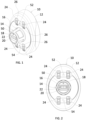
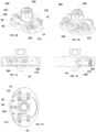
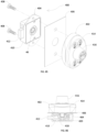
- Figures 1 and 2 show a first example of a lock assembly 10 suitable for use on cabinets, closets, lockers, drawers, doors, safes, and other items of furniture, as well as doors for human ingress and egress.
- the lock assembly 10 is what is known as 'shared use' mode. This mode is typical for, e.g., lockers in a gym, where lockers are not assigned to specific individuals, where different individuals may use the same locker each day, and where an individual must select an empty locker upon each visit.
- the user Prior to using the locker, the user must first set the unlocking combination, and when the user later returns to the locker and uses the unlocking combination to unlock and unlatch the lock assembly 10, the unlocking combination is erased, and the next user must set a new unlocking combination.
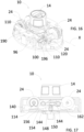
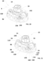
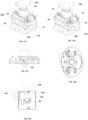
- the lock assembly 10 includes an outer housing 12 and a knob assembly 14 that can rotate relative to the outer housing 12.
- the knob assembly 14 includes a knob housing 16 having a front face 18, and an opening 20 in the front face 18 sized and shaped to receive a port 22.
- the lock assembly 10 also includes four rotatable dials 24, each of which includes indicia thereon, in this case the numbers 0-9. A portion of each rotatable dial 24 is visible and accessible through a respective opening 26 in the outer housing 12. A user may rotate the dials 24 to align a selected of the indicia in the openings 26 to a specific combination of numbers both to (a) set the combination that will unlock the lock assembly 10 and (b) to unlock the lock assembly 10, which will allow the user to rotate the knob assembly 14.
- the port 22 may be used to receive power and data, as will be described below.
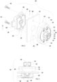
- Figs. 3 and 4 depict the lock assembly 10 combined with a standard deadbolt assembly 28 to form a combination lock 30, with the combination lock 30 mounted to a panel 32.
- the deadbolt assembly 28 includes a deadbolt housing 34 that include two mounting through holes 36.
- the panel 32 may be a door on an item of furniture, as described above, and includes two mounting holes 38 and a shaft hole 40 to form of a standard three-hole locker prep.
- Two threaded fasteners 42 mount the deadbolt assembly 28 and the lock assembly 10 both to the panel 32 and to each other by extending through the mounting holes 36 of the deadbolt housing 34 and through the mounting holes 38 of the panel 32 into internally threaded holes (not shown) in the lock assembly 10.
- the lock assembly 10 includes a drive shaft 44 extending out its rear side, best seen in Figure 4 .
- the deadbolt assembly 28 includes a shaft receiver 46 that accepts the shaft 44.
- the deadbolt assembly 28 further includes a deadbolt 48 that is coupled to the shaft receiver 46.
- a user may rotate the knob assembly 14, which rotates the shaft 44 and shaft receiver 46.
- the shaft receiver 46 shifts the deadbolt 48 laterally relative to the deadbolt housing 34 between a bolted position in which the deadbolt 48 extends out from the deadbolt housing 34, and an unbolted position, where the deadbolt 48 is retracted at least partially within the deadbolt housing 34.
- Disposed on the front face 18 is an arrow 50.
- the outer housing 12 includes a locked symbol 52 and an unlocked symbol 54.
- the lock assembly 10 is configured such that the deadbolt 48 is extended out of the deadbolt housing 34 in the bolted position where the combination lock 30 can secure the panel 32 on, e.g., an item of furniture, in a closed position.
- the knob assembly 14 is rotated, and the arrow 50 no longer points to the locked symbol 52 but instead points to the unlocked symbol 54, the deadbolt 48 is pulled within the deadbolt housing 34 to an unbolted position, and the panel 32 may be opened relative to the item of furniture, closet, door frame, etc.
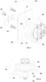
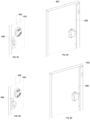
- a second example of a lock assembly 60 is shown assembled to a cam blade 62 to form a second example of a combination lock 64.
- the lock assembly 60 is assembled to a panel 68 via two threaded fasteners 70 extending through two through holes 72 in the panel 68.
- the lock assembly 60 includes a shaft housing 74 extending away from the backside of the lock housing 66 through a shaft hole 76 in the panel 68.
- a shaft (not seen in this embodiment) extends through the shaft housing 74, and a threaded hole is accessible on the back side of the shaft.
- the cam blade 62 is attached to the shaft via a screw 78.
- the shaft hole 76 in the panel 68 may include flat sides 80.
- the lock assembly 60 may be used to replace a conventional mechanical cam lock, and the shaft hole 76 in the panel 68 may have these flat sides 80 based on the prior cam lock usage. To convert, the user will only need to add the two through holes 72.
- the combination lock 64 of Figs. 5 & 6 operates similarly to that of the combination lock 30 of Figs. 3 & 4 except that the cam blade 62 is rotated between a latched position shown in Figs. 5 and 6 and an unlatched position in which the cam blade 62 would be in a horizontal position.
- This disclosure discloses locking elements including a deadbolt 48 and a cam blade 62, although other locking elements, such as retractable slam latches, are known in the art and can be employed. Moreover, this disclosure refers to a 'latched position.' This term should be understood broadly and encompasses all types of locking elements, such as the deadbolt 48, the cam blade 62, slam latches, and the like, in a position that can maintain the panel 32 in a closed position, and an "unlatched position" where the locking element does not impede opening and closing of the panel. Moreover, in most instances, the combination lock 30 will be station on a door panel which pivots to provide access to, e.g., an interior of an item of furniture. The combination lock 30 could also be located on the frame, with the door panel being pivoted relative to the frame.
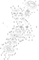
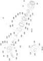
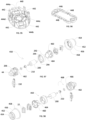
- Fig. 7 the internal components of the lock assembly 10 are shown, which are generally enclosed by the outer housing 12, the knob housing 16, and a back plate 90.
- the outer housing 12 includes a knob opening 92 and the four dial openings 26 through which the rotatable dials 24 are accessible.
- the direction “up” shall refer to the direction along axis Y toward the front face 18.
- the direction “in” or “inwardly” shall refer to a direction towards the axis X
- a direction “out” or “outwardly” shall refer to a direction away from the axis X.
- each side plate 96 includes a lug 100 extending inwardly that interacts with the knob assembly 14, as will be described in more detail later.
- Each side plate 96 includes a pair of mounting holes 102 which receive ends of two axles 104. Caps 106 capture each end of each axle 104.
- the back plate 90 includes two pairs of axle mounts 108 in which the caps 106 are supported.
- Each toggle plate 110 Disposed on each of the axles 104 are two toggle plates 110, which are shown in detail in Fig. 7a .
- Each toggle plate 110 includes a circular outer surface 112, a flat surface 114, and a notch 116 in the flat surface 114.
- Each toggle plate 110 also includes a ten-point spur gear 118 extending inwardly toward middle axis X.
- Also disposed on each axle 104 is a pair of toggle plate springs 120, a pair of washers 122, and two of the rotatable dials 24 that are biased away from the toggle plates 110 by the toggle plate springs 120.
- Each rotatable dial 24 forms an internal ten point ring gear 124 that is complementary to each ten point spur gear 118.
- each rotatable dial 24 can engage a respective toggle plate 110 is any of ten distinct rotational orientations, corresponding to the numerical indicia 0-9 on the rotatable dials.
- Both axles 104 include shoulders 126 that locate the washers 122 laterally due to the force of the inward push of the toggle plate spring 120.
- the rotatable dials 24 are located laterally by the openings 26, and the washers 122 bear the force of the springs 120, allowing the rotatable dials 24 to rotate freely.
- Each rotatable dial 24 includes on its inward side an eccentric cam 128 that may be used to rotationally orient the rotatable dial 24.
- the surface of the eccentric cam 128 is closest to the axle 104 on a side opposite the number "0" on the rotatable dial 24, the significance of which will be described below.
- Each return block 132 is pivotably mounted in the mounts 130.
- Each return block 132 includes a pair of pins 134 that extend through openings in the mounts 130 such that the return blocks 132 can be pivoted about the pins 134.
- Each of the return blocks 132 include a follower 136. As will be described in more detail later, each follower 136 interacts with the knob assembly 14 as it is rotated that forces the followers 136 up and down in a barrel cam configuration and cause the return blocks 132 to pivot about the pins 134.
- Each return block 132 further includes a pair of drivers 138 that interact with the eccentric cams 128.
- a pair of lock plates 140 are disposed on posts 142 of the back plate 90, and a spring plate 144 is disposed in recesses 146 of the back plate 90.
- the lock plates 140 each include a lock block 148.
- the knob assembly 14 includes a lock bar 150, and when the lock assembly 10 is in the locked position, the lock blocks 148 abut the ends of the lock bar 150 and prevent rotation of the knob assembly 14.
- the lock blocks 148 also include return ramps 152 which allow the user to rotate the knob assembly 14 in the counterclockwise direction, and the lock bar 150 rides up the return ramps 152 as it is rotated, and then drops back down behind the lock blocks 148 to the locked position.
- the lock plates 140 further each include a spring tab 154, and the spring plate 144 includes a pair of leaf springs 156 which bear against the spring tabs 154 and bias the lock plates 140 up and away from the back plate 90. Also disposed on each lock plate 140 is a pair of bearing faces 158 and each bearing face 158 includes a ridge 160.
- the circular outer surface 112 of the toggle plates 110 typically bear against the bearing faces 158 and force the lock plates 140 down toward the back plate 90.
- the flat surfaces 114 of the toggle plates 110 are all face the bearing face 158, which allows the lock plates 140 to be pushed up and away from the back plate 90 by the leaf springs 156.
- the toggle plate springs 120 push the toggle plates 110 away from middle axis X, and the notches 116 of the toggle plates 110 then slide onto the ridges 160. In this position the toggle plates 110 are positively maintained, and they are displaced from the rotated dials 24, which may be rotated independently from the toggle plates 110.
- the spring plate 144 includes a four dial springs 162. Each dial spring 162 bears against the back side of one of the rotatable dials 24 and specifically against the number opposite the number showing in the opening 26. The surface of each rotatable dial 24 for each number is substantially flat, and so the dial springs 162 bear against flat surfaces, causing each number to 'click' into place as the user rotates the rotatable dials 24.
- the spring plate 144 includes two stands 164 that set the spring plate 144 a distance up and away from the back plate 90. It further includes two locator tabs 165 that help to locate the position of the spring plate 144 relative to the back plate 90.
- the back plate 90 may be mounted to the outer housing 12 via four screws 166.
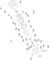
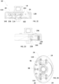
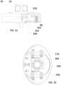
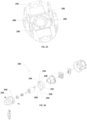
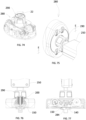
- Figs. 8 and 9 exploded views of the knob assembly 14 are shown. Disposed within the knob housing 16 and accessible through the knob opening 20 is the port 22 with port openings 170. Under the port 22 is a circuit board 172 having contacts 174 that extend through the port openings 170. Also disposed on the circuit board 172 are, e.g., one or more processors and memory. The contacts 174 may receive data and power from an electronic key employed by an end user and can transmit them to the circuit board 172.
- the circuit board 172 is mounted to a cap 176.
- the cap 176 includes posts 178 and openings 180.
- the circuit board 172 is mounted on the posts 178.
- the knob housing 16 includes internal pins 182 (shown in Fig. 9 ) that extend downwardly and engage the openings 180 on the cap 172 to affix the cap 176 to the knob housing 16 such that rotation of the knob housing 16 causes rotation of the cap 176.
- the cap 176 includes two pair of tabs 184 extending downwardly as well as two fingers 186 extending downwardly, and each finger 186 includes a threaded hole 188.
- a control ring 190 Disposed beneath the cap 176 is a control ring 190 that is biased away from the cap 176 by a cap spring 192.
- the control ring 190 includes two pair of slots 194 that receive the tabs 184 of the cap 176 which transmit rotation of the cap 176 to the control ring 190.
- the tabs 184 of the cap 176 are slightly narrower than the slots 194 of the control ring 190, such that when rotating from the latched position to the unlatched position, the knob housing 16 will rotate slightly before rotating the control ring 190.
- the control ring 190 further includes a pair of recessed ramps 196 and a pair of angled slots 198 that cooperate with the lugs 100 of the side plates 96 during operation which allow the side plates 96 to shift toward and away from middle axis X, as will be discussed in more detail.
- An electronically operated linear solenoid actuator 200 includes a wire 202 soldered to the circuit board 172 and is in communication with the circuit board 172.
- the actuator 200 includes a shaft 204 that translates linearly in and out.
- the knob assembly 14 includes a drive module 206 having a cylinder 208 and the drive shaft 44. Disposed within the cylinder 208 is the lock bar 150, a lock bar spring 210, and a clip 212 disposed on a circumferential recess 214 in the actuator shaft 204.
- the lock bar 150 is disposed on the actuator shaft 204 in between the clip 212 and the spring 210, and the spring 210 biases the lock bar 150 down, away from the knob housing 16.
- the lock bar 150 is shiftable between two positions toward and away from the knob housing 16. For assembly, the lock bar 150 is inserted laterally into the cylinder 208 through entry hole 216.
- the lock bar 150 includes exterior portions 218 that, as can be best seen in Fig. 7 , extend outside of the cylinder 208.
- the cylinder 206 further includes a pair of recessed through holes 220, a pair of screws 222, and a pair of slots 224.
- the fingers 186 of the cap 176 are disposed in the slots 224, and the screws 222 are screwed into the threaded holes 188 of the cap 176 to secure the cap 176 to the drive module 206.
- a groove forming a barrel cam slot 226 is disposed on the outer surface of the cylinder 208, and the followers 136 of the return block 132 are disposed in the cam slot 226. As the cylinder 208 is rotated, the followers 136 track within the cam slot 226 and are displaced towards and away from the knob housing 16. As mentioned earlier, this results in the pivoting of the return blocks 132 about the pins 134.
- the drive module 206 includes a knob bearing face 228 and drive cylinder 230.
- the back plate 90 includes a support face 232 and circular opening 234. When assembled, the bearing face 228 bears on the support face 232 to capture the knob assembly 14 within the outer housing 12, and the drive cylinder 230 extends through the circular opening 234.
- the knob assembly 14 further includes a stopper 236, and the back plate 90 include a stopper slot 238. The action of the stopper 236 sliding within the stopper slot 238 limits the rotation of the knob assembly 16 to approximately 180° of rotation between the latched position and the unlatched position.
- the back plate 90 further includes a pair of locator recesses 240 in which the locator tabs 165 of the spring plate 144 are disposed to help locate the spring plate 144.
- the knob bearing face 228 of the knob assembly 14 further includes a pair of ramped gaps 242 on opposite sides. When the knob assembly 14 is in the latched position and the unlatched position, the ramped gaps 242 of the bearing face 228 are disposed over the stands 164 of the spring plate 144, allowing the spring plate 144 to rise, which causes the dial springs 162 to bear on the rotatable dials 24.
- the knob assembly 14 is in a position where the arrow 50 is pointing toward the unlocked symbol 54, corresponding to the unlatched position, e.g. the position where the deadbolt 48 is retracted into the deadbolt housing 34 (see, e.g., Figs. 3 and 4 ), or the cam latch 62 is oriented horizontally, and the user is able to open and close the panel 32 to which the lock 30 is attached.
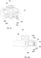
- the lock assembly 10 is shown with the outer housing 12 and the back plate 90 in section, and with one of the rotatable dials 24 and toggle plates 110 removed for clarity.
- the followers 136 of the return block 132 are disposed in the cam slots 226 of the drive module 206. In this position, the followers 136 are disposed toward the knob housing 16, thus pivoting the drivers 138 about the pins 134 down from the eccentric cams 128.
- the toggle plates 110 are all oriented with their flat surfaces 114 and notches 116 toward the back plate 90, such that the notches 116 of the toggle plates 110 are disposed within the ridges 160 of the lock plate 140. This prevents the toggle plates 110 from rotating.
- the lock springs 156 of the spring plate 144 press against the spring tabs 154 of the lock plates 140 and press the lock plates 140 up toward the knob housing 16. In this manner, the lock blocks 148 are shifted toward the knob housing 16 to an unlocked position and do not impede the rotation of the lock bar 150, and the user is able to rotate the knob assembly 14.
- the stands 164 of the spring plate 144 are disposed under the gaps 242 of the drive cylinder 230. See Figs. 14 and 14a .
- the spring plates 144 rise toward the knob housing 16, and the dial springs 162 bear against the rotatable dials 24 to "click" them into place as they rotate such that a selected number is visible within the opening 26.
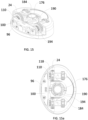
- the cap 176 and the control ring 190 are shown in cross section, and the tabs 184 are disposed in the slots 194.
- the knob assembly 14 In the position shown in Figs. 12-15 , the knob assembly 14 has been rotated fully to the unlatched position. Because the slots 194 are slightly wider than the tabs 184, the knob assembly 14 may be rotated a full 180 degrees with a slightly less than 180 degree rotation of the control ring 190. An end user may be more comfortable with a full 180 degree rotation.
- the lock assembly 10 is shown in a subsequent position where the lock assembly 10 is still in the unlatched position, and the user has rotated the rotatable dials 24, and the eccentric cams 128 along with them, to set an unlock code.
- the user has set the unlock code of the rotatable dials 24 to 1-2-3-4.
- the knob assembly 14 has not been rotated relative to the position shown in Figs. 12-15 , and so the control ring 190 continues to force the side plates 96 away from middle axis X, and the toggle springs 120 continue to force the toggle plates 110 to be disengaged from the rotatable dials 24. Accordingly, in this position, rotation of the rotatable dials 24 does not rotate the toggle plates 110.
- the toggle plates 110 continue to be in the position where the flat sides 114 face the locks plates 140, and so the lock plates 140 are forced up toward the knob assembly 14 by the lock springs 156 of the spring plates 144 bearing against the spring tabs 154 of the lock plates 140.
- the lock blocks 148 of the lock plate 140 therefore do not block rotation of the lock bar 150, and the spring plate 144 continues to be elevated away from the back plate 90, such that the dial springs 162 continue to bear against the rotatable dials 24, and the selected indicia are "clicked" into place when rotating the rotatable dials 24.
- this initial rotation of the knob assembly 14 includes the rotation of the cap 176
- the lugs 100 of the side plates 96 are disposed in the recessed ramps 196 of the control ring 190.
- the control ring 190 is rotated, and the lugs 100 force the control ring 190 up towards the knob housing 16 due to the recessed ramps 196 riding up the lugs 100 and against the bias of the cap spring 192.
- Figs. 21-24 the user has continued to rotate the knob assembly 14 in the counterclockwise direction.
- the ramping action of the lugs 100 in conjunction with the recess ramps 196 has caused the control ring 190 to be forced up toward the knob assembly 14 and above the lug 100.
- the side plates 96 and the lugs 100 then shift inward toward middle axis X underneath the control ring 190 under the force of the side plate springs 98.
- the side plates 96 push the toggle plates 110 toward middle axis X into engagement with the rotatable dials 24, with the spur gears 118 of the toggle plates 110 setting in the ring gears 124 of the rotatable dials 24.
- the notches 116 of the toggle plates 110 are no longer disposed over the ridges 160 of the lock plate 140, they have been shifted to the bearing surfaces 158, and the toggle plates 110 may therefore be rotated. In this position, the flat surfaces 114 of the toggle plates 110 still bear against the lock plate 140, such that the lock plate 140 continues to be shifted up. Because the toggle plates 110 engage with the rotatable dials 24 while the lock plate 140 is in the unlocking position, the user has set the unlocking code to be 1-2-3-4.
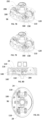
- Figs. 25-28 depict the scrambling function of the lock assembly 10.
- the cam slot 226 of the drive module 206 directs the followers 136 of the return blocks 132 down toward the back plate 90.
- the return blocks 132 pivot about their pins 134, causing the drivers 138 to shift in a direction up and away from the back panel 90 and against the eccentric cams 128 of the rotatable dials 24, thereby rotating each of the rotatable dials 24 into the 0-0-0-0 position and scrambling the rotatable dials away from the unlocking code to the generic 'all zeros' position.
- Rotation of the rotatable dials 24 here also rotates the toggles plates 110 such that the flat surfaces 114 no longer bear on the bearing faces 158 of the lock plates 140. Instead, the circular outer surface 112 of the toggle plates 110 bear on the bearing faces 158, thereby forcing the lock plates down toward the back plate 90 against the force of the spring plate 144 and into the locking position.
- the knob assembly 14 has been rotated a full 180° counterclockwise into the locked and latched position.
- the control ring 190 has been rotated to and past a position where the angled slots 198 are directly up above the lugs 100 (in the orientation of Fig. 29 ) of the side plates 96.
- the cap spring 192 forces the control ring 190 to drop down toward the back plate 90, and the lugs 100 are disposed within the angled slots 198 of the control ring 190.
- the cam slots 226 have directed the followers 136 of the return blocks 132 back away from the back panel 90 and the drivers 138 are again spaced from the eccentric cams 128.
- the lock bars 140 are in the locking position, as the knob assembly 14 is rotated from the position shown in Fig. 25 to the position shown in Fig. 29 , the lock bar 150 rides up the return ramps 152 of the lock plates 140 and against the bias of the lock bar spring 210. Upon fully passing the return ramps 152, the lock bar 150 drops in behind the lock blocks 148 of the lock plate 140.
- the lock blocks 148 prevent rotation of the knob assembly 14 in the clockwise direction, and the interaction of the stopper 236 and the stopper slot 238 prevent further rotation of the knob assembly 14 in the counterclockwise direction. In this position, the ramped gaps 242 have again come to be disposed over the stands 164 of the spring plate 144, allowing the dial springs 162 to raise up again and bear against the rotatable dials 24 to again 'click' them into place.
- the rotational travel of the control ring 190 from the recessed ramps 196 to the angled slots 198 may be approximately 160 degrees. Accordingly, the slots 194 of the control ring 190 are wider than the tabs 184 of the cap 176.
- the first approximately 20 degrees of rotational travel of the knob assembly 14 is simply the tabs 184 sliding within the slots 194 of the control ring 190, with no movement of the control ring 190. See, in particular, Fig. 15a . Once the first 15 degrees have been met, the tabs 184 reach the other side of the slots 194 and being to cause rotation of the control ring 190. See, in particular, Figs. 24 and 32 .
- Figs. 33-36 the beginning of the process of unlocking and unlatching the lock assembly 10 is described.
- the user has rotated the rotatable dials 24 back to the unlocking code 1-2-3-4.
- the side plates 94 continue to be shifted towards middle axis X, thereby keeping the toggle plates 110 engaged with the rotatable dials 24.
- the toggle plates 110 are rotated back to a position where their respective flat surfaces 114 are now bearing against the bearing faces 158 of the lock plates 140.
- This allows the lock plates 140 to shift upwardly towards the knob assembly 14, and thus the lock blocks 148 of the lock plates 140 do not impede the rotation in the clockwise direction of the lock bar 150.
- the lock plates 140 are biased in the up direction due to the lock spring 156 pushing against the spring tabs 154.
- the lock bar 150 is biased in the down position by the lock bar spring 210, and the lock assembly 10 is in the unlocked position.
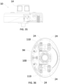
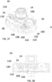
- the user has begun to rotate the knob assembly 14 in the clockwise direction to unlatch the lock assembly 10.
- the lugs 100 of the side plates 96 ride up the angled slots 198 of the control ring 190 until they ride on the outer surface of the control ring 190. This pushes the side plates 96 in a direction away from middle axis X and allows the toggle plate springs 120 to push the toggle plates 110 in a direction away from middle axis X and to disengage the spur gears 118 from the ring gears 124 of the rotatable dials 24.
- the toggle plates 110 are shifted, the notches 116 of the of the toggle plates 110 slide over and are disposed on the ridges 160 of the lock plates 140. This secures the toggles plates 110 in the unlocking position, while the rotatable dials 24 are free to rotate relative to the toggle plates 110.
- the knob assembly 14 is rotated, the stands 164 of the spring plate 144 are no longer underneath the ramped gaps 242 of the drive cylinder 230, and the knob bearing face 228 presses down on the stands 164, thereby forcing the dial springs 162 away from the rotatable dials 24 and allowing the rotatable dials 24 to rotate freely.
- the lock springs 156 continue to bias the lock plates 140 in the up positions.
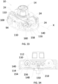
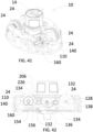
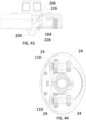
- Figs. 41-44 the user continues turning the knob assembly 14 clockwise. In this position, the lock assembly 10 scrambles the rotatable dials 24 similarly to the process shown in Figs. 25-28 .
- the knob bearing face 228 continues to press down on the stands 164, and the cam slots 226 of the drive module 206 drive the followers 136 of the return blocks 132 back toward the back plate 90.
- the return blocks 132 pivot about their pins 134, such that the drivers 138 bear against the eccentric cams 128 of the rotatable dials 24.
- the force exerted by the drivers 138 against the eccentric cams 128 causes the rotatable dials 24 to rotate such that the rotatable dials are rotated back to the 0-0-0-0 position, as best seen in Fig. 44 .
- the toggle plates 110 continue to be mounted over the ridges 160 of the lock plate 140 and held fast while the rotatable dials 24 are rotated, and lock spring 156 continue to press against the spring tabs 154 of the lock plates 140, thereby maintaining the lock plates 140 in the up, unlocked position.
- a user may set the lock code and place the lock into the locked and bolted position shown in Figs. 29-32 , but then the user may forget the lock code to unlock the locking assembly 10.
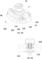
- an administrator may implement an electronic key 250 to unlock and unlatch the locking assembly 10. As shown in Figs. 45-48 and Fig. 8 , the administrator may place the electronic key 250 into the opening 20 and against the port 22 and contacts 174 to provide data and power to the circuit board 172. If the proper credential is supplied, the electronics on the circuit board 172 may direct the solenoid actuator 200 to actuate, and the actuator 200 may retract the shaft 204 thereby lifting the lock bar 150.
- the lock bar 150 is then above the lock blocks 148 of the lock plates 140, and the knob assembly 14 may be rotated to the unlatched position.
- the toggle plates 110 remain in position with their respective circular outer surfaces 112 against the bearing surfaces 158 of the lock plates 140, and the notches 116 not in alignment with the ridges 160, pressing the lock plates 140 down.
- Figs. 49 and 50 the administrator has rotated the knob assembly fully to the unlatched position.
- the administrator has removed the electronic key 250, the solenoid 200 is no longer energized, and the lock bar spring 210 has biased the lock bar 150 downwardly.
- the notches 116 will align with the ridges 160, and the toggle plate springs 120 will force the toggle plates 110 away from middle axis X over the ridges 160, and the toggle plates will disengage from the rotatable dials 24.
- the lock assembly 10 will be in the position shown in Fig. 12 , ready for the user to re-set the locking code and lock the lock assembly 10.
- a third example of a lock assembly 260 is disclosed showing a mechanical key override rather than an electronic key override.
- the lock assembly 260 includes a pin tumbler lock 262 having an output shaft 264 and ramp 266.
- a lock bar 268 is disposed on the shaft 264 and biased downwardly by a lock bar spring 270.
- the lock bar 268 is similar in structure to the lock bar 150, except that the lock bar 268 includes a projection 272 that engages with the ramp 266. If the user forgets their combination, an administrator can insert a mechanical key 274 into the tumbler lock 260 and rotate the key 274 a half turn.
- a fourth example of a lock assembly 280 is depicted.
- the lock assembly 280 is configured to be in 'assigned use' mode.
- the unlocking combination is set and in normal usage the unlocking combination is not changed by an end user. Instead, changing the unlocking combination requires application of a manager key.
- Assigned use can be useful in settings such as school lockers, where the student uses the same combination for the entire school year, and the school facilities manager will maintain control over the manager key.
- the operation is different than the first embodiment (again known as 'shared use'), which again requires the user to set the unlocking combination with each use and allows for different users to use the lock.
- the lock assembly 280 has a slightly different construction. The same components, however, from the initial embodiment retain the same reference numerals.
- the back plate 282 includes a pair of stoppers 284 each having a blocking face 286. As will be seen, the blocking faces 286 limit rotation of the lock bar 150 in this embodiment and prevents an end user from altering the unlocking code.
- the knob assembly 290 is generally similar to the knob assembly 14 of the first embodiment, with a slightly modified control ring 292 and a lack of a cap spring 192.
- the control ring 292 includes two projections 294 extending downwardly, each projection 294 including a ramp 296 and a block 298 opposite the ramp 296.
- the projections 294 are disposed on a top face 300 of the drive module 206.
- the projections 294 space the control ring 292 from the drive module 206 to leave a gap therebetween.
- the lock assembly 280 is depicted in the locked and latched position.
- the rotatable dials 24 are set in the 0-0-0-0 position.
- the side plates 96 are disposed inwardly under the force of the side plate springs 98, with the lugs 100 disposed in a gap 302 between the control ring 262 and the drive module 206.
- the toggle plates 110 force the lock plates 140 downwardly, which prevents the lock bar 150 from rotating and thereby prevents the user from rotating the knob assembly 260.
- Figs. 61-64 the user has rotated the rotatable dials 24 to the unlocking code, 1-2-3-4. As in the previous embodiments, this aligns the flat surfaces 114 of the toggle plates 110 with the lock plates 140 and allows the lock plates 140 to rise up, thereby no longer impeding rotation of the lock bar 150 or the knob assembly 290.
- the user may rotate the knob assembly 290, which will rotate the drive shaft 44, as shown in Figs. 65-68 .
- the followers 136 of the return block 132 follow the cam slot 226 of the drive module 206 downwardly as in previous embodiments, thereby pushing the drivers 138 upwardly against the eccentric cams 128 of the rotatable dials 24.
- the lugs 100 of the side plates 96 remain disposed in the gap 302 between the control ring 292 and the drive module 206 under the force of the side plate springs 98, and the toggle plates 110 remain engaged with the rotatable dials 24.
- the drive shaft 44 has been rotated sufficiently such that the locking element, such as the deadbolt 48 or the cam blade 62 of the first two embodiments is retracted and the user is able to open the panel 32 to which the lock assembly 280 is attached.
- the lugs 100 remain in the gap 302, and the side plate 96 continue to be forced inwardly by the side plate springs 98. In other words, the lugs 100 have not reached the ramps 296 of the control ring 292.
- the stoppers 284 of the back plate 282 block further rotation of the lock bar 150, and therefore prevent the lugs 100 from reaching the ramps 296.
- the user simply rotates the knob assembly 290 back to the position of Figs. 57-60 . While the knob assembly 290 is rotated back to that position, the lock plates 140 will be in the down position the entire time, but similar to previous embodiments, the lock bar 150 will slide up the return ramps 152 of the lock plates 140 and drop in behind the lock blocks 148 into the locking position.
- the sideplates 96 are disposed inwardly with the lugs 100 in the gap 302, and the toggle plates 110 are engaged with the rotatable dials 24.
- the unlocking combination therefore, cannot be changed during normal use by the end user.
- Fig. 74 depicts the lock assembly 280 in the locked and latched position, with the user desiring to unlock the lock and unlatch the door.
- the user first applies the electronic key 250 to the port 22, which applies power and data to the lock assembly 280. If the data includes the correct credential, the actuator 200 is activated, and it lifts the lock bar 150 up and above the lock plate 140. The user is then able to rotate the knob assembly 290 in the clockwise direction.
- the lock bar 150 is above the stoppers 284, and therefore the stoppers 284 do not stop the rotation of the knob assembly 290, as in Figs. 71 and 72 , and the user may rotate the lock bar 150 past the stoppers 284.
- Figs. 78 the lock assembly is shown in the unlocked and unlatched position.
- the lock bar 150 has been rotated past the stoppers 284, and the lugs 100 of the side plates 96 have followed the ramp 296 of the control ring 292 away from middle axis X, thereby pushing the side plates 96 out.
- the administrator has removed the key 250, which causes the lock bar 150 to drop down.
- the end user has rotated the rotatable dials 24 a full turn which, at some point within the rotation, aligned the notches 116 of the toggle plates 110 with the ridges 160 of the lock plates 140, and the toggle plate springs 120 have forced the toggle plates 110 off the rotatable dials 24 and onto the ridges 160, placing the lock plates 140 in the unlocked up position and disengaged the toggle plates 110 from the rotatable dials 24.
- the user can then set the unlocking combination by rotating the rotatable dials 24.
- the user has selected 1-2-3-4 as the unlocking code.
- the user can re-lock the lock assembly 280 as in previous embodiments as shown in Figs. 82-84 .
- the user has rotated the knob assembly 290 back a half turn counterclockwise.
- the rotatable dials 24 have been scrambled, the lock plates 140 have been pushed down to the locking position, and the latch bar 150 has ridden up the return ramps 152 of the lock plates 140 and dropped behind the latch blocks 148 into the locked position.
- the administrator may unlock and unlatch the lock assembly 280 using the key 250 as shown in the processes of Figs. 45-48 and/or 74- 78, but upon opening the locker, the end user and administrator realize that they have opened another end user's lock and locker. This may happen, for example, where the end user has entered his or her own code, but the code is incorrect because he or she is accessing the wrong lock and locker, believing it to be his or hers.
- the administrator does not rotate the rotatable dials 24 a full turn as described above. Instead, the administrator simply pivots the knob assembly 290 back counterclockwise to the position shown in Fig. 74 .
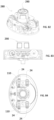
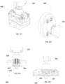
- the combination lock 400 is useful in lift-handle latch lockers.
- the combination lock 400 includes a lock assembly 402 and a bolt assembly 404 fastened together on a locker panel 406 using two bolts 408 in a standard three hole locker prep.
- the bolt assembly 404 includes a bolt housing 410 and a deadbolt 412 that shifts vertically between the latched position and unlatched positions, rather than retracting in and out of the bolt housing 410 as in previous embodiments.
- the deadbolt 412 as shown in Fig. 85 is in the latched position.
- the lock assembly 402 includes an outer housing 414 with an integral knob section 416. In contrast to previous embodiments, the knob section 416 of this embodiment does not rotate relative to the outer housing 414.
- the bolt assembly 404 further includes a shaft receiver 46 to which a gear 418 is attached.
- the gear 418 is engaged with the deadbolt 412 such that rotation of the shaft receiver 46 causes the gear 418 to lift or drop the deadbolt 412.
- lifting and dropping the deadbolt 412 causes the shaft receiver 46 to rotate.
- a spring 420 is mounted within the bolt housing 410 and biases the deadbolt 412 down to the latched position shown in Fig. 85 .
- the combination lock 400 is depicted mounted to a recessed panel 422 in a locker door 424.
- the locker door 424 includes a lift lever 426 attached to a shiftable frame 428 having a tab 430.
- the frame 428 is attached to a locker door latch within the locker door (not shown).
- the locker door 424 is latched shut.
- the locker door latch unlatches and allows the locker door 424 to be opened.
- the deadbolt 412 In the locked position of the combination lock 400, the deadbolt 412 is maintained in the down, latched position, and it blocks movement in the upward direction of the tab 430 and therefore the frame 428.
- the user cannot lift the lift lever 426 and the locker door 424 remains latched and closed. If the user places the combination lock 400 in the unlocked position, the deadbolt 412 is free to move upward, and the user can then lift the lift lever 426, raising the frame 428 and unlatching the locker door 424. Note that it may be possible for the knob section 416 to be rotatable as in the previous embodiments to latch and unlatch the locker door 424, but it would be difficult to rotate the knob section 416 to lift the frame 428 and door latch as those elements can be quite heavy.
- Figs. 91-94 depict a second example where the combination lock 400 is affixed to a locker door 432 with a flat face 434.
- operation is similar, and a user can place the combination lock 400 in the unlocked position, which frees the deadbolt 412 to be raised. The user can then pivot a lift lever 436, which raises a frame 438 and unlatches the locker door 432. If the combination lock 400 is in the locked position, the deadbolt 412 prevents the frame 438 from being lifted by the lift lever 436.
- a back plate 440 of the fifth embodiment is depicted.
- the back plate 440 is similar to the back plate 282 depicted in Fig. 55 with the following exceptions.
- the back plate 440 includes four ramped surfaces 442 each with a stoppers 444a, 444b, 444c, 444d.
- the stoppers 444c and 444d are the surfaces that maintain the combination lock 400 in the locked position, and stoppers 444a and 444b prevent the drive shaft 44 from rotating more than a quarter turn during normal operation.
- a lock plate 446 is further depicted.
- the lock plate 446 does not include lock blocks such as lock blocks 148 as are included on the lock plate 140.
- the lock plate 446 includes inward facing tabs 448. As will be described further, the tabs 448 sit under the lock bar 150 and, when the unlocking code is entered on the rotatable dials 24, the lock plate 446 is lifted as in previous embodiments, but here the tabs 448 lift the lock bar 150 above the stoppers 444c, 444d. The lock bar 150 does not extend past the tabs 448, and the lock plate 446 does not impede the rotation of the drive module 206 or the drive shaft 44 in this embodiment.
- a knob assembly 450 is depicted in Figs. 97 and 98 .
- the knob assembly 450 is generally similar to the knob assembly 290 of Fig. 56 with the following modifications.
- the knob assembly 450 includes a carrier 452 having an end wall 454, a side wall 456, and a rim 458. Unlike in previous embodiments, the side wall 456 of the carrier 452 resides underneath the knob section 416 of the outer housing 414, and only the end wall 454 is accessible when in use.
- the carrier 452, and the knob assembly 450 in general, is rotatable within the outer housing 414 by applying the key 250 to the port 22 and turning the key 250.
- the knob assembly 450 further includes a cap 460 and a cylinder 462.
- the carrier 452 is affixed to the cap 460.
- the cap 460 and cylinder 462 are not affixed to each other as in previous embodiments, but instead employ a type of lost motion linkage.
- the cap 460 includes a half turn stopper 464, and the cylinder 462 includes a quarter turn stopper 466.
- the set up shown in Figs. 97 and 98 is such that the cylinder 462 may be in the latched position.
- the cylinder 462 may be rotated a quarter turn in the clockwise direction 468 freely without the quarter turn stopper 466 engaging the half turn stopper 468.
- a quarter turn in the clockwise direction of the cylinder 462 corresponds to the unlatched position of the deadbolt 412.
- the deadbolt 412 can be rotated between the latched position and the unlatched position without rotating the cap 460 or the carrier 452.
- the half turn stopper 464 bears against the quarter turn stopper 466 and rotates it in the clockwise direction from the latched position to the unlatched position.
- Figs. 99-102 the combination lock 450 is in the locked position and the deadbolt 412 is in the latched position.
- the rotatable dials 24 are positioned such that the toggle plates 110 are pressing the lock plates 446 downwardly.
- the spring 210 within the knob assembly 450 is forcing the lock bar 150 downwardly and the stopper faces 444 of the back plate 440 prevent the cylinder 462 from being rotated.
- Fig. 101 depicts the positions of the quarter turn stopper 466 and the half turn stopper 464
- fig. 102 depicts the position of the shaft receiver 46, the gear 418, and the deadbolt 412, and its rack gear 470.
- the user has entered the unlocking code by rotating the rotatable dials 24.
- the toggle plates 110 allow the lock plates 446 to be lifted, and in this embodiment the lock plates 446 and their tabs 448 lift the lock bar 150 to a plane above the stoppers 444.
- the deadbolt 412 remains in the same latched position, and the quarter turn stopper 466 and the half turn stopper 464 also remain in the same position.
- Figs. 107-110 depict the next step where the user has lifted the lift lever 426 and placed the deadbolt 412 into the unlatched position.
- lifting of the deadbolt 412 causes the shaft receiver 46 to be rotated a quarter turn via the gears 470 and 418.
- This in turn causes the cylinder 462 to be rotated a quarter turn, and as shown in Fig. 109 , the quarter turn stopper 466 has been rotated a quarter turn.
- the lock bar 150 falls off the tabs 448 of the lock plate 446 and back down against the back plate 440, and the stoppers 444a, 444b, block rotation of the cylinder 462 more than a quarter turn.
- the rotatable dials 24 have been scrambled to a 0-0-0-0 position by the return blocks 132 pressing against the eccentric cams 128 of the rotatable dials 24, and the toggle plates 110 again press down on the lock plates 446.
- the key 250 can be rotated another quarter turn, to a full half turn, to set a new unlocking code, with the key 250 maintaining the lock bar 150 in the raised position.
- a cylindrical portion 472 of the gear 470 slides along the gear 418 of the deadbolt 412 to maintain the deadbolt 412 in the unlatched position without forcing it further upward. See Fig. 119 .
- the projections 294 of the control ring 292 push the side plates 96 laterally outward, which allows the toggle plates 110 to disengage from the rotatable dials 24 as described in earlier embodiments. The user can set the new unlocking code on the rotatable dials 24.
- the user can then begin to rotate the carrier 452 back.
- the side plates 92 will first shift back laterally inward, the toggle plates 110 will then reengage the rotatable dials 24 to set the unlocking code.
- the rotatable dials 24 are then scrambled as described previously by the return blocks 132.
- the half turn stopper 464 In the half turn return of the carrier 452, the half turn stopper 464 only contacts the quarter turn stopper 466 after a quarter turn has been made - there is a quarter turn of lost motion on the return trip.. In the second quarter turn of the key 250, the half turn stopper 464 engages the quarter turn stopper 466 and forces the rotation of the cylinder 462 and the shaft receiver 46. The cylindrical portion 472 of the gear 418 slides along the gear 470 of the deadbolt 412. After the half turn of the knob is complete, the carrier 452 is back in the original position.
Landscapes
- Physics & Mathematics (AREA)
- Electromagnetism (AREA)
- Lock And Its Accessories (AREA)
Applications Claiming Priority (2)
| Application Number | Priority Date | Filing Date | Title |
|---|---|---|---|
| US18/533,198 US12044038B2 (en) | 2019-05-30 | 2023-12-08 | Combination lock with override key |
| US18/968,904 US20250122751A1 (en) | 2019-05-30 | 2024-12-04 | Combination Lock with Override Key |
Publications (1)
| Publication Number | Publication Date |
|---|---|
| EP4567227A1 true EP4567227A1 (fr) | 2025-06-11 |
Family
ID=93705014
Family Applications (1)
| Application Number | Title | Priority Date | Filing Date |
|---|---|---|---|
| EP24217829.1A Pending EP4567227A1 (fr) | 2023-12-08 | 2024-12-05 | Serrure à combinaison avec clé de surpassement |
Country Status (1)
| Country | Link |
|---|---|
| EP (1) | EP4567227A1 (fr) |
Citations (16)
| Publication number | Priority date | Publication date | Assignee | Title |
|---|---|---|---|---|
| US5886644A (en) | 1996-03-12 | 1999-03-23 | Security People, Inc. | Programmable digital electronic lock |
| US5894277A (en) | 1996-03-12 | 1999-04-13 | Security People, Inc. | Programmable digital electronic lock |
| US6877345B1 (en) | 2003-08-05 | 2005-04-12 | The Eastern Company | Combination and key operated padlock with indicator |
| US7444844B1 (en) | 2007-12-18 | 2008-11-04 | Aba Ufo International Corp. | Dual-mode lock for lockers |
| US20080307838A1 (en) | 2007-06-13 | 2008-12-18 | Sinox Co., Ltd. | Combined key and combination resettable lock |
| US7628047B2 (en) | 2007-10-25 | 2009-12-08 | Aba Ufo International Corp. | Compound lock |
| US20090301147A1 (en) | 2008-06-06 | 2009-12-10 | Ping Jan Yang | Compound lock |
| US7958757B1 (en) | 2010-03-11 | 2011-06-14 | Aba Ufo International Corp. | Cam lock for a cabinet |
| US8161781B2 (en) | 2008-06-17 | 2012-04-24 | Security People, Inc. | Electronic locker lock |
| US8234891B2 (en) | 2006-11-15 | 2012-08-07 | Compx International Inc. | Combination cam lock with improved combination change mode |
| US8316675B2 (en) | 2011-01-21 | 2012-11-27 | Yao Kun Yang | Dual locking device |
| US8769999B2 (en) | 2007-06-21 | 2014-07-08 | Master Lock Company Llc | Combination lock |
| US9121199B2 (en) | 2010-05-25 | 2015-09-01 | DigiPas USA, LLC | Electronic combination lock |
| EP2942457A1 (fr) * | 2014-05-08 | 2015-11-11 | W&F Locks OHG | Dispositif de fermeture |
| US9222283B1 (en) | 2015-03-19 | 2015-12-29 | Digilock Asia Ltd. | Combination lock with override key |
| US20210079692A1 (en) * | 2019-05-30 | 2021-03-18 | Digilock Asia Ltd. | Combination Lock with Electronic Override Key |
-
2024
- 2024-12-05 EP EP24217829.1A patent/EP4567227A1/fr active Pending
Patent Citations (16)
| Publication number | Priority date | Publication date | Assignee | Title |
|---|---|---|---|---|
| US5894277A (en) | 1996-03-12 | 1999-04-13 | Security People, Inc. | Programmable digital electronic lock |
| US5886644A (en) | 1996-03-12 | 1999-03-23 | Security People, Inc. | Programmable digital electronic lock |
| US6877345B1 (en) | 2003-08-05 | 2005-04-12 | The Eastern Company | Combination and key operated padlock with indicator |
| US8234891B2 (en) | 2006-11-15 | 2012-08-07 | Compx International Inc. | Combination cam lock with improved combination change mode |
| US20080307838A1 (en) | 2007-06-13 | 2008-12-18 | Sinox Co., Ltd. | Combined key and combination resettable lock |
| US8769999B2 (en) | 2007-06-21 | 2014-07-08 | Master Lock Company Llc | Combination lock |
| US7628047B2 (en) | 2007-10-25 | 2009-12-08 | Aba Ufo International Corp. | Compound lock |
| US7444844B1 (en) | 2007-12-18 | 2008-11-04 | Aba Ufo International Corp. | Dual-mode lock for lockers |
| US20090301147A1 (en) | 2008-06-06 | 2009-12-10 | Ping Jan Yang | Compound lock |
| US8161781B2 (en) | 2008-06-17 | 2012-04-24 | Security People, Inc. | Electronic locker lock |
| US7958757B1 (en) | 2010-03-11 | 2011-06-14 | Aba Ufo International Corp. | Cam lock for a cabinet |
| US9121199B2 (en) | 2010-05-25 | 2015-09-01 | DigiPas USA, LLC | Electronic combination lock |
| US8316675B2 (en) | 2011-01-21 | 2012-11-27 | Yao Kun Yang | Dual locking device |
| EP2942457A1 (fr) * | 2014-05-08 | 2015-11-11 | W&F Locks OHG | Dispositif de fermeture |
| US9222283B1 (en) | 2015-03-19 | 2015-12-29 | Digilock Asia Ltd. | Combination lock with override key |
| US20210079692A1 (en) * | 2019-05-30 | 2021-03-18 | Digilock Asia Ltd. | Combination Lock with Electronic Override Key |
Similar Documents
| Publication | Publication Date | Title |
|---|---|---|
| US10851563B1 (en) | Combination lock with electronic override key | |
| US8555686B2 (en) | Mechanical pushbutton locking arrangements | |
| US12044038B2 (en) | Combination lock with override key | |
| CA2674105C (fr) | Cadenas a combinaisons | |
| US10487541B1 (en) | Combination lock with electronic override key | |
| US12110712B2 (en) | Combination lock | |
| GB1586114A (en) | Safes | |
| US6732664B2 (en) | Key and combination locking mechanism | |
| US4602491A (en) | Combination lock | |
| EP4567227A1 (fr) | Serrure à combinaison avec clé de surpassement | |
| US20250122751A1 (en) | Combination Lock with Override Key | |
| EP4567226A1 (fr) | Méthode de surpassement d'une serrure mechanique | |
| EP4567225A1 (fr) | Serrure à combinaison avec clé de surpassement | |
| HK40128779A (en) | Combination lock with override key | |
| US20240301721A1 (en) | Combination Lock with Override Key | |
| US20130239629A1 (en) | Lock with linearly operating latch | |
| US9890560B2 (en) | Locking apparatus | |
| HK40127965A (en) | Method of electronically overriding a mechanical lock | |
| HK40127964A (en) | Combination lock with override key | |
| US20080216531A1 (en) | Locking apparatus | |
| US9003844B2 (en) | Combination locks with improved code-changing features | |
| HK40127530A (zh) | 带超控钥匙的密码锁 | |
| CN101583771A (zh) | 组合挂锁 | |
| US3406545A (en) | Lock for locker doors and the like | |
| JPH0660544B2 (ja) | 符号錠装置 |
Legal Events
| Date | Code | Title | Description |
|---|---|---|---|
| PUAI | Public reference made under article 153(3) epc to a published international application that has entered the european phase |
Free format text: ORIGINAL CODE: 0009012 |
|
| STAA | Information on the status of an ep patent application or granted ep patent |
Free format text: STATUS: THE APPLICATION HAS BEEN PUBLISHED |
|
| AK | Designated contracting states |
Kind code of ref document: A1 Designated state(s): AL AT BE BG CH CY CZ DE DK EE ES FI FR GB GR HR HU IE IS IT LI LT LU LV MC ME MK MT NL NO PL PT RO RS SE SI SK SM TR |
|
| STAA | Information on the status of an ep patent application or granted ep patent |
Free format text: STATUS: REQUEST FOR EXAMINATION WAS MADE |
|
| 17P | Request for examination filed |
Effective date: 20251209 |
|
| RIC1 | Information provided on ipc code assigned before grant |
Ipc: E05B 13/10 20060101AFI20251227BHEP Ipc: E05B 37/00 20060101ALI20251227BHEP Ipc: E05B 37/12 20060101ALI20251227BHEP Ipc: E05B 47/00 20060101ALI20251227BHEP Ipc: E05B 47/06 20060101ALI20251227BHEP Ipc: E05B 65/02 20060101ALI20251227BHEP Ipc: E05B 15/00 20060101ALN20251227BHEP Ipc: E05C 1/06 20060101ALN20251227BHEP Ipc: E05C 3/04 20060101ALN20251227BHEP Ipc: G07C 9/00 20200101ALN20251227BHEP |
|
| GRAP | Despatch of communication of intention to grant a patent |
Free format text: ORIGINAL CODE: EPIDOSNIGR1 |
|
| STAA | Information on the status of an ep patent application or granted ep patent |
Free format text: STATUS: GRANT OF PATENT IS INTENDED |
|
| REG | Reference to a national code |
Ref country code: HK Ref legal event code: DE Ref document number: 40128779 Country of ref document: HK |
|
| INTG | Intention to grant announced |
Effective date: 20260212 |