EP4567236A1 - Tringlerie pour entraînement de protection contre l'incendie sans barrière - Google Patents
Tringlerie pour entraînement de protection contre l'incendie sans barrière Download PDFInfo
- Publication number
- EP4567236A1 EP4567236A1 EP24215441.7A EP24215441A EP4567236A1 EP 4567236 A1 EP4567236 A1 EP 4567236A1 EP 24215441 A EP24215441 A EP 24215441A EP 4567236 A1 EP4567236 A1 EP 4567236A1
- Authority
- EP
- European Patent Office
- Prior art keywords
- driver
- lock
- drive
- linkage
- output shaft
- Prior art date
- Legal status (The legal status is an assumption and is not a legal conclusion. Google has not performed a legal analysis and makes no representation as to the accuracy of the status listed.)
- Pending
Links
Images

Classifications
-
- E—FIXED CONSTRUCTIONS
- E05—LOCKS; KEYS; WINDOW OR DOOR FITTINGS; SAFES
- E05F—DEVICES FOR MOVING WINGS INTO OPEN OR CLOSED POSITION; CHECKS FOR WINGS; WING FITTINGS NOT OTHERWISE PROVIDED FOR, CONCERNED WITH THE FUNCTIONING OF THE WING
- E05F15/00—Power-operated mechanisms for wings
- E05F15/70—Power-operated mechanisms for wings with automatic actuation
- E05F15/72—Power-operated mechanisms for wings with automatic actuation responsive to emergency conditions, e.g. fire
-
- E—FIXED CONSTRUCTIONS
- E05—LOCKS; KEYS; WINDOW OR DOOR FITTINGS; SAFES
- E05F—DEVICES FOR MOVING WINGS INTO OPEN OR CLOSED POSITION; CHECKS FOR WINGS; WING FITTINGS NOT OTHERWISE PROVIDED FOR, CONCERNED WITH THE FUNCTIONING OF THE WING
- E05F1/00—Closers or openers for wings, not otherwise provided for in this subclass
- E05F1/08—Closers or openers for wings, not otherwise provided for in this subclass spring-actuated, e.g. for horizontally sliding wings
- E05F1/10—Closers or openers for wings, not otherwise provided for in this subclass spring-actuated, e.g. for horizontally sliding wings for swinging wings, e.g. counterbalance
-
- E—FIXED CONSTRUCTIONS
- E05—LOCKS; KEYS; WINDOW OR DOOR FITTINGS; SAFES
- E05F—DEVICES FOR MOVING WINGS INTO OPEN OR CLOSED POSITION; CHECKS FOR WINGS; WING FITTINGS NOT OTHERWISE PROVIDED FOR, CONCERNED WITH THE FUNCTIONING OF THE WING
- E05F15/00—Power-operated mechanisms for wings
- E05F15/60—Power-operated mechanisms for wings using electrical actuators
- E05F15/603—Power-operated mechanisms for wings using electrical actuators using rotary electromotors
- E05F15/611—Power-operated mechanisms for wings using electrical actuators using rotary electromotors for swinging wings
-
- E—FIXED CONSTRUCTIONS
- E05—LOCKS; KEYS; WINDOW OR DOOR FITTINGS; SAFES
- E05F—DEVICES FOR MOVING WINGS INTO OPEN OR CLOSED POSITION; CHECKS FOR WINGS; WING FITTINGS NOT OTHERWISE PROVIDED FOR, CONCERNED WITH THE FUNCTIONING OF THE WING
- E05F15/00—Power-operated mechanisms for wings
- E05F15/60—Power-operated mechanisms for wings using electrical actuators
- E05F15/603—Power-operated mechanisms for wings using electrical actuators using rotary electromotors
- E05F15/611—Power-operated mechanisms for wings using electrical actuators using rotary electromotors for swinging wings
- E05F15/63—Power-operated mechanisms for wings using electrical actuators using rotary electromotors for swinging wings operated by swinging arms
-
- E—FIXED CONSTRUCTIONS
- E05—LOCKS; KEYS; WINDOW OR DOOR FITTINGS; SAFES
- E05F—DEVICES FOR MOVING WINGS INTO OPEN OR CLOSED POSITION; CHECKS FOR WINGS; WING FITTINGS NOT OTHERWISE PROVIDED FOR, CONCERNED WITH THE FUNCTIONING OF THE WING
- E05F3/00—Closers or openers with braking devices, e.g. checks; Construction of pneumatic or liquid braking devices
- E05F3/22—Additional arrangements for closers, e.g. for holding the wing in opened or other position
- E05F3/224—Additional arrangements for closers, e.g. for holding the wing in opened or other position for assisting in opening the wing
-
- E—FIXED CONSTRUCTIONS
- E05—LOCKS; KEYS; WINDOW OR DOOR FITTINGS; SAFES
- E05Y—INDEXING SCHEME ASSOCIATED WITH SUBCLASSES E05D AND E05F, RELATING TO CONSTRUCTION ELEMENTS, ELECTRIC CONTROL, POWER SUPPLY, POWER SIGNAL OR TRANSMISSION, USER INTERFACES, MOUNTING OR COUPLING, DETAILS, ACCESSORIES, AUXILIARY OPERATIONS NOT OTHERWISE PROVIDED FOR, APPLICATION THEREOF
- E05Y2201/00—Constructional elements; Accessories therefor
- E05Y2201/20—Brakes; Disengaging means; Holders; Stops; Valves; Accessories therefor
- E05Y2201/214—Disengaging means
-
- E—FIXED CONSTRUCTIONS
- E05—LOCKS; KEYS; WINDOW OR DOOR FITTINGS; SAFES
- E05Y—INDEXING SCHEME ASSOCIATED WITH SUBCLASSES E05D AND E05F, RELATING TO CONSTRUCTION ELEMENTS, ELECTRIC CONTROL, POWER SUPPLY, POWER SIGNAL OR TRANSMISSION, USER INTERFACES, MOUNTING OR COUPLING, DETAILS, ACCESSORIES, AUXILIARY OPERATIONS NOT OTHERWISE PROVIDED FOR, APPLICATION THEREOF
- E05Y2201/00—Constructional elements; Accessories therefor
- E05Y2201/20—Brakes; Disengaging means; Holders; Stops; Valves; Accessories therefor
- E05Y2201/23—Actuation thereof
- E05Y2201/232—Actuation thereof by automatically acting means
- E05Y2201/234—Actuation thereof by automatically acting means direction dependent
-
- E—FIXED CONSTRUCTIONS
- E05—LOCKS; KEYS; WINDOW OR DOOR FITTINGS; SAFES
- E05Y—INDEXING SCHEME ASSOCIATED WITH SUBCLASSES E05D AND E05F, RELATING TO CONSTRUCTION ELEMENTS, ELECTRIC CONTROL, POWER SUPPLY, POWER SIGNAL OR TRANSMISSION, USER INTERFACES, MOUNTING OR COUPLING, DETAILS, ACCESSORIES, AUXILIARY OPERATIONS NOT OTHERWISE PROVIDED FOR, APPLICATION THEREOF
- E05Y2201/00—Constructional elements; Accessories therefor
- E05Y2201/60—Suspension or transmission members; Accessories therefor
- E05Y2201/622—Suspension or transmission members elements
- E05Y2201/624—Arms
-
- E—FIXED CONSTRUCTIONS
- E05—LOCKS; KEYS; WINDOW OR DOOR FITTINGS; SAFES
- E05Y—INDEXING SCHEME ASSOCIATED WITH SUBCLASSES E05D AND E05F, RELATING TO CONSTRUCTION ELEMENTS, ELECTRIC CONTROL, POWER SUPPLY, POWER SIGNAL OR TRANSMISSION, USER INTERFACES, MOUNTING OR COUPLING, DETAILS, ACCESSORIES, AUXILIARY OPERATIONS NOT OTHERWISE PROVIDED FOR, APPLICATION THEREOF
- E05Y2800/00—Details, accessories and auxiliary operations not otherwise provided for
- E05Y2800/25—Emergency conditions
- E05Y2800/252—Emergency conditions the elements functioning only in case of emergency
-
- E—FIXED CONSTRUCTIONS
- E05—LOCKS; KEYS; WINDOW OR DOOR FITTINGS; SAFES
- E05Y—INDEXING SCHEME ASSOCIATED WITH SUBCLASSES E05D AND E05F, RELATING TO CONSTRUCTION ELEMENTS, ELECTRIC CONTROL, POWER SUPPLY, POWER SIGNAL OR TRANSMISSION, USER INTERFACES, MOUNTING OR COUPLING, DETAILS, ACCESSORIES, AUXILIARY OPERATIONS NOT OTHERWISE PROVIDED FOR, APPLICATION THEREOF
- E05Y2900/00—Application of doors, windows, wings or fittings thereof
- E05Y2900/10—Application of doors, windows, wings or fittings thereof for buildings or parts thereof
- E05Y2900/13—Type of wing
- E05Y2900/132—Doors
Definitions
- the present invention relates to a linkage for driving a leaf of a door, window, or the like. Furthermore, the invention relates to a drive for a leaf of a door, window, or the like having said linkage.
- Door drives and their linkages can be designed in a variety of ways. Depending on the application and desired function, they can be fully automatic, semi-automatic, or have a freewheel function.
- a door drive that operates with an electromechanical motor and a closing spring.
- the drive has an output shaft that is connected to the leaf via a power-transmitting linkage with a sliding arm and slide rail.
- the closing spring ensures that the leaf is securely closed even in the event of a power failure.
- that the drive has a locking device that interacts with the closing spring and can be switched on/off. In the switched-on position, this locking device keeps the closing spring pretensioned, so that the leaf can be driven exclusively by the electromechanical motor or manually operated.
- the closing spring is released, so that the leaf closes under the action of the closing spring.
- the locking device can be released via a fire detector or similar device.
- the invention is therefore based on the object of creating a linkage for a drive and a drive for a leaf of a door, window, or the like, which, particularly in the event of a fire, allows barrier-free access while complying with the regulations for fire doors and, in particular, complies with the standards DIN 18263-4 and EN 17372 (for fire doors) as well as DIN 18040-1 and DIN 12217 (to ensure barrier-free doors).
- the linkage should be designed in such a way that existing drives can be easily retrofitted with the innovative linkage, thus ensuring a drive for a barrier-free fire door.
- a linkage for a drive for a leaf of a door, a window or the like comprising a linkage arm, wherein the linkage arm is configured to be mounted rotatably about the longitudinal axis of an output shaft, a driver which is configured to be connected in a rotationally fixed manner to the output shaft of the drive, and a lock which is configured to be movably arranged between a first position and a second position, wherein in the first position the lock is configured to prevent rotation of the linkage arm about the longitudinal axis relative to the driver (14) (so that the leaf can be driven at least in the opening direction) and wherein in the second position the lock is configured to enable rotation of the linkage arm about the longitudinal axis relative to the driver (so that the leaf can be moved freely at least in the closing direction).
- the innovative linkage ensures that the link arm is operatively connected to the drive's output shaft in the first locking position, as is usually the case during normal door operation. Since the lock prevents rotation of the link arm relative to the follower (more precisely, it prevents movement of the link arm in the circumferential direction around the longitudinal axis relative to the follower) in the first position, but allows absolute rotation of the link arm around the longitudinal axis, rotation of the link arm inevitably results in rotation of the follower, and thus rotation of the output shaft. In other words, in the first locking position, the link arm is operatively connected to the output shaft or drive.
- the rotation of the linkage arm in the opening direction of the sash is understood to mean a rotation of the linkage arm around its longitudinal axis in a direction that, if there is an active connection between the linkage and the sash, results in the sash opening.
- the rotation of the linkage arm in the closing direction of the sash is understood to mean a rotation of the linkage arm around its longitudinal axis in a direction that, if there is an active connection between the linkage and the sash, results in the sash closing.
- the linkage thus includes a lock which, depending on the position (in interaction with the driver), can activate or deactivate a freewheel.
- the disclosed linkage or drive allows the leaf of doors or the like to be opened without significant effort in emergency mode (second position of the lock). This function is particularly important for facilities with elderly, weaker, or physically disabled people, such as hospitals, nursing homes, or kindergartens.
- the linkage according to the invention can ensure that fire protection corridors can continue to be formed in the event of a fire by enabling the door to close safely.
- the linkage arm comprises a bolt
- the lock in the first position of the lock, the lock is configured to engage the bolt and (thereby) prevent a relative movement of the bolt (and thus of the linkage arm) in the direction of rotation about the longitudinal axis relative to the driver, and wherein in the second position of the lock, the lock is configured to release the bolt and (thereby) enable a relative movement of the bolt in the direction of rotation about the longitudinal axis relative to the driver.
- the lock and the bolt are preferably engaged, while in the second position, the lock releases the bolt.
- automatic operation can take place for a drive on which the linkage is arranged.
- the bolt could also be attached to the lock.
- the lock is arranged so as to be movable along the longitudinal axis of the output shaft between the first position and the second position.
- the lock is configured to be mounted axially displaceably (along the longitudinal axis) on the driver.
- the lock in the first position of the lock, is preferably not rotatable relative to the link arm about the longitudinal axis, and in the second position of the lock, the lock is rotatable relative to the link arm about the longitudinal axis (both in the opening direction and (at least temporarily) in the closing direction of the sash).
- the lock in the first position, is secured against rotation relative to the driver (preferably in a form-fitting manner, e.g., via a hexagon or spline).
- the lock, the driver, and the link arm are arranged rotationally fixed relative to one another.
- the driver is configured to precede the linkage arm in the direction of rotation around the longitudinal axis in the opening direction of the wing when the lock is in the second position.
- the lock in the second position thus enables movement of the link arm relative to the driver in the opening direction, free movement of the (door) leaf in the opening direction is ensured.
- a pedestrian does not have to press the leaf against the driver and thus the drive and possibly a closing spring.
- the lock is designed to allow rotation of the link arm around the longitudinal axis relative to the driver in the closing direction of the leaf, it can also be ensured that secure closing is guaranteed after any essentially resistance-free passage through the door or the like.
- the linkage further comprises an actuator configured to move the lock between the first position and the second position, preferably axially along the longitudinal axis of the output shaft.
- the actuator preferably has an electromagnet configured to move the lock between the first position and the second position using electromagnetic force.
- the actuator can be designed as an electric lifting magnet, which can, for example, raise and lower the lock axially along the output shaft.
- the actuator could actuate the lock using a motor, i.e., move it between the first and second positions.
- the actuator is preferably configured to be fixedly connected to a housing of the drive.
- the actuator is configured to be fixedly mounted on the housing of a drive unit of the drive, preferably centrally above the output shaft.
- the actuator is configured to be connected to a control device, preferably a control device of the drive, and to receive a control signal from the control device.
- the actuator is configured to move the lock into the first position and/or to hold it in the first position when the actuator receives a normal operating signal as a control signal, and/or the actuator is configured to move the lock into the second position and/or to hold it in the second position when the actuator receives an emergency operating signal as a control signal.
- the driver is configured to be moved into a start position by the output shaft of the drive when the actuator receives the emergency operation signal, wherein in the start position a movement of the linkage arm (or the bolt) in the direction of rotation around the longitudinal axis, in particular in the opening direction of the wing, is enabled relative to the driver.
- This provides the link arm (especially the bolt) with freedom of movement during emergency operation.
- movement of the link arm in the opening direction of the leaf can be enabled.
- This allows the door or similar to be opened during emergency operation without great effort, since the link arm, as long as it is freely movable relative to the driver, does not have to fight against the drive unit of the drive and possibly a mechanical energy storage device.
- the starting position specifies how far the door (or the link arm) can be opened without resistance.
- the starting position is preferably selected such that free running of the The rod arm covers an angle of at least 45°, preferably at least 70°, more preferably at least 90°, relative to the closed position of the rod arm in the direction of rotation around the longitudinal axis in the opening direction of the wing.
- the drive comprises a control device which is configured to provide a control signal to the actuator, wherein the drive can be operated in a normal operation and in an emergency operation, wherein in normal operation a normal operation signal is provided as a control signal and/or wherein in emergency operation an emergency operation signal is provided.
- the control device can be connected to the actuator via cabling, for example, but non-cabled communication is also conceivable.
- the actuator is configured to move the lock into the second position upon receipt of the emergency operation signal when the leaf is in the closed position, and in emergency operation when the leaf is in the closed position, the drive device is configured to move the driver into a start position via the output shaft, so that a movement of the bolt in the direction of rotation around the longitudinal axis relative to the driver is enabled.
- the movement of the lock to the second position and the movement of the driver to the start position occur simultaneously.
- the control device provides the emergency operation signal to the actuator and the drive device simultaneously.
- the drive preferably comprises a mechanical energy storage device which is designed to be charged in emergency operation when the leaf is in the closed position. wherein the mechanical energy storage device is connected to the output shaft of the drive device and the driver in emergency operation in such a way that the charging of the mechanical energy storage device causes the driver to move into the starting position.
- the mechanical energy storage device is typically a (closing) spring, which can be configured as a tension, compression, or torsion spring.
- a spring arrangement comprising multiple springs is also conceivable.
- the spring (or the mechanical energy storage device) is connected to the drive unit for driving purposes, at least in emergency operation. Tensioning the spring then causes the driver to move circumferentially around the longitudinal axis in the opening direction of the (door) leaf. Releasing the spring causes the driver to move in the opposite direction.
- the mechanical energy storage device is preferably designed to immediately begin discharging in emergency operation when the wing is opened, wherein the mechanical energy storage device is connected to the output shaft of the drive device and the driver in such a way that the discharging of the mechanical energy storage device causes the driver to move in the closing direction of the wing, so that the driver causes the wing to move towards the closed position via the rod or the pin of the rod.
- the spring in the case of a spring as an energy storage device, the spring is initially charged in emergency operation, whereby the driver is moved to the starting position, i.e., it is moved relative to the rod or its bolt in the opening direction of the leaf or door.
- the rod or its bolt are not affected by this movement, i.e., the energy storage device can be charged in the closed position of the door. Opening the door causes the spring to relax and thus a movement of the driver in the closing direction and towards the rod or its bolt.
- the rod or bolt is freely movable in the opening direction of the leaf or door. In this respect, the leaf is in freewheeling mode during this period.
- the rod or bolt is driven in the closing direction by the driver and moved towards the closed position. In other words, the door is brought into the closed position via the driver (and the bolt).
- the drive preferably has a sensor unit for detecting the opening of the wing.
- the sensor unit can be designed as a micro switch, proximity sensor, or similar.
- the sensor unit can be configured to detect the opening angle of the sash relative to the closed position.
- the drive can be equipped with a trigger unit configured to provide an opening signal (and thus indicate the opening of the wing) upon detection of a leaf opening, in particular a predetermined (preferably adjustable) opening angle of the leaf or door relative to the closed position (during an opening movement of the leaf), by the sensor unit.
- the control device Upon receipt of the opening signal, the control device can be configured to (immediately) discharge the mechanical energy storage device.
- the drive is advantageously designed to be connected to an emergency power supply.
- the drive preferably has an uninterruptible power supply (UPS) to ensure emergency operation.
- UPS uninterruptible power supply
- the drive can also include one or more batteries to ensure emergency operation. Should the power supply (including batteries or the like) fail completely in an emergency, particularly in the event of a fire, the mechanical energy storage device is or will be operatively connected to the drive device. In this case, barrier-free access is no longer guaranteed, but at least the standards for fire doors are still met (extended emergency operation).
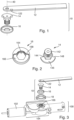
- Fig. 1 shows a first embodiment of the rod assembly according to the invention in an exploded view.
- the rod assembly designated by reference number 10 comprises a rod arm 12 with a bolt 122 arranged thereon, a driver 14 and a lock 16. Both the rod arm 12 and the driver 14 and the lock 16 have Each has a through-hole through which a fastening element, such as a screw, can be passed in order to connect the aforementioned components to a drive, in particular its output shaft, for a door or the like.
- a fastening element such as a screw
- the longitudinal axis 40 of the drive's output shaft, for which the rod assembly is intended can be laid through the respective through-holes.
- the rod assembly 10 can thus be easily mounted on an existing drive, or an existing drive can be retrofitted with the novel rod assembly 10.
- the linkage arm 12 is configured to be mounted rotatably about the longitudinal axis 40 of the output shaft, while the driver 14 is configured to be connected in a rotationally fixed manner to the output shaft of the drive.
- the lock 16 is preferably also configured to be connected in a rotationally fixed manner to the output shaft, but can in principle (depending on the position) also be configured to be arranged rotatably about the output shaft.
- the driver 14 and the lock 16 of the first embodiment of the rod according to the invention from Fig. 1 are with their individual components in Fig. 2 shown.
- the driver 14 is designed here as a cylinder 142 with an external profile, at one end of which are connected a hexagonal body 144 (with a slightly larger diameter than the cylinder) and a circular disc cutout 146 (with an even larger diameter; in that order).
- the cylinder 142 is configured to engage with the output shaft, wherein the output shaft preferably has a corresponding complementary profile.
- the lock 16 is designed as a circular disc with a hexagonal through-hole 164 (in the longitudinal direction around the longitudinal axis 40).
- the size of the through-hole 164 is dimensioned such that the hexagon 144 of the driver 14 fits substantially positively through the through-hole 164.
- the disc of the lock 16 has a semicircular recess 166, into which the circular disc cutout 146 of the driver 14 fits substantially positively at the circular peripheral edge.
- the lock 16 can accommodate the driver 14 in such a way that the hexagon 144 of the driver 14 is arranged in the hexagonal through-hole 164 of the lock 16 and the circular disc cutout 146 of the driver 14 rests against the semicircular recess 166 of the lock 16 in the direction of the longitudinal axis.
- a rotationally fixed connection (about the longitudinal axis 40) is provided via the hexagon 144 or the hexagonal through-hole 164.
- the lock 16 is configured to be movable between a first position and a second position along the longitudinal axis 40, wherein in the first position the lock 16 is configured to engage with the driver 14.
- the pin 122 of the linkage arm 12 is thus encompassed on one side by the driver 14 (via the stop 148) and on the opposite side by the lock 16 (via the stop 168) when the lock 16 is in the first position.
- the driver 14 is designed to be connected to the drive unit of a drive in a driving manner, free running of the wing can consequently be prevented in the first position of the locking device 16.
- the lock 16 In the second position, the lock 16 is spaced apart from the driver 14 to such an extent that there is no longer any engagement. A relative movement of the bolt 122 and the driver 14 to the lock 16 is therefore possible in the second position.
- the driver 14 can move relative to the bolt 122 in the circumferential direction about the longitudinal axis 40, thus enabling the bolt 122 to rotate freely in the circumferential direction about the longitudinal axis in the opening direction of the wing.
- the bolt 122 can also move freely in the closing direction of the wing, since the lock 16 does not prevent such a movement in the second position.
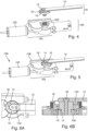
- Fig. 3 shows an exploded view of a drive 100 for a door, window, or the like with a second embodiment of the linkage 10 according to the invention.
- the linkage 10 in the second embodiment is constructed in the same way as in the first embodiment, but includes an actuator 18 as an additional component.
- the actuator 18 is designed as an electric lifting magnet, which is ring-shaped and configured to be arranged in a ring around the lock 16.
- the actuator 18 is configured to displace the lock 16 along the longitudinal axis 40 between the first position and the second position via an electromagnetic force.
- the drive 100 comprises a motor 102 and a drive unit 104 driven by the motor, which has an output shaft 106.
- the linkage 10 is configured to be connected to the output shaft 106 via the driver 14.
- the linkage 10 and in particular the driver 14 are configured to be attached to the drive 100 via a fastening element (not shown).
- the linkage 10 can easily replace an existing linkage and thus create a drive 100 that is capable of ensuring accessibility even in the event of a fire.
- Fig. 4 shows the drive 100 from Fig. 3 , wherein the rod 10 is shown in assembled state.
- Fig. 5 shows the drive 100 Fig. 4 with installed linkage 10 in perspective view.
- the actuator 18 is attached to the housing 108.
- Fig. 6A shows a section of the design of the drive 100 from Fig. 5 , wherein the lock is in the first position, in a view from above. It is clearly visible how the bolt 122 is clamped in the first position of the lock 16 between the driver 14 and the lock 16. A movement of the bolt 122 in the circumferential direction around the longitudinal axis (not shown) in the closing direction of the door is prevented in this position by the lock 16. In other words, the lock is in the first position active and the bolt is not free-running. In the first position, therefore, automatic operation of the drive 100 for a door (or window, etc.) is possible.
- Fig. 6B shows a section of the design of the drive 100 from Fig. 5 , with the lock in the first position, in a side sectional view.
- the driver 14 engages with the output shaft 106 or is connected thereto.
- the driver 14 rests against the lock 16 in the longitudinal direction (along the longitudinal axis 40) or the lock 16 is in engagement with the driver 14.
- a fastening element 50 in this case a screw, firmly connects the rod 10 to the drive (in the longitudinal direction 40; see also Fig. 7 ).
- the driver 14 is now freely movable in the circumferential direction about the longitudinal axis and can rotate relative to the bolt 122, in particular in the opening direction of the leaf, so that the driver 14 can in principle lead the bolt 122 in the opening direction of the leaf, thus allowing the bolt 122 (and thus the leaf) to run freely in the opening direction of the leaf.
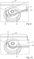
- the Figures 8 , 9 and 10 each show a section of the design of the drive 100 from Fig. 5 in perspective, with the drive 100 in emergency mode.
- Fig. 8 shows a section of the design of the drive 100 with the lock 16 in the second position.
- the driver 14 is rotated relative to the bolt 122 in the circumferential direction around the longitudinal axis in the opening direction of the wing (indicated by the arrow shown) and is in a so-called start position.
- the movement of the driver 14 can be transmitted via the output shaft 106 of the drive unit. 104 of the drive 100.
- the leaf In the state shown, the leaf is in the closed position.
- the rotation of the driver 14 about the longitudinal axis 40 occurs when the drive 100 is in emergency operation, i.e., in particular, when the control device outputs an emergency operation signal that also causes the actuator 18 to move the lock 16 into the second position.
- the linkage arm 12 moves in the opening direction (direction of the arrow). Consequently, the bolt 122 also moves in this direction and approaches the driver 14.
- the control device (not shown) of the drive 100 receives the information that the door has been opened. More precisely, the control device receives an opening signal and then causes a mechanical energy storage device, which is configured to be operatively connected to the driver 14 in emergency operation, to be discharged (virtually immediately or directly). The discharge of the energy storage device causes the driver to rotate opposite to the opening direction (i.e., opposite to the direction of the arrow) and thus move toward the bolt.
- Fig. 9 shows a further section of the design of the drive 100 from Fig. 5 in a perspective view, with the lock 16 in the second position.
- Fig. 9 It is shown how the bolt 122 moves towards the driver 14 during an opening movement of the wing (opposite the position in Fig. 8 ) has approached.
Landscapes
- Business, Economics & Management (AREA)
- Emergency Management (AREA)
- Power-Operated Mechanisms For Wings (AREA)
Applications Claiming Priority (1)
| Application Number | Priority Date | Filing Date | Title |
|---|---|---|---|
| DE102023134467.6A DE102023134467A1 (de) | 2023-12-08 | 2023-12-08 | Gestänge für barrierefreien Brandschutzantrieb |
Publications (1)
| Publication Number | Publication Date |
|---|---|
| EP4567236A1 true EP4567236A1 (fr) | 2025-06-11 |
Family
ID=93655849
Family Applications (1)
| Application Number | Title | Priority Date | Filing Date |
|---|---|---|---|
| EP24215441.7A Pending EP4567236A1 (fr) | 2023-12-08 | 2024-11-26 | Tringlerie pour entraînement de protection contre l'incendie sans barrière |
Country Status (2)
| Country | Link |
|---|---|
| EP (1) | EP4567236A1 (fr) |
| DE (1) | DE102023134467A1 (fr) |
Citations (4)
| Publication number | Priority date | Publication date | Assignee | Title |
|---|---|---|---|---|
| DE4426201A1 (de) | 1994-07-23 | 1996-01-25 | Geze Gmbh & Co | Antrieb für einen Drehflügel |
| EP0985794A2 (fr) * | 1998-09-07 | 2000-03-15 | GEZE GmbH | Commande pour l'ouvrant d'une porte , d'une fenêtre ou similaire |
| EP2735681A2 (fr) * | 2012-11-26 | 2014-05-28 | GEZE GmbH | Entraînement pour un battant de porte ou de fenêtre |
| DE102015000612A1 (de) | 2015-01-16 | 2016-07-21 | Assa Abloy Sicherheitstechnik Gmbh | Sicherungsvorrichtung zur Sicherung einer Tür in Flucht- und Rettungswagen |
-
2023
- 2023-12-08 DE DE102023134467.6A patent/DE102023134467A1/de active Pending
-
2024
- 2024-11-26 EP EP24215441.7A patent/EP4567236A1/fr active Pending
Patent Citations (5)
| Publication number | Priority date | Publication date | Assignee | Title |
|---|---|---|---|---|
| DE4426201A1 (de) | 1994-07-23 | 1996-01-25 | Geze Gmbh & Co | Antrieb für einen Drehflügel |
| EP0985794A2 (fr) * | 1998-09-07 | 2000-03-15 | GEZE GmbH | Commande pour l'ouvrant d'une porte , d'une fenêtre ou similaire |
| EP2735681A2 (fr) * | 2012-11-26 | 2014-05-28 | GEZE GmbH | Entraînement pour un battant de porte ou de fenêtre |
| DE102015000612A1 (de) | 2015-01-16 | 2016-07-21 | Assa Abloy Sicherheitstechnik Gmbh | Sicherungsvorrichtung zur Sicherung einer Tür in Flucht- und Rettungswagen |
| EP3245371B1 (fr) * | 2015-01-16 | 2020-01-15 | Assa Abloy Sicherheitstechnik GmbH | Dispositif de sécurité pour sécuriser une porte dans les voies d'évacuation et de sauvetage |
Also Published As
| Publication number | Publication date |
|---|---|
| DE102023134467A1 (de) | 2025-06-12 |
Similar Documents
| Publication | Publication Date | Title |
|---|---|---|
| DE4445698C2 (de) | Drehkreuzanlage | |
| DE102014212863B4 (de) | Klappensteuerung | |
| EP1092829A2 (fr) | Dispositif d'entraínement pour une porte | |
| DE2611359A1 (de) | Treibstangenverschluss, insbesondere fuer zweifluegelige feuerschutztueren | |
| EP2208846B1 (fr) | Dispositif pour la commande de la chaîne de fermeture de portes pivotantes à deux battants | |
| DE102008063061A1 (de) | Betätigungsvorrichtung für ein elektronisches Türschloß | |
| EP4386158B1 (fr) | Ouvre-porte | |
| EP3219886A1 (fr) | Barre de poussée comprenant un dispositif d'entraînement | |
| EP0715049A1 (fr) | Construction de porte tournante | |
| DE102010063477B4 (de) | Fernentriegelbare Torverriegelung | |
| EP3258045B1 (fr) | Entrainement de porte | |
| EP1544383B1 (fr) | Dispositif de sécurité contre les fausses manoeuvres pour une fenêtre, une porte ou similaire | |
| DE4430736C1 (de) | Impulsgesteuertes Fallenschloß | |
| DE60224483T2 (de) | Schwenktüre für Kraftfahrzeuge | |
| DE102009004503B4 (de) | Verfahren zum Betrieb eines Drehflügelbetätigers und damit betriebene Drehflügelbetätiger | |
| EP4567236A1 (fr) | Tringlerie pour entraînement de protection contre l'incendie sans barrière | |
| DE4242877C2 (de) | Verschließeinrichtung für Türflügel von Gebäudetüren | |
| EP2921617B1 (fr) | Dispositif de verrouillage | |
| EP2206867B1 (fr) | Actionneur de porte destiné à l'actionnement d'un vantail | |
| EP0335860B1 (fr) | Dispositif de secours pour une porte de véhicule à entraînement électrique sans blocage automatique | |
| DE102022209690B4 (de) | Türschließer mit Freilauffunktion | |
| DE102023134468B3 (de) | Antrieb mit Freilauffunktion für eine barrierefreie Begehung im Notfall | |
| DE19723174C2 (de) | Elektrisch betriebener Sicherheitsverschluß mit zusätzlichem Betätigungsantrieb für Türen und Fenster | |
| DE102004048467B4 (de) | Betätigungsvorrichtung für ein Türschloss | |
| EP3334877B1 (fr) | Dispositif de verrouillage de vantail coulissant |
Legal Events
| Date | Code | Title | Description |
|---|---|---|---|
| PUAI | Public reference made under article 153(3) epc to a published international application that has entered the european phase |
Free format text: ORIGINAL CODE: 0009012 |
|
| STAA | Information on the status of an ep patent application or granted ep patent |
Free format text: STATUS: THE APPLICATION HAS BEEN PUBLISHED |
|
| AK | Designated contracting states |
Kind code of ref document: A1 Designated state(s): AL AT BE BG CH CY CZ DE DK EE ES FI FR GB GR HR HU IE IS IT LI LT LU LV MC ME MK MT NL NO PL PT RO RS SE SI SK SM TR |
|
| P01 | Opt-out of the competence of the unified patent court (upc) registered |
Free format text: CASE NUMBER: APP_28082/2025 Effective date: 20250612 |
|
| STAA | Information on the status of an ep patent application or granted ep patent |
Free format text: STATUS: REQUEST FOR EXAMINATION WAS MADE |
|
| 17P | Request for examination filed |
Effective date: 20251209 |