EP4567291A1 - Drehführungslager mit mindestens einer rollenkäfiganordnung - Google Patents
Drehführungslager mit mindestens einer rollenkäfiganordnung Download PDFInfo
- Publication number
- EP4567291A1 EP4567291A1 EP24215844.2A EP24215844A EP4567291A1 EP 4567291 A1 EP4567291 A1 EP 4567291A1 EP 24215844 A EP24215844 A EP 24215844A EP 4567291 A1 EP4567291 A1 EP 4567291A1
- Authority
- EP
- European Patent Office
- Prior art keywords
- bearing
- ring
- roller
- rotation
- cage
- Prior art date
- Legal status (The legal status is an assumption and is not a legal conclusion. Google has not performed a legal analysis and makes no representation as to the accuracy of the status listed.)
- Pending
Links
Images

Classifications
-
- F—MECHANICAL ENGINEERING; LIGHTING; HEATING; WEAPONS; BLASTING
- F16—ENGINEERING ELEMENTS AND UNITS; GENERAL MEASURES FOR PRODUCING AND MAINTAINING EFFECTIVE FUNCTIONING OF MACHINES OR INSTALLATIONS; THERMAL INSULATION IN GENERAL
- F16C—SHAFTS; FLEXIBLE SHAFTS; ELEMENTS OR CRANKSHAFT MECHANISMS; ROTARY BODIES OTHER THAN GEARING ELEMENTS; BEARINGS
- F16C19/00—Bearings with rolling contact, for exclusively rotary movement
- F16C19/22—Bearings with rolling contact, for exclusively rotary movement with bearing rollers essentially of the same size in one or more circular rows, e.g. needle bearings
- F16C19/34—Bearings with rolling contact, for exclusively rotary movement with bearing rollers essentially of the same size in one or more circular rows, e.g. needle bearings for both radial and axial load
- F16C19/38—Bearings with rolling contact, for exclusively rotary movement with bearing rollers essentially of the same size in one or more circular rows, e.g. needle bearings for both radial and axial load with two or more rows of rollers
- F16C19/383—Bearings with rolling contact, for exclusively rotary movement with bearing rollers essentially of the same size in one or more circular rows, e.g. needle bearings for both radial and axial load with two or more rows of rollers with tapered rollers, i.e. rollers having essentially the shape of a truncated cone
-
- F—MECHANICAL ENGINEERING; LIGHTING; HEATING; WEAPONS; BLASTING
- F16—ENGINEERING ELEMENTS AND UNITS; GENERAL MEASURES FOR PRODUCING AND MAINTAINING EFFECTIVE FUNCTIONING OF MACHINES OR INSTALLATIONS; THERMAL INSULATION IN GENERAL
- F16C—SHAFTS; FLEXIBLE SHAFTS; ELEMENTS OR CRANKSHAFT MECHANISMS; ROTARY BODIES OTHER THAN GEARING ELEMENTS; BEARINGS
- F16C19/00—Bearings with rolling contact, for exclusively rotary movement
- F16C19/22—Bearings with rolling contact, for exclusively rotary movement with bearing rollers essentially of the same size in one or more circular rows, e.g. needle bearings
- F16C19/34—Bearings with rolling contact, for exclusively rotary movement with bearing rollers essentially of the same size in one or more circular rows, e.g. needle bearings for both radial and axial load
- F16C19/38—Bearings with rolling contact, for exclusively rotary movement with bearing rollers essentially of the same size in one or more circular rows, e.g. needle bearings for both radial and axial load with two or more rows of rollers
- F16C19/381—Bearings with rolling contact, for exclusively rotary movement with bearing rollers essentially of the same size in one or more circular rows, e.g. needle bearings for both radial and axial load with two or more rows of rollers with at least one row for radial load in combination with at least one row for axial load
-
- F—MECHANICAL ENGINEERING; LIGHTING; HEATING; WEAPONS; BLASTING
- F16—ENGINEERING ELEMENTS AND UNITS; GENERAL MEASURES FOR PRODUCING AND MAINTAINING EFFECTIVE FUNCTIONING OF MACHINES OR INSTALLATIONS; THERMAL INSULATION IN GENERAL
- F16C—SHAFTS; FLEXIBLE SHAFTS; ELEMENTS OR CRANKSHAFT MECHANISMS; ROTARY BODIES OTHER THAN GEARING ELEMENTS; BEARINGS
- F16C19/00—Bearings with rolling contact, for exclusively rotary movement
- F16C19/54—Systems consisting of a plurality of bearings with rolling friction
- F16C19/545—Systems comprising at least one rolling bearing for radial load in combination with at least one rolling bearing for axial load
-
- F—MECHANICAL ENGINEERING; LIGHTING; HEATING; WEAPONS; BLASTING
- F16—ENGINEERING ELEMENTS AND UNITS; GENERAL MEASURES FOR PRODUCING AND MAINTAINING EFFECTIVE FUNCTIONING OF MACHINES OR INSTALLATIONS; THERMAL INSULATION IN GENERAL
- F16C—SHAFTS; FLEXIBLE SHAFTS; ELEMENTS OR CRANKSHAFT MECHANISMS; ROTARY BODIES OTHER THAN GEARING ELEMENTS; BEARINGS
- F16C33/00—Parts of bearings; Special methods for making bearings or parts thereof
- F16C33/30—Parts of ball or roller bearings
- F16C33/34—Rollers; Needles
-
- F—MECHANICAL ENGINEERING; LIGHTING; HEATING; WEAPONS; BLASTING
- F16—ENGINEERING ELEMENTS AND UNITS; GENERAL MEASURES FOR PRODUCING AND MAINTAINING EFFECTIVE FUNCTIONING OF MACHINES OR INSTALLATIONS; THERMAL INSULATION IN GENERAL
- F16C—SHAFTS; FLEXIBLE SHAFTS; ELEMENTS OR CRANKSHAFT MECHANISMS; ROTARY BODIES OTHER THAN GEARING ELEMENTS; BEARINGS
- F16C33/00—Parts of bearings; Special methods for making bearings or parts thereof
- F16C33/30—Parts of ball or roller bearings
- F16C33/46—Cages for rollers or needles
- F16C33/54—Cages for rollers or needles made from wire, strips, or sheet metal
- F16C33/542—Cages for rollers or needles made from wire, strips, or sheet metal made from sheet metal
- F16C33/543—Cages for rollers or needles made from wire, strips, or sheet metal made from sheet metal from a single part
-
- F—MECHANICAL ENGINEERING; LIGHTING; HEATING; WEAPONS; BLASTING
- F16—ENGINEERING ELEMENTS AND UNITS; GENERAL MEASURES FOR PRODUCING AND MAINTAINING EFFECTIVE FUNCTIONING OF MACHINES OR INSTALLATIONS; THERMAL INSULATION IN GENERAL
- F16C—SHAFTS; FLEXIBLE SHAFTS; ELEMENTS OR CRANKSHAFT MECHANISMS; ROTARY BODIES OTHER THAN GEARING ELEMENTS; BEARINGS
- F16C33/00—Parts of bearings; Special methods for making bearings or parts thereof
- F16C33/30—Parts of ball or roller bearings
- F16C33/46—Cages for rollers or needles
- F16C33/54—Cages for rollers or needles made from wire, strips, or sheet metal
- F16C33/542—Cages for rollers or needles made from wire, strips, or sheet metal made from sheet metal
- F16C33/547—Cages for rollers or needles made from wire, strips, or sheet metal made from sheet metal from two parts, e.g. two discs or rings joined together
-
- F—MECHANICAL ENGINEERING; LIGHTING; HEATING; WEAPONS; BLASTING
- F16—ENGINEERING ELEMENTS AND UNITS; GENERAL MEASURES FOR PRODUCING AND MAINTAINING EFFECTIVE FUNCTIONING OF MACHINES OR INSTALLATIONS; THERMAL INSULATION IN GENERAL
- F16C—SHAFTS; FLEXIBLE SHAFTS; ELEMENTS OR CRANKSHAFT MECHANISMS; ROTARY BODIES OTHER THAN GEARING ELEMENTS; BEARINGS
- F16C2220/00—Shaping
- F16C2220/80—Shaping by separating parts, e.g. by severing, cracking
- F16C2220/84—Shaping by separating parts, e.g. by severing, cracking by perforating; by punching; by stamping-out
-
- F—MECHANICAL ENGINEERING; LIGHTING; HEATING; WEAPONS; BLASTING
- F16—ENGINEERING ELEMENTS AND UNITS; GENERAL MEASURES FOR PRODUCING AND MAINTAINING EFFECTIVE FUNCTIONING OF MACHINES OR INSTALLATIONS; THERMAL INSULATION IN GENERAL
- F16C—SHAFTS; FLEXIBLE SHAFTS; ELEMENTS OR CRANKSHAFT MECHANISMS; ROTARY BODIES OTHER THAN GEARING ELEMENTS; BEARINGS
- F16C2360/00—Engines or pumps
- F16C2360/31—Wind motors
Definitions
- the invention relates to a roller cage assembly for guiding in rotation, about a main axis of rotation, a first bearing ring relative to a second bearing ring.
- the invention also relates to a rotation guide bearing capable of being interposed between two elements of a structure which are mounted to rotate relative to each other.
- one or more cages may be integrated into a rotating guide bearing, or rolling bearing.
- Roller guidance is very important to avoid contact between the rollers, which would cause their wear and premature failure, and to keep the rotation axis of each of the rollers in the optimal position, to avoid an increase in torque and premature failure.
- a first problem with this standard guidance is that the number of rollers is limited by the thickness of the cage wall between adjacent rollers.
- cages or segments of cages, may be used in which the cage has a series of windows in each of which a roller is arranged with play.
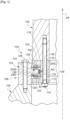
- the two components 102 and 104 are for example the lower end of a wind turbine blade pivotally assembled on a rotor hub 104.
- the assembly of the three components 102, 110 and 112 is carried out by means of a set of axial bolts 114 distributed circumferentially around the main axis AP.
- the first bearing ring 108 comprises a housing 116 which is open radially, here outwards, relative to the main axis of rotation.
- the housing 116 of the bearing ring 108 is formed partly in the lower part 112 and partly in the upper part 110 and it is delimited vertically by two planar and opposite annular faces orthogonal to the main axis AP, including an upper face 122 and a lower face 123.
- Each flat annular face 122, 123 constitutes a flat annular rolling track belonging to the first rolling ring 108.
- the face 118 constitutes a cylindrical rolling track belonging to the first rolling ring 108.
- the bearing 106 comprises a second bearing ring 124 - radially external with respect to the main axis AP - in a single part on which the component 104 is fixed.
- the assembly of the two components 104 and 124 is carried out by means of a set of axial bolts 126 distributed circumferentially around the main axis AP.
- the second bearing ring 124 comprises a projecting portion 128 which here extends radially towards the main axis AP inside the housing 116 of the first bearing ring 108.
- the projecting part, or nose, 128 is delimited vertically by two flat and opposite annular faces orthogonal to the main axis AP, including an upper face 132 and a lower face 133.
- Each flat annular face 132, 133 constitutes a flat annular rolling track belonging to the second rolling ring 124.
- the projecting portion 128 is also delimited, radially inwards, by a concave cylindrical face of axial orientation 130.
- the face 130 constitutes a cylindrical rolling track belonging to the second rolling ring 124.
- the protruding portion 128 extends radially inwardly from a concave axial cylindrical surface 129 of the body of the second bearing ring 124.
- the rotation axes AS and AI of the rollers of the two roller cage assemblies 200S and 200I are orthogonal to the main rotation axis AP.
- the two roller cage assemblies 200S and 200I of the bearing 106 are capable of supporting axial loads oriented parallel to the main axis AP.
- the design of the two roller cage assemblies 200S and 200I of the bearing 106 is identical here.
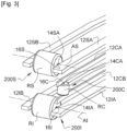
- a central roller cage assembly 200C is interposed radially between the cylindrical and parallel rolling races 118 and 130.
- the rotation axes of the rollers of the central roller cage assembly 200C are parallel to the main rotation axis AP.
- the 200C central roller cage assembly is capable of supporting radial loads oriented orthogonally to the main axis AP.
- each series of rollers belonging to a 200S, 200I or 200C roller cage is arranged in a circle angularly around the main axis AP.
- the 200C assembly comprises a series of RC rollers each having an individual axis of rotation AC and which are distributed circumferentially around the main axis AP.
- the 200C assembly here comprises a 10C cage, for guiding and circumferentially positioning the RC rollers, in two complementary parts 10CA and 10CB (See Figure 4 ) each of which has a 12CA, 12CB ring.
- Each ring 12CA, 12CB has a series of fingers 14CA, 14CB which are distributed circumferentially along the ring 12CA, 12CB.
- Each ring, or ring sector, 12CA, 12CB is made in a single piece with its associated series of fingers.
- each ring 12CA, 12CB is in the form of a sheet or plate which is here curved to adopt a generally cylindrical conformation.
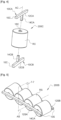
- each RC roller has an axial through hole 16C which opens at the two opposite axial ends of the RC roller.
- Each finger 14CA, 14CB is received inside an axial hole 16C of an associated RC roller.
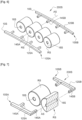
- each of the two upper roller cage assemblies 200S and 200I is identical here.
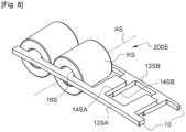
- the 200S assembly comprises a series of rollers RS each having an individual axis of rotation AS which are distributed circumferentially around the main axis AP.
- the 200S assembly here comprises a 10S cage for guiding and circumferentially positioning the RS rollers, in two complementary parts 10SA and 10SB, each of which comprises a 12SA, 12SB ring.
- Each 12SA, 12SB ring has a series of 14SA, 14SB fingers which are distributed circumferentially along the 12SA, 12SB ring.
- Each ring, or ring sector, 12SA is made in one piece with its associated series of fingers.
- each ring 12SA, 12SB is in the form of a flat annular sheet or plate.
- each RS roller has a through axial hole 16S which opens at the two opposite axial ends of the RS roller.
- each finger 14SA, 14SB is received inside an axial hole 16S of an associated roller RS.
- the corresponding components of the assembly 200l are designated by the same alphanumeric references indexed “I”, namely RI, Al, 10I, 12IA, 12IB, 14IA, 14IB, 16I.
- each ring 12CA, 12CB, 12SA, 12SB, 12IA, 12IB with its fingers 14CA, 14CB, 14SA, 14SB, 14IA, 14IB is produced by cutting, in particular by laser cutting, in a metal sheet.
- a polyamide (PA) coating can be applied similar to that used for coating ball bearing cages; for example, a polyamide PA11 or PA12 which can be deposited by immersion in a fluidized bath.
- Such a production method is notably more economical than the production of molded plastic cages, which requires the manufacture of as many molds as necessary.
- the fingers may be of circular section requiring the implementation of other manufacturing techniques, or additional manufacturing steps.
- each roller RC, RS, RI is a cylindrical roller of substantially constant section and comprises an axial through hole 16C, 16S, 16I (each axial end of which is capable of receiving a finger 14CA, 14CB, 14SA, 14SB, 14IA, 14IB)
- each cylindrical roller can be produced by cutting a section of tube.
- the maximum hole diameter is defined based on the minimum load capacity of the roller.
- the fingers 14SA of the radially inner ring 10SA are introduced through the four axial holes 16S of the rollers RS, then the fingers 14SB of the radially outer ring 12SB are introduced into the axial holes 16S of the rollers RS.
- the “pre-assembled” 200S assembly can be placed in position inside the bearing 106 between the bearing rings 108 and 124.
- the two complementary rings 12SA and 12SB can be joined to each other.
- the free end sections of two aligned and opposite fingers 14SA and 14SB received inside the same roller RS overlap axially and are fixed to each other.
- each roller cage assembly can be produced in the form of a complete annular assembly extending over 360°, or in the form of a roller cage segment extending over an arc of a circle, several segments being able to be associated along a circumference.
- a roller cage assembly may consist of only a single ring or a single ring segment with its fingers which are received in the associated series of rollers.
- the number of rollers equipping a cage can be determined in particular according to the loads to be absorbed.
- each cylindrical roller may have a profile approaching that of a cylinder with a rectilinear generator (as illustrated in the figures) and in particular have a barrel-shaped or curved profile.
- the invention also finds application to assemblies comprising conical or truncated conical rollers.
- Each roller can also be made from a section of solid bar.
- the end hole(s) can be made by drilling.
- rollers of a series may roll on the surface of an associated track or be received in a groove cut into that surface.
- Each bearing ring can be made in one or more parts.
- the invention also finds application to a bearing comprising, for example, only two opposing assemblies similar to the assemblies 200S and 200I described previously which are received between opposing annular frustoconical rolling tracks each forming an angle relative to the main axis of rotation.
- the invention is applicable to the design of all types of rolling or bearing, including for a linear displacement guide capable of being interposed between two elements of a structure which are mounted to move relative to each other, this bearing comprising a first rolling element, made in one or more parts, a second rolling element, made in one or more parts, extending parallel to the first rolling element, and at least one assembly for guiding the first rolling element relative to the second rolling element made according to the principle of the invention and in which and a cage for guiding and circumferentially positioning the rollers around said main axis, in which the cage comprises at least one rectilinear segment which comprises a series of fingers distributed linearly, each of which is received inside an axial hole of a roller, each rectilinear segment and the series of fingers being made in a single piece.
Landscapes
- Engineering & Computer Science (AREA)
- General Engineering & Computer Science (AREA)
- Mechanical Engineering (AREA)
- Rolling Contact Bearings (AREA)
Applications Claiming Priority (1)
| Application Number | Priority Date | Filing Date | Title |
|---|---|---|---|
| FR2313727A FR3156493B1 (fr) | 2023-12-07 | 2023-12-07 | Ensemble de cage a rouleaux et palier de guidage en rotation comportant au moins un tel ensemble |
Publications (1)
| Publication Number | Publication Date |
|---|---|
| EP4567291A1 true EP4567291A1 (de) | 2025-06-11 |
Family
ID=90458159
Family Applications (1)
| Application Number | Title | Priority Date | Filing Date |
|---|---|---|---|
| EP24215844.2A Pending EP4567291A1 (de) | 2023-12-07 | 2024-11-27 | Drehführungslager mit mindestens einer rollenkäfiganordnung |
Country Status (2)
| Country | Link |
|---|---|
| EP (1) | EP4567291A1 (de) |
| FR (1) | FR3156493B1 (de) |
Citations (9)
| Publication number | Priority date | Publication date | Assignee | Title |
|---|---|---|---|---|
| US471711A (en) * | 1892-03-29 | Wheel | ||
| FR2072552A5 (de) | 1969-11-28 | 1971-09-24 | Hoesch Ag | |
| JPS63312512A (ja) * | 1987-06-15 | 1988-12-21 | Koyo Seiko Co Ltd | 複合円筒ころ軸受 |
| US5256495A (en) | 1991-08-05 | 1993-10-26 | The Torrington Company | Pin type bearing retainer |
| JP2002372053A (ja) | 2001-06-12 | 2002-12-26 | Tsubakimoto Chain Co | ころ軸受及びころ軸受を組み込んだチェーン |
| JP2007205557A (ja) | 2006-02-06 | 2007-08-16 | Ntn Corp | 転がり軸受、保持器セグメントおよび風力発電機の主軸支持構造 |
| EP2172664A1 (de) | 2007-06-29 | 2010-04-07 | JTEKT Corporation | Stiftartiger halter, verfahren zur anbringung von kugeln an dem stiftartigen halter und kugellager |
| EP2503164B1 (de) | 2011-03-25 | 2016-06-15 | Defontaine | Lager mit drei Reihen und mehr von Wälzkörpern |
| DE102018117839A1 (de) | 2018-07-24 | 2020-01-30 | Schaeffler Technologies AG & Co. KG | Pendelrollenlager und Verfahren zur Herstellung eines Pendelrollenlagers |
-
2023
- 2023-12-07 FR FR2313727A patent/FR3156493B1/fr active Active
-
2024
- 2024-11-27 EP EP24215844.2A patent/EP4567291A1/de active Pending
Patent Citations (10)
| Publication number | Priority date | Publication date | Assignee | Title |
|---|---|---|---|---|
| US471711A (en) * | 1892-03-29 | Wheel | ||
| FR2072552A5 (de) | 1969-11-28 | 1971-09-24 | Hoesch Ag | |
| US3652141A (en) | 1969-11-28 | 1972-03-28 | Hoesch Ag | Combined three-sectional axial-radial roller turning connection |
| JPS63312512A (ja) * | 1987-06-15 | 1988-12-21 | Koyo Seiko Co Ltd | 複合円筒ころ軸受 |
| US5256495A (en) | 1991-08-05 | 1993-10-26 | The Torrington Company | Pin type bearing retainer |
| JP2002372053A (ja) | 2001-06-12 | 2002-12-26 | Tsubakimoto Chain Co | ころ軸受及びころ軸受を組み込んだチェーン |
| JP2007205557A (ja) | 2006-02-06 | 2007-08-16 | Ntn Corp | 転がり軸受、保持器セグメントおよび風力発電機の主軸支持構造 |
| EP2172664A1 (de) | 2007-06-29 | 2010-04-07 | JTEKT Corporation | Stiftartiger halter, verfahren zur anbringung von kugeln an dem stiftartigen halter und kugellager |
| EP2503164B1 (de) | 2011-03-25 | 2016-06-15 | Defontaine | Lager mit drei Reihen und mehr von Wälzkörpern |
| DE102018117839A1 (de) | 2018-07-24 | 2020-01-30 | Schaeffler Technologies AG & Co. KG | Pendelrollenlager und Verfahren zur Herstellung eines Pendelrollenlagers |
Also Published As
| Publication number | Publication date |
|---|---|
| FR3156493A1 (fr) | 2025-06-13 |
| FR3156493B1 (fr) | 2025-12-26 |
Similar Documents
| Publication | Publication Date | Title |
|---|---|---|
| EP2021641B1 (de) | Kugellagerkäfig | |
| FR2923277A1 (fr) | Palier a roulement a lubrification interne | |
| FR2945090A1 (fr) | Palier a roulement comportant une enveloppe de maintien d'une des bagues | |
| EP1956254B1 (de) | Rollvorrichtung und Lenksäule | |
| FR3018322A1 (fr) | Organe de liaison rotule a lubrification permanente | |
| FR2936767A1 (fr) | Palier a roulement, notamment pour colonne de direction. | |
| FR3007807A1 (fr) | Palier a roulement, notamment pour colonne de direction, et procede de fabrication associe | |
| FR3040750A1 (fr) | Dispositif d'etancheite pour unite de palier a roulement | |
| FR2948158A1 (fr) | Palier pour une bielle | |
| EP4567291A1 (de) | Drehführungslager mit mindestens einer rollenkäfiganordnung | |
| FR2755734A1 (fr) | Roulement a charge radiale avec une cage retenue par des rebords de la bague exterieure | |
| FR2869081A1 (fr) | Palier a roulement | |
| FR2925943A1 (fr) | Assemblage pour roulement a rouleaux coniques et son procede de fabrication | |
| EP3565983B1 (de) | Synchronisierte freilaufrolle | |
| EP2878841B1 (de) | Rückhaltekäfig von Rollkörpern in einem Wälzlager | |
| EP2963307B1 (de) | Rückhaltekäfig von rollkörpern in einem wälzlager | |
| EP3997353B1 (de) | Schmiermittelrückführung in einem wälzlager für eine turbomaschine | |
| FR3034151A1 (fr) | Palier comprenant une bague d'usure surmoulee, et procede de fabrication associe | |
| FR3097283A1 (fr) | Palier de joint universel scellé et ensemble de palier de joint universel | |
| FR3104655A1 (fr) | Roulement à trois points de contact avec drain amélioré | |
| EP2811189A1 (de) | Segmentiertes Gehäuse für Rolleinheit | |
| FR3001014A1 (fr) | Bague exterieure fixe de roulement avec au moins un orifice de drainage traversant un rebord de guidage d'au moins un element roulant | |
| FR2897126A1 (fr) | Dispositif de roulement et colonne de direction. | |
| FR3105809A1 (fr) | Cage de roulement à retenue latérale | |
| FR2886693A1 (fr) | Dispositif anti-rotation pour bague de roulement, et roulement et machine associes |
Legal Events
| Date | Code | Title | Description |
|---|---|---|---|
| PUAI | Public reference made under article 153(3) epc to a published international application that has entered the european phase |
Free format text: ORIGINAL CODE: 0009012 |
|
| STAA | Information on the status of an ep patent application or granted ep patent |
Free format text: STATUS: THE APPLICATION HAS BEEN PUBLISHED |
|
| AK | Designated contracting states |
Kind code of ref document: A1 Designated state(s): AL AT BE BG CH CY CZ DE DK EE ES FI FR GB GR HR HU IE IS IT LI LT LU LV MC ME MK MT NL NO PL PT RO RS SE SI SK SM TR |
|
| STAA | Information on the status of an ep patent application or granted ep patent |
Free format text: STATUS: REQUEST FOR EXAMINATION WAS MADE |
|
| 17P | Request for examination filed |
Effective date: 20251211 |