EP4567331A1 - Buse de chambre de combustion, chambre de combustion et turbine à gaz comprenant celle-ci - Google Patents
Buse de chambre de combustion, chambre de combustion et turbine à gaz comprenant celle-ci Download PDFInfo
- Publication number
- EP4567331A1 EP4567331A1 EP24211033.6A EP24211033A EP4567331A1 EP 4567331 A1 EP4567331 A1 EP 4567331A1 EP 24211033 A EP24211033 A EP 24211033A EP 4567331 A1 EP4567331 A1 EP 4567331A1
- Authority
- EP
- European Patent Office
- Prior art keywords
- fuel
- tube
- mixing tube
- supply member
- fuel supply
- Prior art date
- Legal status (The legal status is an assumption and is not a legal conclusion. Google has not performed a legal analysis and makes no representation as to the accuracy of the status listed.)
- Pending
Links
Images


Classifications
-
- F—MECHANICAL ENGINEERING; LIGHTING; HEATING; WEAPONS; BLASTING
- F23—COMBUSTION APPARATUS; COMBUSTION PROCESSES
- F23R—GENERATING COMBUSTION PRODUCTS OF HIGH PRESSURE OR HIGH VELOCITY, e.g. GAS-TURBINE COMBUSTION CHAMBERS
- F23R3/00—Continuous combustion chambers using liquid or gaseous fuel
- F23R3/28—Continuous combustion chambers using liquid or gaseous fuel characterised by the fuel supply
- F23R3/286—Continuous combustion chambers using liquid or gaseous fuel characterised by the fuel supply having fuel-air premixing devices
-
- F—MECHANICAL ENGINEERING; LIGHTING; HEATING; WEAPONS; BLASTING
- F02—COMBUSTION ENGINES; HOT-GAS OR COMBUSTION-PRODUCT ENGINE PLANTS
- F02C—GAS-TURBINE PLANTS; AIR INTAKES FOR JET-PROPULSION PLANTS; CONTROLLING FUEL SUPPLY IN AIR-BREATHING JET-PROPULSION PLANTS
- F02C3/00—Gas-turbine plants characterised by the use of combustion products as the working fluid
- F02C3/20—Gas-turbine plants characterised by the use of combustion products as the working fluid using a special fuel, oxidant, or dilution fluid to generate the combustion products
-
- F—MECHANICAL ENGINEERING; LIGHTING; HEATING; WEAPONS; BLASTING
- F02—COMBUSTION ENGINES; HOT-GAS OR COMBUSTION-PRODUCT ENGINE PLANTS
- F02C—GAS-TURBINE PLANTS; AIR INTAKES FOR JET-PROPULSION PLANTS; CONTROLLING FUEL SUPPLY IN AIR-BREATHING JET-PROPULSION PLANTS
- F02C7/00—Features, components parts, details or accessories, not provided for in, or of interest apart form groups F02C1/00 - F02C6/00; Air intakes for jet-propulsion plants
- F02C7/22—Fuel supply systems
-
- F—MECHANICAL ENGINEERING; LIGHTING; HEATING; WEAPONS; BLASTING
- F23—COMBUSTION APPARATUS; COMBUSTION PROCESSES
- F23C—METHODS OR APPARATUS FOR COMBUSTION USING FLUID FUEL OR SOLID FUEL SUSPENDED IN A CARRIER GAS OR AIR
- F23C1/00—Combustion apparatus specially adapted for combustion of two or more kinds of fuel simultaneously or alternately, at least one kind of fuel being either a fluid fuel or a solid fuel suspended in a carrier gas or air
-
- F—MECHANICAL ENGINEERING; LIGHTING; HEATING; WEAPONS; BLASTING
- F23—COMBUSTION APPARATUS; COMBUSTION PROCESSES
- F23R—GENERATING COMBUSTION PRODUCTS OF HIGH PRESSURE OR HIGH VELOCITY, e.g. GAS-TURBINE COMBUSTION CHAMBERS
- F23R3/00—Continuous combustion chambers using liquid or gaseous fuel
- F23R3/28—Continuous combustion chambers using liquid or gaseous fuel characterised by the fuel supply
- F23R3/36—Supply of different fuels
-
- F—MECHANICAL ENGINEERING; LIGHTING; HEATING; WEAPONS; BLASTING
- F05—INDEXING SCHEMES RELATING TO ENGINES OR PUMPS IN VARIOUS SUBCLASSES OF CLASSES F01-F04
- F05D—INDEXING SCHEME FOR ASPECTS RELATING TO NON-POSITIVE-DISPLACEMENT MACHINES OR ENGINES, GAS-TURBINES OR JET-PROPULSION PLANTS
- F05D2220/00—Application
- F05D2220/30—Application in turbines
- F05D2220/32—Application in turbines in gas turbines
-
- F—MECHANICAL ENGINEERING; LIGHTING; HEATING; WEAPONS; BLASTING
- F05—INDEXING SCHEMES RELATING TO ENGINES OR PUMPS IN VARIOUS SUBCLASSES OF CLASSES F01-F04
- F05D—INDEXING SCHEME FOR ASPECTS RELATING TO NON-POSITIVE-DISPLACEMENT MACHINES OR ENGINES, GAS-TURBINES OR JET-PROPULSION PLANTS
- F05D2240/00—Components
- F05D2240/35—Combustors or associated equipment
-
- F—MECHANICAL ENGINEERING; LIGHTING; HEATING; WEAPONS; BLASTING
- F23—COMBUSTION APPARATUS; COMBUSTION PROCESSES
- F23C—METHODS OR APPARATUS FOR COMBUSTION USING FLUID FUEL OR SOLID FUEL SUSPENDED IN A CARRIER GAS OR AIR
- F23C2900/00—Special features of, or arrangements for combustion apparatus using fluid fuels or solid fuels suspended in air; Combustion processes therefor
- F23C2900/9901—Combustion process using hydrogen, hydrogen peroxide water or brown gas as fuel
-
- F—MECHANICAL ENGINEERING; LIGHTING; HEATING; WEAPONS; BLASTING
- F23—COMBUSTION APPARATUS; COMBUSTION PROCESSES
- F23R—GENERATING COMBUSTION PRODUCTS OF HIGH PRESSURE OR HIGH VELOCITY, e.g. GAS-TURBINE COMBUSTION CHAMBERS
- F23R2900/00—Special features of, or arrangements for continuous combustion chambers; Combustion processes therefor
- F23R2900/00002—Gas turbine combustors adapted for fuels having low heating value [LHV]
Definitions
- the present invention relates to a combustor nozzle, a combustor, and a gas turbine and, more particularly, to a combustor nozzle using hydrogen-containing fuel, a combustor, and a gas turbine including the same.
- a gas turbine is a combustion engine in which a mixture of air compressed by a compressor and fuel is combusted to produce a high temperature gas, which drives a turbine.
- the gas turbine may be used to drive electric generators, aircraft, ships, trains, or the like.
- a gas turbine generally includes a compressor, a combustor, and a turbine.
- the compressor serves to intake external air, compress the air, and transfer the compressed air to the combustor.
- the compressed air compressed by the compressor has a high temperature and a high pressure.
- the combustor serves to mix compressed air from the compressor and fuel and combust the mixture of compressed air and fuel to produce combustion gases, which are discharged to the gas turbine.
- the combustion gases drive turbine blades in the turbine to produce power.
- the power generated through the above processes may be applied to a variety of fields such as generation of electricity, driving of mechanical units, etc.
- Fuel is injected through nozzles disposed in respective combustors, wherein the fuel includes gaseous fuel and liquid fuel.
- the fuel includes gaseous fuel and liquid fuel.
- KR 2020-0027894 A propose a combustor nozzle having multiple tubes.
- the nozzle with multiple tubes is efficient for combustion of hydrogen by discharging fuel at a high speed, but when hydrocarbon-based fuel such as natural gas is supplied to the multiple tubes, the fuel is injected at an excessively high speed, causing the flame to escape from the nozzle.
- the combustor with multiple tubes has the problem of not being able to burn a wide variety of fuels.
- an objective of the present invention is to provide a combustor nozzle capable of burning a variety of fuels other than hydrogen-based fuels, a combustor, and a gas turbine including the same.
- the present invention provides a combustor nozzle in accordance with claim 1, a combustor in accordance with claim 13, and a gas turbine in accordance with claim 14.
- Advantageous embodiments are subject to the dependent claims and the following description, referring to the drawings.
- a first aspect of the present invention provides a combustor nozzle including: a plurality of mixing tubes through which air and fuel flow; an accommodation tube accommodating and supporting the plurality of mixing tubes therein; a first fuel tube coupled to the accommodation tube to supply a first fuel into the accommodation tube; a second fuel tube coupled to the accommodation tube to supply a second fuel into the accommodation tube; a dispersion chamber provided in the accommodation tube so as to be combined with the second fuel tube to receive the second fuel therein; a first fuel supply member supplying the first fuel received in the accommodation tube into each mixing tube; and a second fuel supply member supplying the second fuel received in the dispersion chamber into each mixing tube.
- the accommodation tube may define an interior space and extend in a longitudinal direction between a first or leading end, and a second or rear end.
- Each mixing tube may have an outlet for discharging the air and fuel flow.
- the mixing tubes may extend along the longitudinal direction within the interior space of the accommodation tube, and the outlet of the mixing tube may be disposed in the region of or at the first end of the accommodation tube.
- the mixing tubes optionally, may have a cross-section of a hollow cylinder.
- the dispersion chamber may be disposed in the interior space of the accommodation tube.
- the dispersion chamber may be a housing structure that limits an interior space or void.
- the first fuel tube may extend into the interior space defined by the accommodation tube and may be configured to discharge fuel directly into a first distribution space, which may be limited by the accommodation tube itself.
- the interior space or void limited by the dispersion chamber may be referred to as a second distribution space, and the second fuel tube may be connected to the second distribution space so as to be configured to discharge fuel into the second distribution space.
- Each first fuel supply member forms a fluid communication between the first distribution space and a respective mixing tube
- each second fuel supply member forms a fluid communication between the second distribution space and the respective mixing tube.
- the first fuel supply member connects the interior space of the accommodation tube outside the dispersion chamber, e.g., the first distribution space, to the respective mixing tube
- the second fuel supply member connects the dispersion chamber, e.g., the second distribution space, to the respective mixing tube.
- the nozzle may comprise a plurality of accommodation tubes, wherein each accommodation tube accommodates and supports a plurality of mixing tubes, a respective first fuel tube and a respective second fuel tube is coupled to each accommodation tube, and a respective dispersion chamber is provided in each accommodation tube.
- the second fuel supply member may be configured to form a concentrated fuel flow flowing along an inner circumferential wall of the mixing tube. Hence, in the concentrated fuel flow along the inner circumferential surface of the wall of the mixing tube, a higher concentration of fuel may be present than in the surrounding.
- Two or more second fuel supply members may be circumferentially provided on the mixing tube so as to be spaced apart from each other to form an annular concentrated fuel flow.
- An outlet of the first fuel supply member may be disposed closer to the center of the mixing tube than an outlet of the second fuel supply member.
- the center of the mixing tube may be on a central axis of the mixing tube.
- An inclination angle between the second fuel supply member and an inner circumferential wall surface of the mixing tube may be smaller than an inclination angle between the first fuel supply member and the inner circumferential wall surface of the mixing tube.
- an inclination angle of a longitudinal extension line of the second fuel supply member with the inner circumferential wall (surface) of the mixing tube may be formed to be smaller than that of a longitudinal extension line of the first fuel supply member with the inner circumferential wall (surface) of the mixing tube.
- the longitudinal extension line of the second fuel supply member may, for example, be parallel to a central axis defined by the outlet of the second fuel supply member.
- longitudinal extension line of the first fuel supply member may, for example, be parallel to a central axis defined by the outlet of the first fuel supply member.
- the first fuel may include a hydrogen-based fuel having hydrogen as a major component or a hydrocarbon-based fuel having hydrocarbon as a major component
- the second fuel may include a hydrocarbon-based fuel having hydrocarbon as a major component
- the second fuel supply member may include a hole formed in the mixing tube, the hole being inclined downstream with respect to the radial direction of the mixing tube.
- an outlet of the hole may be oriented towards the center of the mixing tube and towards the front end or outlet of the mixing tube.
- the second fuel supply member may include a tubular member.
- the tubular member may penetrate the circumferential wall of the mixing tube.
- the tubular member may extend into the mixing tube and protrude from the inner circumferential surface of the mixing tube, or may end flush with the inner circumferential surface of the mixing tube.
- the first fuel supply member may include a tubular member.
- the tubular member may penetrate the circumferential wall of the mixing tube.
- the tubular member may extend into the mixing tube and protrude from the inner circumferential surface of the mixing tube, or may end flush with the inner circumferential surface of the mixing tube.
- the tubular member of the second fuel supply member may have a first portion inclined downstream with respect to the radial direction of the mixing tube and a second portion bent from the first portion toward the longitudinal direction of the mixing tube.
- the outlet of the second fuel supply member may be inclined at an acute angle with respect to the inner circumferential wall of the mixing tube.
- a second aspect of the present invention provides a combustor including: a burner having a plurality of nozzles through which fuel and air are injected; and a duct assembly coupled to one side of the burner to allow the fuel and the air to be combusted therein and combustion gases to be transferred to a turbine, wherein the nozzle includes: a plurality of mixing tubes through which air and fuel flow; a plurality of accommodation tubes each accommodating and supporting the plurality of mixing tubes therein; a first fuel tube coupled to each accommodation tube to supply a first fuel into the accommodation tube; a second fuel tube coupled to each accommodation tube to supply a second fuel into the accommodation tube; a dispersion chamber provided in each accommodation tube so as to be combined with the second fuel tube to receive the second fuel therein; a first fuel supply member supplying the first fuel received in each accommodation tube into each mixing tube; and a second fuel supply member supplying the second fuel received in the dispersion chamber into each mixing tube.
- the second fuel supply member may form a concentrated fuel flow flowing along an inner circumferential wall of the mixing tube with a higher concentration of fuel than the surrounding, wherein two or more second fuel supply members are circumferentially provided on the mixing tube so as to be spaced apart from each other to form an annular concentrated fuel flow.
- An outlet of the first fuel supply member may be disposed closer to the center of the mixing tube than an outlet of the second fuel supply member.
- An outlet of the second fuel supply member may be located further downstream of the outlet of the first fuel supply member.
- An inclined angle of a longitudinal extension line of the second fuel supply member with the inner circumferential wall of the mixing tube may be formed to be smaller than that of a longitudinal extension line of the first fuel supply member with the inner circumferential wall of the mixing tube.
- the first fuel may include a hydrogen-based fuel having hydrogen as a major component or a hydrocarbon-based fuel having hydrocarbon as a major component
- the second fuel may include a hydrocarbon-based fuel having hydrocarbon as a major component
- the second fuel supply member may include a hole formed in the mixing tube, the hole being inclined downstream with respect to the radial direction of the mixing tube.
- the second fuel supply member may include a tubular member having a first portion inclined downstream with respect to the radial direction of the mixing tube and a second portion bent from the first portion toward the longitudinal direction of the mixing tube.
- a further aspect of the present invention provides a gas turbine including: a compressor compressing an externally introduced air; a combustor mixing the compressed air from the compressor with fuel to produce a mixture and combusting the mixture; and a turbine having a plurality of turbine blades rotated by the combustion gases from the combustor, wherein the combustor includes: a burner having a plurality of nozzles through which fuel and air are injected; and a duct assembly coupled to one side of the burner to allow the fuel and the air to be combusted therein and combustion gases to be transferred to a turbine, wherein the nozzle includes: a plurality of mixing tubes through which air and fuel flow; a plurality of accommodation tubes each accommodating and supporting the plurality of mixing tubes therein; a first fuel tube coupled to each accommodation tube to supply a first fuel into the accommodation tube; a second fuel tube coupled to each accommodation tube to supply a second fuel into the accommodation tube; a dispersion chamber provided in each accommodation tube so as to be combined with the second fuel tube to receive
- FIG. 1 is a diagram illustrating the interior of a gas turbine according to a first embodiment of the present invention
- FIG. 2 is a cross-sectional diagram illustrating a combustor of FIG. 1 .
- An ideal thermodynamic cycle of a gas turbine 1000 may follow a Brayton cycle.
- the Brayton cycle consists of four thermodynamic processes: isentropic compression (adiabatic compression), isobaric combustion, isentropic expansion (adiabatic expansion) and isobaric heat ejection. That is, in the Brayton cycle, atmospheric air is sucked and compressed into high pressure air, mixed gas of fuel and compressed air is combusted at constant pressure to discharge heat energy, heat energy of hot expanded combustion gas is converted into kinetic energy, and exhaust gases containing remaining heat energy is discharged to the outside. That is, gases undergo four thermodynamic processes: compression, heating, expansion, and heat ejection.
- the gas turbine 1000 that may employ the Brayton cycle, includes a compressor 1100, a combustor 1200, and a turbine 1300.
- a compressor 1100 As illustrated in FIG. 1 , the gas turbine 1000, that may employ the Brayton cycle, includes a compressor 1100, a combustor 1200, and a turbine 1300.
- the present invention may be widely applied to other turbine engines similar to the gas turbine 1000 illustrated in FIG. 1 .
- the compressor 1100 of the gas turbine 1000 may suck and compress air.
- the compressor 1100 may serve both to supply the compressed air by compressor blades 1130 to a combustor 1200 and to supply the cooling air to a high temperature region of the gas turbine 1000.
- the sucked air undergoes an adiabatic compression process in the compressor 1100, the air passing through the compressor 1100 has increased pressure and temperature.
- the compressor 1100 is usually designed as a centrifugal compressor or an axial compressor.
- a centrifugal compressor typically, is applied to a small-scale gas turbine
- a multi-stage axial compressor is applied to a large-scale gas turbine 1000 illustrated in FIG. 1 since the large-scale gas turbine 1000 is required to compress a large amount of air.
- the compressor blades 1130 of the compressor 1100 rotate according to the rotation of the rotor disks to compress the introduced air and move the compressed air to compressor vanes 1140 on the rear stage. As the air passes through the compressor blades 1130 formed in multiple stages, the air is compressed to a higher pressure.
- the compressor vanes 1140 are mounted inside the housing 1150 in stages.
- the compressor vanes 1140 guide the compressed air moved from the front side compressor blades 1130 toward the rear-side compressor blades 1130.
- at least some of the compressor vanes 1140 may be mounted so as to be rotatable within a predetermined range for adjustment of an air inflow, or the like.
- the compressor 1100 may be driven using a portion of the power output from the turbine 1300. To this end, as illustrated in FIG. 1 , the rotary shaft of the compressor 1100 and the rotary shaft of the turbine 1300 may be directly connected. In the case of the large-scale gas turbine 1000, almost half of the output produced by the turbine 1300 may be consumed to drive the compressor 1100. Accordingly, improving the efficiency of the compressor 1100 has a direct effect on improving the overall efficiency of the gas turbine 1000.
- the turbine 1300 includes a rotor disk 1310 and a plurality of turbine blades and turbine vanes radially disposed on the rotor disk 1310.
- the rotor disk 1310 has a substantially disk shape on which a plurality of grooves is formed.
- the grooves are formed to have curved surfaces, and turbine blades and turbine vanes are inserted into the grooves.
- the turbine vanes are fixed against rotation and guide a flow of combustion gases through the turbine blades.
- the turbine blades are rotated by combustion gases to generate rotational force.
- the combustor 1200 serves to mix the compressed air supplied from an outlet of the compressor 1100 with fuel and combust the mixture at constant pressure to produce hot combustion gases.
- FIG. 2 illustrates an example of the combustor 1200 provided in the gas turbine 1000.
- the combustor 1200 may include a combustor casing 1210, burners 1220, nozzles 1400, and a duct assembly 1250.
- the combustor casing 1210 may have a substantially circular shape, and the burners 1220 may be mounted to the combustor casing 1210.
- the burners 1220 are disposed downstream of the compressor 1100 and may be disposed along the annular combustor casing 1210.
- Each burner 1220 is provided with a plurality of nozzles 1400, and fuel injected from the nozzles 1400 is mixed with air in an appropriate ratio to achieve a suitable state for combustion.
- the gas turbine 1000 may use a gas fuel, in particular, a fuel containing hydrogen.
- the fuel may include a hydrogen fuel alone or a fuel containing hydrogen and natural gas.
- the duct assembly 1250 is provided to connect the burners 1220 and the turbine 1300 so that the hot combustion gas flows therethrough to heat the duct assembly, whereas the compressed air flows towards the nozzles 1400 along an outer surface of the duct assembly 1250, thereby properly cooling the heated duct assembly 1250.
- the duct assembly 1250 may include a liner 1251 and a transition piece 1252, and a flow sleeve 1253.
- the duct assembly 1250 has a double structure in which the flow sleeve 1253 surrounds the outside of the liner 1251 and the transition piece 1252, so that compressed air penetrates into an annular space inside the flow sleeve 1253 to cool the liner 1251 and the transition piece 1252.
- the liner 1251 is a tube member connected to the burners 1220 of the combustor 1200, wherein an internal space of the liner 1251 defines a combustion chamber 1240.
- One side of the liner 1251 is coupled to the burner 1220 and the other side of the liner 1251 is coupled to the transition piece 1252.
- the transition piece 1252 is in communication with an inlet of the turbine 1300 to guide the hot combustion gas toward the turbine 1300.
- One side of the transition piece 1252 is coupled to the liner 1251 and the other side of the transition piece 1252 is coupled to the turbine 1300.
- the flow sleeve 1253 serves to protect the liner 1251 and the transition piece 1252 while avoiding direct exhaust of hot air to the outside.
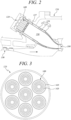
- FIG. 3 is a front diagram illustrating a burner according to the first embodiment of the present invention
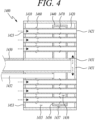
- FIG. 4 is a longitudinal cross-sectional diagram illustrating a nozzle according to the first embodiment of the present invention
- FIG. 5 is a radial cross-sectional diagram illustrating a mixing tube according to the first embodiment of the present invention.
- the nozzle 1400 may include a plurality of mixing tubes 1420 through which air and fuel flow, one or more accommodation tubes 1410 each accommodating the mixing tubes 1420, first and second fuel tubes 1431 and 1432 installed inside the accommodation tube 1410.
- a tip plate 1451 coupled to a first end or leading end of the accommodation tube 1410 and/or a rear plate 1453 coupled to a second end or rear end of the accommodation tube.
- a dispersion chamber 1440 may be disposed in the accommodation tube 1410.
- the accommodation tube 1410 may be cylindrical in shape, with a cavity formed therein. Generally, the accommodation tube 1410 may define an interior space.
- the nozzle 1400 may further include a fuel supply tube 1430 that supplies a first fuel to the accommodation tube 1410, e.g., into the interior space defined by the accommodation tube 1410.
- the first fuel may include a hydrogen-based fuel having hydrogen as a major component or a hydrocarbon-based fuel having hydrocarbon as a major component.
- the first fuel may also include a mixture of a hydrogen-based fuel and a hydrocarbon-based fuel.
- hydrocarbon-based fuel may mean a fuel having a concentration of at least 70 wt% hydrogen
- hydrocarbon-based fuel may mean a fuel having a concentration of at least 70 wt% hydrocarbon.
- the hydrocarbon-based fuel may include natural gas or the like.
- the first fuel tube 1431 may be disposed at the radial center of the accommodation tube 1410 to provide a space for the first fuel to flow.
- the first fuel tube 1431 may be arranged coaxially with a center axis of the accommodation tube 1410.
- the first fuel tube 1431 may be disposed in or extend into the interior space defined by the accommodation tube 1410.
- a first longitudinal end of the first fuel tube 1431 is connected to the fuel supply tube 1430 to receive fuel
- a second longitudinal end of the first fuel tube 1431 is connected to or in communication with a first distribution space 1435 to supply fuel to the first distribution space 1435.
- the first distribution space 1435 may extend between the tip plate 1451 and a rear plate 1453.
- the first distribution space 1435 refers to the space formed inside the accommodation tube 1410.
- the first distribution space 1435 may correspond to the interior space defined by the accommodation tube 1410.
- Leading ends of the mixing tubes 1420 may be inserted into the tip plate 1451, i.e., in respective openings formed in the tip plate 1451.
- the rear plate 1453 may be secured to the rear end (upstream side) of the accommodation tube 1410 to define or limit the first distribution space 1435 with the tip plate 1451, in particular, with respect to a longitudinal direction of the accommodation tube 1410.
- Rear ends of the mixing tubes 1420 may be inserted into the rear plate 1453, i.e., in respective openings formed in the rear plate 1453.
- the second fuel tube 1432 may be connected to the dispersion chamber 1440 to supply a second fuel to a second distribution space 1436 internally defined by the dispersion chamber 1440.
- the second fuel may include a hydrocarbon-based fuel having hydrocarbon as a major component, in particular natural gas.
- the dispersion chamber 1440 may include a housing 1456 defining the second distribution space 1436.
- the second fuel tube 1432 may arranged radially spaced apart from the first fuel tube 1431.
- the dispersion chamber 1440 is disposed within the accommodation tube 1410 so as to be combined with the second fuel tube 1432 to receive fuel from the second fuel tube 1432.
- the dispersion chamber 1440 may be arranged within the interior space defined by the accommodation tube 1410.
- the plurality of mixing tubes 1420 and the first fuel tube 1431 may pass through the dispersion chamber 1440.
- the dispersion chamber 1440 may have a cylindrical shape and may be disposed between the tip plate 1451 and the rear plate 1453.
- the dispersion chamber 1440 may be disposed adjacent to the tip plate 1451 so that the rear end (upstream side) of the dispersion chamber 1440 facing the rear end of the accommodation tube 1410 is positioned further forward (downstream side) than a longitudinal center of the accommodation tube 1410.
- a distance between the rear end of the accommodation tube 1410 and the rear end (upstream side) of the dispersion chamber 1440 may be greater than half of the distance between the rear end and the front end of the accommodation tube 1410.
- the first fuel tube 1431 optionally, may pass through the dispersion chamber 1440.
- a fuel passage 1437 may formed between the dispersion chamber 1440 and an inner circumferential wall of the accommodation tube 1410 through which the first fuel flows.
- the first fuel tube 1431 may have an opening or outlet at its front end facing the front plate 1451.
- the front end of the first fuel tube 1431 may be placed between the front end of the dispersion chamber 1440 facing the leading end of the accommodation tube 1410 and the front plate 1451. that the fuel discharged through the outlet of the first fuel tube 1431 may flow rearwardly within the accommodation tube 1410 through the fuel passage 1437.
- Each mixing tube 1420 may be formed to extend through the rear plate 1453, the dispersion chamber 1440, and the tip plate 1451. At the leading end of the mixing tube 1420, an outlet 1421 may be formed for fuel and air to exit, and at the trailing end of the mixing tube 1420, an inlet 1423 may be formed for air to enter.
- the plurality of mixing tubes 1420 are distributed inside the accommodation tube 1410, e.g., in the interior space, to accommodate and mix fuel and air and inject the fuel-air mixture into the combustion space.
- a respective mixing tube 1420 may be formed with a circular tube with a relatively small diameter to allow the fuel and air to be injected at high speed.
- Each mixing tube 1420 may be provided with a first fuel supply member 1460 that supplies a first fuel into the mixing tube 1420 and a second fuel supply member 1470 that supplies a second fuel into the mixing tube 1420.
- the first fuel supply member 1460 is connected to the first distribution space 1435 to supply the first fuel from the first distribution space 1435 into the mixing tube 1420.
- the first fuel supply member 1460 connects the first distribution space 1435 to the respective mixing tube 1420.
- the first fuel supply member 1460 may have an inlet connected to the first distribution space 1435, and an outlet 1461 connected to the mixing tube 1420.
- the first fuel supply member 1460 may be tubular in shape or, generally, may be a tube member.
- the first fuel supply member may slope forward (downstream) with respect to a radial direction of the mixing tube 1420 and protrude into the mixing tube 1420.
- a central axis of the first fuel supply member 1460 may form an acute angle smaller than 90 degrees with a central axis of the mixing tube 1420.
- the outlet 1461 of the first fuel supply member 1460 therefore, may be oriented towards the center C1 of the mixing tube 1420 and towards the front end or outlet of the mixing tube 1420.
- the first fuel supply member 1460 may be located on the rear side (upstream side) of the dispersion chamber, for example, between the rear end of the dispersion chamber 1440 and the first end of the accommodation tube 1410.
- Two or more first fuel supply members 1460 may be circumferentially disposed on the mixing tube 1420 so as to be spaced apart from each other.
- the second fuel supply member 1470 connected to the second distribution space 1436 defined by the dispersion chamber 1440 to supply the second fuel from the second distribution space 1436 into the mixing tube 1420.
- the second fuel supply member 1470 may have an inlet connected to dispersion chamber 1440, and an outlet 1471 connected to the mixing tube 1420.
- the second fuel supply member 1470 may have a tubular shape or, generally, may be a tube member.
- Two or more second fuel supply members 1470 may be circumferentially disposed on the mixing tube 1420 so as to be spaced apart from each other.
- the second fuel supply member 1470 may extend so as to be inclined toward the downstream side of the mixing tube 1420, i.e., towards the outlet of the mixing tube 1420.
- a central axis of the second fuel supply member 1470 may form an acute angle smaller than 90 degrees with a central axis of the mixing tube 1420.
- the outlet 1471 of the second fuel supply member 1470 therefore, may be oriented towards the center C1 of the mixing tube 1420 and towards the front end or outlet of the mixing tube 1420.
- a center of the outlet 1461 of the first fuel supply member 1460 may be spaced a first distance D1 from the center C1 of the mixing tube 1420, and the center of the outlet 1471 of the second fuel supply member 1470 may be spaced a second distance D2 from the center C1 of the mixing tube 1420.
- the first distance D1 may be smaller than the second distance D2.
- the outlet 1461 of the first fuel supply member 1460 is disposed closer to the center C1 of the mixing tube 1420 than the outlet 1471 of the second fuel supply member 1470, such that the first fuel may be injected toward the center portion of the mixing tube 1420, and the second fuel may be injected close to the wall surface of the mixing tube 1420.
- the first fuel is uniformly distributed inside the mixing tube 1420 and mixed with air to form a uniform fuel flow 1426 as illustrated in FIG. 8 .
- the plurality of second fuel supply members 1470 may inject the second fuel at a location adjacent to the inner circumferential wall surface of the mixing tube 1420 to form an annular concentrated fuel flow 1427 (as illustrated in FIG. 8 ) flowing along the inner circumferential wall of the mixing tube 1420.
- the second fuel may be concentrated and flows along the inner circumferential wall of the mixing tube 1420 without being substantially dispersed.
- the outlet 1471 of the second fuel supply member 1470 may be located further downstream of the outlet 1461 of the first fuel supply member 1460, such that the first fuel may be injected from the upstream side and mixed uniformly with air in the mixing tube 1420, while the second fuel may be injected toward the downstream side of the mixing tube 1420 and discharged in a concentrated state without being substantially mixed with air.
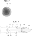
- FIG. 6 is a diagram illustrating the concentration of fuel injected from an outlet of the nozzle according to the first embodiment of the present invention
- FIG. 7 is a diagram illustrating the concentration of fuel injected from one of the mixing tubes
- FIG. 8 is a diagram illustrating a flame formed by the mixing tube according to the first embodiment of the present invention.
- FIGS. 6 to 8 when the second fuel is injected into the mixing tube 1420 through the second fuel supply member 1470, a circumferentially outwardly concentrated annulus of fuel is formed at the portion of the outlet 1421 of the mixing tube 1420 adjacent to the inner circumferential wall due to the annular concentrated fuel flow 1427, as illustrated in FIGS. 6 and 7 .
- the outer area is the area with the relatively high concentration of fuel
- the center area is the area with the relatively low concentration of fuel.
- a main flame 2100 may delaminate at the outlet of the nozzle.
- a secondary flame 2300 may be formed by the second fuel to anchor the main flame 2100 to the nozzle, preventing the flame from blowing away and maintaining a stable flame.
- the first fuel may include hydrogen, natural gas, or a mixture of hydrogen and natural gas. If the first fuel is hydrogen, the second fuel may not be supplied through the second fuel supply member 1470 because the flame may remain stable even when the second fuel is not supplied. However, if the first fuel is a mixture of hydrogen and natural gas or a natural gas fuel, the second fuel needs to be supplied through the second fuel supply member 1470 to maintain a stable flame.
- the present embodiment enables mixing and combustion of hydrocarbon-based fuel such as natural gas in the nozzle designed for combustion of hydrogen, and the flame is maintained by the second fuel regardless of the flow rate of the first fuel, so that the flow rate of the first fuel may be controlled to easily control occurrence of vibration and generation of carbon monoxide and nitrogen oxide.
- FIG. 9 is a longitudinal cross-sectional diagram illustrating a mixing tube according to a second embodiment of the present invention.
- the nozzle according to the second embodiment has the same structure as the nozzle according to the first embodiment described above, except for a second fuel supply member 1475. Therefore, a repeated description of the same configuration will be omitted.
- the second fuel supply member 1475 is connected to the dispersion chamber 1440 to inject the second fuel into the mixing tube 1420.
- the second fuel supply member 1475 may include a hole formed in the mixing tube 1420.
- two or more second fuel supply members 1475 may be circumferentially disposed on the mixing tube 1420 so as to be spaced apart from each other.
- the second fuel supply member 1475 may be realized by a hole that is formed in the circumferential wall of the mixing tube 1420.
- the hole forming the second fuel supply member 1475 may extend so as to be inclined toward the downstream side of the mixing tube 1420, i.e., towards the outlet of the mixing tube 1420. That is, an outlet of the second fuel supply member 1475 may be oriented towards the center C1 of the mixing tube 1420 and towards the front end or outlet of the mixing tube 1420.
- an inclination angle A12 of a longitudinal extension line of the second fuel supply member 1475 with the inner circumferential wall of the mixing tube 1420 may be formed to be smaller than that an inclination angle A11 of a longitudinal extension line of the first fuel supply member 1460 with the inner circumferential wall of the mixing tube 1420.
- the inclination angle A11 may range from 45 degrees to 90 degrees
- the inclination angle A12 may range from 45 degrees to 10 degrees.
- the second fuel supply member 1475 may be formed to be more inclined toward the downstream side, i.e., the outlet of the mixing tube 1420, to facilitate the formation of an annular concentrated fuel flow 1427 as the fuel injected from the second fuel supply member 1475 flows along the inner circumferential wall of the mixing tube 1420.
- FIG. 10 is a longitudinal sectional diagram illustrating a mixing tube according to a third embodiment of the present invention.
- the nozzle according to the third embodiment has the same structure as the nozzle according to the first embodiment described above, except for a second fuel supply member 1480. Therefore, a repeated description of the same configuration will be omitted.
- the second fuel supply member 1480 is connected to the dispersion chamber 1440 to inject the second fuel into the mixing tube 1420.
- the second fuel supply member 1480 is tubular in shape.
- two or more second fuel supply tubes 1480 may be circumferentially disposed on the mixing tube 1420 so as to be spaced apart from each other.
- the second fuel supply member 1480 may include a first portion 1481 extending to be inclined downstream of the mixing tube 1420, and a second portion 1482 bent from the first portion 1481 toward the longitudinal direction of the mixing tube 1420. That is, the first portion 1481 may extend inclined relative to a central axis of the mixing tube 1420, and the second portion 1483 may extend parallel or substantially parallel to the central axis of the mixing tube 1420.
- the first portion 1481 may extend toward the radial center of the mixing tube at an inclination angle toward the downstream side of the mixing tube 1420.
- the second portion 1482 may extend in the longitudinal direction of the mixing tube 1420 and, optionally, may abut against the inner circumferential wall of the mixing tube 1420.
- An outlet 1483 of the second fuel supply member 1480 is formed at the second portion 1482, and the outlet 1483 may be disposed perpendicular to the longitudinal direction of the mixing tube 1420. That is, the outlet 1483 of the second fuel supply member 1480 may face the outlet of the mixing tube 1420.
- the second fuel injected from the second fuel supply member 2470 has only a velocity vector in the longitudinal direction of the mixing tube 1420, e.g., parallel to the central axis of the mixing tube 1420, and may therefore stably form an annular concentrated fuel flow 1427 as the second fuel flows along the inner circumferential wall of the mixing tube 1420.
- FIG. 11 is a longitudinal sectional diagram illustrating a mixing tube according to a fourth embodiment of the present invention.
- the nozzle according to the fourth embodiment has the same structure as the nozzle according to the first embodiment described above, except for a second fuel supply member 1490. Therefore, a repeated description of the same configuration will be omitted.
- the second fuel supply member 1490 is connected to the dispersion chamber 1440 to inject the second fuel into the mixing tube 1420.
- the second fuel supply member 1490 is tubular in shape.
- two or more second fuel supply tubes 1490 may be circumferentially disposed on the mixing tube 1420 so as to be spaced apart from each other.
- a guide portion 1492 is formed for injecting the second fuel toward an inner circumferential wall of the mixing tube 1420.
- the guide portion 1492 is curved in an arc or inclined toward the inner circumferential wall surface of the mixing tube 1420 so as to induce the second fuel to form a flow toward the inner circumferential wall surface of the mixing tube 1420.
- an outlet 1491 of the second fuel supply member 1490 is formed to be inclined at an inclination angle A21 with respect to the inner circumferential wall of the mixing tube 1420, wherein the inclination angle A21 may be an acute angle.
- the inclination angle A21 may range from 30 degrees to 80 degrees.
- the second fuel is injected toward the inner circumferential wall of the mixing tube 1420, so that a flow of the second fuel may be in close contact with the inner circumferential surface of the mixing tube 1420 to form a more concentrated fuel flow 1427.
Landscapes
- Engineering & Computer Science (AREA)
- Chemical & Material Sciences (AREA)
- Combustion & Propulsion (AREA)
- Mechanical Engineering (AREA)
- General Engineering & Computer Science (AREA)
- Gas Burners (AREA)
Applications Claiming Priority (1)
| Application Number | Priority Date | Filing Date | Title |
|---|---|---|---|
| KR1020230177751A KR102863422B1 (ko) | 2023-12-08 | 2023-12-08 | 연소기용 노즐, 연소기, 및 이를 포함하는 가스 터빈 |
Publications (1)
| Publication Number | Publication Date |
|---|---|
| EP4567331A1 true EP4567331A1 (fr) | 2025-06-11 |
Family
ID=93432346
Family Applications (1)
| Application Number | Title | Priority Date | Filing Date |
|---|---|---|---|
| EP24211033.6A Pending EP4567331A1 (fr) | 2023-12-08 | 2024-11-06 | Buse de chambre de combustion, chambre de combustion et turbine à gaz comprenant celle-ci |
Country Status (3)
| Country | Link |
|---|---|
| US (1) | US20250189134A1 (fr) |
| EP (1) | EP4567331A1 (fr) |
| KR (1) | KR102863422B1 (fr) |
Citations (8)
| Publication number | Priority date | Publication date | Assignee | Title |
|---|---|---|---|---|
| JPS6082724A (ja) * | 1983-10-13 | 1985-05-10 | Agency Of Ind Science & Technol | ガスタ−ビン燃焼器 |
| US20110083439A1 (en) * | 2009-10-08 | 2011-04-14 | General Electric Corporation | Staged Multi-Tube Premixing Injector |
| US20130074510A1 (en) * | 2011-09-25 | 2013-03-28 | General Electric Company | Combustor and method for supplying fuel to a combustor |
| US20130232979A1 (en) * | 2012-03-12 | 2013-09-12 | General Electric Company | System for enhancing mixing in a multi-tube fuel nozzle |
| US20130239581A1 (en) * | 2012-03-19 | 2013-09-19 | General Electric Company | Systems and Methods for Preventing Flashback in a Combustor Assembly |
| KR20200027894A (ko) | 2018-09-05 | 2020-03-13 | 미츠비시 히타치 파워 시스템즈 가부시키가이샤 | 가스 터빈 연소기 |
| US20230213195A1 (en) * | 2022-01-06 | 2023-07-06 | Doosan Enerbility Co., Ltd | Combustor nozzle, combustor, and gas turbine including the same |
| US20230266011A1 (en) * | 2022-02-21 | 2023-08-24 | Doosan Enerbility Co., Ltd. | Combustor nozzle, combustor, and gas turbine including the same |
Family Cites Families (7)
| Publication number | Priority date | Publication date | Assignee | Title |
|---|---|---|---|---|
| US5284438A (en) * | 1992-01-07 | 1994-02-08 | Koch Engineering Company, Inc. | Multiple purpose burner process and apparatus |
| EP1710506A2 (fr) * | 1999-12-15 | 2006-10-11 | Osaka Gas Co., Ltd. | Brûleur, moteur de turbine à gaz et système de cogénération |
| US8438851B1 (en) * | 2012-01-03 | 2013-05-14 | General Electric Company | Combustor assembly for use in a turbine engine and methods of assembling same |
| US20160186663A1 (en) * | 2014-12-30 | 2016-06-30 | General Electric Company | Pilot nozzle in gas turbine combustor |
| EP3051206B1 (fr) * | 2015-01-28 | 2019-10-30 | Ansaldo Energia Switzerland AG | Agencement de combustion séquentielle d'une turbine à gaz avec un mélangeur et un amortisseur |
| KR101986729B1 (ko) | 2017-08-22 | 2019-06-07 | 두산중공업 주식회사 | 실 영역 집중냉각을 위한 냉각유로 구조 및 이를 포함하는 가스 터빈용 연소기 |
| KR102595333B1 (ko) * | 2021-09-17 | 2023-10-27 | 두산에너빌리티 주식회사 | 연소기 및 이를 포함하는 가스터빈 |
-
2023
- 2023-12-08 KR KR1020230177751A patent/KR102863422B1/ko active Active
-
2024
- 2024-10-16 US US18/917,649 patent/US20250189134A1/en active Pending
- 2024-11-06 EP EP24211033.6A patent/EP4567331A1/fr active Pending
Patent Citations (8)
| Publication number | Priority date | Publication date | Assignee | Title |
|---|---|---|---|---|
| JPS6082724A (ja) * | 1983-10-13 | 1985-05-10 | Agency Of Ind Science & Technol | ガスタ−ビン燃焼器 |
| US20110083439A1 (en) * | 2009-10-08 | 2011-04-14 | General Electric Corporation | Staged Multi-Tube Premixing Injector |
| US20130074510A1 (en) * | 2011-09-25 | 2013-03-28 | General Electric Company | Combustor and method for supplying fuel to a combustor |
| US20130232979A1 (en) * | 2012-03-12 | 2013-09-12 | General Electric Company | System for enhancing mixing in a multi-tube fuel nozzle |
| US20130239581A1 (en) * | 2012-03-19 | 2013-09-19 | General Electric Company | Systems and Methods for Preventing Flashback in a Combustor Assembly |
| KR20200027894A (ko) | 2018-09-05 | 2020-03-13 | 미츠비시 히타치 파워 시스템즈 가부시키가이샤 | 가스 터빈 연소기 |
| US20230213195A1 (en) * | 2022-01-06 | 2023-07-06 | Doosan Enerbility Co., Ltd | Combustor nozzle, combustor, and gas turbine including the same |
| US20230266011A1 (en) * | 2022-02-21 | 2023-08-24 | Doosan Enerbility Co., Ltd. | Combustor nozzle, combustor, and gas turbine including the same |
Also Published As
| Publication number | Publication date |
|---|---|
| KR102863422B1 (ko) | 2025-09-22 |
| US20250189134A1 (en) | 2025-06-12 |
| KR20250088089A (ko) | 2025-06-17 |
Similar Documents
| Publication | Publication Date | Title |
|---|---|---|
| KR102403750B1 (ko) | 멀티 튜브를 갖는 연소기용 노즐, 연소기, 및 이를 포함하는 가스 터빈 | |
| US11913647B2 (en) | Combustor nozzle, combustor, and gas turbine including the same | |
| KR102632603B1 (ko) | 연소기용 노즐, 연소기, 및 이를 포함하는 가스 터빈 | |
| US11592180B2 (en) | Combustor nozzle, combustor, and gas turbine including same | |
| US11359813B2 (en) | Combustor and gas turbine including the same | |
| US12146661B2 (en) | Combustor nozzle, combustor, and gas turbine including the same | |
| KR102721786B1 (ko) | 연소기용 노즐, 연소기 및 이를 포함하는 가스 터빈 | |
| EP4567331A1 (fr) | Buse de chambre de combustion, chambre de combustion et turbine à gaz comprenant celle-ci | |
| EP4563890A1 (fr) | Buse de chambre de combustion, chambre de combustion et turbine à gaz comprenant celle-ci | |
| US12359815B2 (en) | Combustor nozzle, combustor, and gas turbine including same | |
| US12352444B2 (en) | Combustor nozzle, combustor, and gas turbine including same | |
| KR102791926B1 (ko) | 연소기용 노즐, 연소기, 및 이를 포함하는 가스 터빈 | |
| KR102697366B1 (ko) | 연소기용 노즐, 연소기, 및 이를 포함하는 가스 터빈 | |
| KR102660055B1 (ko) | 연소기용 노즐, 연소기, 및 이를 포함하는 가스 터빈 | |
| US12305859B2 (en) | Nozzle assembly, combustor, and gas turbine including same | |
| EP4212778A1 (fr) | Buse de chambre de combustion | |
| KR20250084053A (ko) | 연소기 노즐과 이를 포함하는 연소기 및 가스터빈 |
Legal Events
| Date | Code | Title | Description |
|---|---|---|---|
| PUAI | Public reference made under article 153(3) epc to a published international application that has entered the european phase |
Free format text: ORIGINAL CODE: 0009012 |
|
| STAA | Information on the status of an ep patent application or granted ep patent |
Free format text: STATUS: REQUEST FOR EXAMINATION WAS MADE |
|
| 17P | Request for examination filed |
Effective date: 20241106 |
|
| AK | Designated contracting states |
Kind code of ref document: A1 Designated state(s): AL AT BE BG CH CY CZ DE DK EE ES FI FR GB GR HR HU IE IS IT LI LT LU LV MC ME MK MT NL NO PL PT RO RS SE SI SK SM TR |