EP4567450A1 - Système radar à entrées multiples et sorties multiples - Google Patents
Système radar à entrées multiples et sorties multiples Download PDFInfo
- Publication number
- EP4567450A1 EP4567450A1 EP23307158.8A EP23307158A EP4567450A1 EP 4567450 A1 EP4567450 A1 EP 4567450A1 EP 23307158 A EP23307158 A EP 23307158A EP 4567450 A1 EP4567450 A1 EP 4567450A1
- Authority
- EP
- European Patent Office
- Prior art keywords
- phase
- transmit
- scrambling
- phase rotation
- rotator
- Prior art date
- Legal status (The legal status is an assumption and is not a legal conclusion. Google has not performed a legal analysis and makes no representation as to the accuracy of the status listed.)
- Granted
Links
Images


Classifications
-
- G—PHYSICS
- G01—MEASURING; TESTING
- G01S—RADIO DIRECTION-FINDING; RADIO NAVIGATION; DETERMINING DISTANCE OR VELOCITY BY USE OF RADIO WAVES; LOCATING OR PRESENCE-DETECTING BY USE OF THE REFLECTION OR RERADIATION OF RADIO WAVES; ANALOGOUS ARRANGEMENTS USING OTHER WAVES
- G01S7/00—Details of systems according to groups G01S13/00, G01S15/00, G01S17/00
- G01S7/02—Details of systems according to groups G01S13/00, G01S15/00, G01S17/00 of systems according to group G01S13/00
- G01S7/35—Details of non-pulse systems
- G01S7/352—Receivers
-
- G—PHYSICS
- G01—MEASURING; TESTING
- G01S—RADIO DIRECTION-FINDING; RADIO NAVIGATION; DETERMINING DISTANCE OR VELOCITY BY USE OF RADIO WAVES; LOCATING OR PRESENCE-DETECTING BY USE OF THE REFLECTION OR RERADIATION OF RADIO WAVES; ANALOGOUS ARRANGEMENTS USING OTHER WAVES
- G01S7/00—Details of systems according to groups G01S13/00, G01S15/00, G01S17/00
- G01S7/02—Details of systems according to groups G01S13/00, G01S15/00, G01S17/00 of systems according to group G01S13/00
- G01S7/023—Interference mitigation, e.g. reducing or avoiding non-intentional interference with other HF-transmitters, base station transmitters for mobile communication or other radar systems, e.g. using electro-magnetic interference [EMI] reduction techniques
- G01S7/0233—Avoidance by phase multiplex
-
- G—PHYSICS
- G01—MEASURING; TESTING
- G01S—RADIO DIRECTION-FINDING; RADIO NAVIGATION; DETERMINING DISTANCE OR VELOCITY BY USE OF RADIO WAVES; LOCATING OR PRESENCE-DETECTING BY USE OF THE REFLECTION OR RERADIATION OF RADIO WAVES; ANALOGOUS ARRANGEMENTS USING OTHER WAVES
- G01S7/00—Details of systems according to groups G01S13/00, G01S15/00, G01S17/00
- G01S7/02—Details of systems according to groups G01S13/00, G01S15/00, G01S17/00 of systems according to group G01S13/00
-
- G—PHYSICS
- G01—MEASURING; TESTING
- G01S—RADIO DIRECTION-FINDING; RADIO NAVIGATION; DETERMINING DISTANCE OR VELOCITY BY USE OF RADIO WAVES; LOCATING OR PRESENCE-DETECTING BY USE OF THE REFLECTION OR RERADIATION OF RADIO WAVES; ANALOGOUS ARRANGEMENTS USING OTHER WAVES
- G01S13/00—Systems using the reflection or reradiation of radio waves, e.g. radar systems; Analogous systems using reflection or reradiation of waves whose nature or wavelength is irrelevant or unspecified
- G01S13/02—Systems using reflection of radio waves, e.g. primary radar systems; Analogous systems
- G01S13/06—Systems determining position data of a target
- G01S13/08—Systems for measuring distance only
-
- G—PHYSICS
- G01—MEASURING; TESTING
- G01S—RADIO DIRECTION-FINDING; RADIO NAVIGATION; DETERMINING DISTANCE OR VELOCITY BY USE OF RADIO WAVES; LOCATING OR PRESENCE-DETECTING BY USE OF THE REFLECTION OR RERADIATION OF RADIO WAVES; ANALOGOUS ARRANGEMENTS USING OTHER WAVES
- G01S13/00—Systems using the reflection or reradiation of radio waves, e.g. radar systems; Analogous systems using reflection or reradiation of waves whose nature or wavelength is irrelevant or unspecified
- G01S13/02—Systems using reflection of radio waves, e.g. primary radar systems; Analogous systems
- G01S13/06—Systems determining position data of a target
- G01S13/08—Systems for measuring distance only
- G01S13/32—Systems for measuring distance only using transmission of continuous waves, whether amplitude-, frequency-, or phase-modulated, or unmodulated
- G01S13/325—Systems for measuring distance only using transmission of continuous waves, whether amplitude-, frequency-, or phase-modulated, or unmodulated using transmission of coded signals, e.g. P.S.K. signals
-
- G—PHYSICS
- G01—MEASURING; TESTING
- G01S—RADIO DIRECTION-FINDING; RADIO NAVIGATION; DETERMINING DISTANCE OR VELOCITY BY USE OF RADIO WAVES; LOCATING OR PRESENCE-DETECTING BY USE OF THE REFLECTION OR RERADIATION OF RADIO WAVES; ANALOGOUS ARRANGEMENTS USING OTHER WAVES
- G01S13/00—Systems using the reflection or reradiation of radio waves, e.g. radar systems; Analogous systems using reflection or reradiation of waves whose nature or wavelength is irrelevant or unspecified
- G01S13/02—Systems using reflection of radio waves, e.g. primary radar systems; Analogous systems
- G01S13/06—Systems determining position data of a target
- G01S13/08—Systems for measuring distance only
- G01S13/32—Systems for measuring distance only using transmission of continuous waves, whether amplitude-, frequency-, or phase-modulated, or unmodulated
- G01S13/34—Systems for measuring distance only using transmission of continuous waves, whether amplitude-, frequency-, or phase-modulated, or unmodulated using transmission of continuous, frequency-modulated waves while heterodyning the received signal, or a signal derived therefrom, with a locally-generated signal related to the contemporaneously transmitted signal
- G01S13/343—Systems for measuring distance only using transmission of continuous waves, whether amplitude-, frequency-, or phase-modulated, or unmodulated using transmission of continuous, frequency-modulated waves while heterodyning the received signal, or a signal derived therefrom, with a locally-generated signal related to the contemporaneously transmitted signal using sawtooth modulation
-
- G—PHYSICS
- G01—MEASURING; TESTING
- G01S—RADIO DIRECTION-FINDING; RADIO NAVIGATION; DETERMINING DISTANCE OR VELOCITY BY USE OF RADIO WAVES; LOCATING OR PRESENCE-DETECTING BY USE OF THE REFLECTION OR RERADIATION OF RADIO WAVES; ANALOGOUS ARRANGEMENTS USING OTHER WAVES
- G01S13/00—Systems using the reflection or reradiation of radio waves, e.g. radar systems; Analogous systems using reflection or reradiation of waves whose nature or wavelength is irrelevant or unspecified
- G01S13/02—Systems using reflection of radio waves, e.g. primary radar systems; Analogous systems
- G01S13/06—Systems determining position data of a target
- G01S13/42—Simultaneous measurement of distance and other co-ordinates
-
- G—PHYSICS
- G01—MEASURING; TESTING
- G01S—RADIO DIRECTION-FINDING; RADIO NAVIGATION; DETERMINING DISTANCE OR VELOCITY BY USE OF RADIO WAVES; LOCATING OR PRESENCE-DETECTING BY USE OF THE REFLECTION OR RERADIATION OF RADIO WAVES; ANALOGOUS ARRANGEMENTS USING OTHER WAVES
- G01S13/00—Systems using the reflection or reradiation of radio waves, e.g. radar systems; Analogous systems using reflection or reradiation of waves whose nature or wavelength is irrelevant or unspecified
- G01S13/87—Combinations of radar systems, e.g. primary radar and secondary radar
- G01S13/878—Combination of several spaced transmitters or receivers of known location for determining the position of a transponder or a reflector
-
- G—PHYSICS
- G01—MEASURING; TESTING
- G01S—RADIO DIRECTION-FINDING; RADIO NAVIGATION; DETERMINING DISTANCE OR VELOCITY BY USE OF RADIO WAVES; LOCATING OR PRESENCE-DETECTING BY USE OF THE REFLECTION OR RERADIATION OF RADIO WAVES; ANALOGOUS ARRANGEMENTS USING OTHER WAVES
- G01S13/00—Systems using the reflection or reradiation of radio waves, e.g. radar systems; Analogous systems using reflection or reradiation of waves whose nature or wavelength is irrelevant or unspecified
- G01S13/88—Radar or analogous systems specially adapted for specific applications
-
- G—PHYSICS
- G01—MEASURING; TESTING
- G01S—RADIO DIRECTION-FINDING; RADIO NAVIGATION; DETERMINING DISTANCE OR VELOCITY BY USE OF RADIO WAVES; LOCATING OR PRESENCE-DETECTING BY USE OF THE REFLECTION OR RERADIATION OF RADIO WAVES; ANALOGOUS ARRANGEMENTS USING OTHER WAVES
- G01S13/00—Systems using the reflection or reradiation of radio waves, e.g. radar systems; Analogous systems using reflection or reradiation of waves whose nature or wavelength is irrelevant or unspecified
- G01S13/88—Radar or analogous systems specially adapted for specific applications
- G01S13/93—Radar or analogous systems specially adapted for specific applications for anti-collision purposes
-
- G—PHYSICS
- G01—MEASURING; TESTING
- G01S—RADIO DIRECTION-FINDING; RADIO NAVIGATION; DETERMINING DISTANCE OR VELOCITY BY USE OF RADIO WAVES; LOCATING OR PRESENCE-DETECTING BY USE OF THE REFLECTION OR RERADIATION OF RADIO WAVES; ANALOGOUS ARRANGEMENTS USING OTHER WAVES
- G01S13/00—Systems using the reflection or reradiation of radio waves, e.g. radar systems; Analogous systems using reflection or reradiation of waves whose nature or wavelength is irrelevant or unspecified
- G01S13/88—Radar or analogous systems specially adapted for specific applications
- G01S13/93—Radar or analogous systems specially adapted for specific applications for anti-collision purposes
- G01S13/931—Radar or analogous systems specially adapted for specific applications for anti-collision purposes of land vehicles
-
- G—PHYSICS
- G01—MEASURING; TESTING
- G01S—RADIO DIRECTION-FINDING; RADIO NAVIGATION; DETERMINING DISTANCE OR VELOCITY BY USE OF RADIO WAVES; LOCATING OR PRESENCE-DETECTING BY USE OF THE REFLECTION OR RERADIATION OF RADIO WAVES; ANALOGOUS ARRANGEMENTS USING OTHER WAVES
- G01S13/00—Systems using the reflection or reradiation of radio waves, e.g. radar systems; Analogous systems using reflection or reradiation of waves whose nature or wavelength is irrelevant or unspecified
- G01S13/88—Radar or analogous systems specially adapted for specific applications
- G01S13/93—Radar or analogous systems specially adapted for specific applications for anti-collision purposes
- G01S13/937—Radar or analogous systems specially adapted for specific applications for anti-collision purposes of marine craft
-
- G—PHYSICS
- G01—MEASURING; TESTING
- G01S—RADIO DIRECTION-FINDING; RADIO NAVIGATION; DETERMINING DISTANCE OR VELOCITY BY USE OF RADIO WAVES; LOCATING OR PRESENCE-DETECTING BY USE OF THE REFLECTION OR RERADIATION OF RADIO WAVES; ANALOGOUS ARRANGEMENTS USING OTHER WAVES
- G01S7/00—Details of systems according to groups G01S13/00, G01S15/00, G01S17/00
- G01S7/02—Details of systems according to groups G01S13/00, G01S15/00, G01S17/00 of systems according to group G01S13/00
- G01S7/03—Details of HF subsystems specially adapted therefor, e.g. common to transmitter and receiver
-
- G—PHYSICS
- G01—MEASURING; TESTING
- G01S—RADIO DIRECTION-FINDING; RADIO NAVIGATION; DETERMINING DISTANCE OR VELOCITY BY USE OF RADIO WAVES; LOCATING OR PRESENCE-DETECTING BY USE OF THE REFLECTION OR RERADIATION OF RADIO WAVES; ANALOGOUS ARRANGEMENTS USING OTHER WAVES
- G01S7/00—Details of systems according to groups G01S13/00, G01S15/00, G01S17/00
- G01S7/02—Details of systems according to groups G01S13/00, G01S15/00, G01S17/00 of systems according to group G01S13/00
- G01S7/35—Details of non-pulse systems
Definitions
- the present disclosure relates to a multiple input multiple output (MIMO) radar system, a corresponding transmitter apparatus, a corresponding receiver apparatus, a method and an automotive vehicle comprising the MIMO radar system.
- MIMO multiple input multiple output
- a multiple input multiple output, MIMO, radar system comprising: a plurality of transmit paths wherein each transmit path is configured to transmit a corresponding output radar signal for detection and ranging, wherein each transmit path comprises: a transmit antenna; a phase rotator; and wherein the phase rotator is configured to, for each output radar signal, apply: a Doppler Division Multiplexing, DDM, phase rotation to each output radar signal prior to transmission by the transmit antenna, and, a scrambling phase rotation to each output radar signal prior to transmission by the transmit antenna, wherein: the DDM phase rotation applied by each phase rotator of each transmit path is according to a DDM phase schedule; and the scrambling phase rotation applied by each phase rotator of each transmit path is the same as the scrambling phase rotation applied by each other phase rotator of the other transmit paths; and wherein the MIMO system further comprises a plurality of receive paths configured to receive reflected versions of the output radar signals from a reflector.
- DDM Doppler Division Multiplexing
- the MIMO system
- the transmitted radar signals may be frequency modulated continuous wave radar signals.
- the MIMO radar system may comprise a phase rotation controller configured to control the DDM phase rotation and the scrambling phase rotation applied by each of the phase rotators of each of the transmit paths.
- the MIMO radar system may be configured to cause each transmitter to transmit a set of radar signals wherein the set of radar signals comprises a predetermined number of consecutively transmitted radar signals and wherein the scrambling phase rotation is different for each transmitted radar signal in the set of transmitted radar signals.
- the scrambling phase rotations may be selected to cover at least a subset of the full range of possible phase rotations of the phase rotator.
- the scrambling phase rotations may be selected to cover the full range of possible phase rotations of the phase rotator.
- the phase rotation controller may be configured to apply a modulo operation to the phase offsets in order to maintain values within the programmable range of the phase rotators.
- the scrambling phase rotations may be one of a random; and a pseudo-randomly determined phase rotation.
- a transmission apparatus of a multiple input multiple output, MIMO, radar system comprising: a plurality of transmit paths wherein each transmit path is configured to transmit a corresponding output radar signal for detection and ranging, wherein each transmit path comprises: a transmit antenna; a phase rotator; and wherein the phase rotator is configured to, for each output radar signal, apply: a Doppler Division Multiplexing, DDM, phase rotation to each output radar signal prior to transmission by the transmit antenna, and, a scrambling phase rotation to each output radar signal prior to transmission by the transmit antenna, wherein: the DDM phase rotation applied by each phase rotator of each transmit path is according to a DDM phase schedule; and the scrambling phase rotation applied by each phase rotator of each transmit path is the same as the scrambling phase rotation applied by each other phase rotator of the other transmit paths.
- DDM Doppler Division Multiplexing
- the scrambling phase rotation applied by each phase rotator of each transmit path is the same as the scrambling phase rotation applied by each other phase
- a method of performing ranging and detection using a multiple input multiple output, MIMO, radar system that comprises a plurality of transmit paths wherein each transmit path comprises a transmit antenna and a phase rotator, the method comprising for each transit path: receiving an output radar signal at the phase rotator; applying, by way of the phase rotator, a Doppler Division Multiplexing (DDM) phase rotation to each output radar signal prior to transmission by a transmit antenna; applying, by way of the phase rotator, a scrambling phase rotation to each output radar signal prior to transmission by the transmit antenna, wherein: the DDM phase rotation applied by each phase rotator of each transmit path is according to a DDM phase schedule; the scrambling phase rotation applied by each phase rotator of each transmit path is the same as the scrambling phase rotation applied by each other phase rotator of the other transmit paths; transmitting the phase-rotated output radar signal by way of the transmit antenna, the method further comprising, at a plurality of receive
- DDM Doppler Division Multiplexing
- an automotive vehicle comprising the radar system of any of the first aspect.
- FIG. 1 shows a MIMO radar system 100 that comprises multiple transmit antennas 101A - 101C each in a different transmit path 102A - 102C.
- Radar signals transmitted by the transmit antennas 101A - 101C can be encoded using Doppler Division Multiplexing (DDM) techniques.
- the transmit paths 102A - 102C form part of a transmitter apparatus 107 of the transmit side.
- the encoded signals are transmitted from the plurality of transmit antennas 101A - 101C simultaneously.
- a receive antenna 103A- 103D of a receive path 104A - 104D is exposed to the sum of transmitted signals via reflecting objects.
- the individual output radar signals can be recovered by a receiver apparatus 108 on the receive side.
- the offset frequencies are on the order of the Doppler frequencies experienced in 79 GHz radar systems and automotive scenarios.
- a sequence of consecutively emitted Frequency Modulated Continuous Wave (FMCW) radar signals is transmitted.
- FMCW Frequency Modulated Continuous Wave
- a 2D Fast Fourier Transform (FFT) operation can be carried out to estimate distance and relative the radial velocity (Doppler frequency) of the reflector from which the output radar signals have been reflected prior to being received at the receive side.
- Doppler frequency radial velocity
- the maximum Doppler frequency that can be unambiguously measured is inversely proportional to the duration of a single frequency ramp (also sometimes referred to as a "chirp") of an FMCW signal, including settling time and time of flight.
- the DDM frequency shifts have to be smaller than this maximum Doppler frequency. Due to this, the sampling theorem is directly fulfilled and the frequency offset can be realized by applying a phase rotation to each frequency ramp. Similar phase offsets may be applied for radar techniques other than FMCW in order to obtain similar results. For example, the technique could be equally applied to at least phase modulated continuous (PMCW) waveforms or orthogonal frequency division multiplexing (OFDM) waveforms.
- FMCW is used herein by way of example only.
- Figure 2 shows an example idealized Doppler spectrum for a single reflector where DDM has been employed with four transmitters.
- Phase errors can be introduced into a transmitted signal in a number of ways.
- a phase rotator 105A - 105C used to set the phase of an output signal may introduce phase error and so may coupling between transmitters in a die with multiple transmitters.
- Other contributors to phase errors and the resulting spurs may also exist. Since the phase error of an applied phase is correlated to the desired phase, the repetitive usage of the same phase leads to a repetitive occurrence of the same phase error. This leads to spurious frequencies in the Doppler spectrum arising. Spurious frequencies in the Doppler spectrum can exceed the thermal noise floor and degrade the sensitivity of the radar in proximity to strong reflectors.
- Figure 3 depicts the presence of spurs resulting from phase errors.
- only one transmitter is activated and coded.
- the other three transmitters are switched off.
- the largest peak (tone) is the only desired signal.
- the rest of the tones are unwanted spurs.
- the spurs overlap with the Doppler offsets of where the other transmitters may be expected to be observed.
- the spurious frequencies are undesired as they can be mistaken as true reflectors leading to ghost objects.
- Increasing the detection threshold is not a solution, as the dynamic range of the radar system would be compromised by doing this. For example, if the detection threshold were increased, a toddler beside a truck could go undetected.
- the present disclosure provides a solution that lowers the spurs by spreading their energy over the Doppler spectrum.
- a MIMO radar system 100 that comprises a plurality of transmit paths (3 in this case) 102A - 102C in a transmit apparatus 107 on the transmit side and a plurality of receive paths (4 in this case) 104A - 104D in a receiver apparatus 108 on the receiver side.
- the transmit and receive sides may have the same number or a different number of transmit and receive paths.
- transceivers may be used which provide both the transmitter and receiver functionalities.
- Circulators or any other suitable means may be used to direct outgoing and incoming radar signals along the appropriate transmit path 102A - 102C or receive path 104A - 104D.
- the transmit antennas 101A - 101C and receive antennas 103A - 103D are separate devices.
- Each transmit path also comprises a phase rotator 105A - 105C that is configured to apply a phase rotation to a radar signal for output by the transmit antenna 101A - 101C of the same transmit path 102A - 102C.
- Each phase rotator 105A - 105C may apply phase rotation to a radar signal received from a signal generator 110 using any suitable technique.
- the phase rotators 105A - 105C of the radar system 100 may be controlled by a common phase rotation controller 106.
- the phase rotation controller 106 may be a dedicated controller for controlling the phase of output radar signals or it may be part of a wider controller for the radar system 100.
- phase rotation controller 106 may be part of an even more over-arching device, such as the controller of an automotive vehicle.
- each phase rotator 105A - 105C may be controlled by its own separate dedicated phase rotation controller.
- Figure 4 shows an example of Doppler Division Multiplexing (DDM) phase rotations applied to each frequency ramp in a set of consecutively output frequency ramps 401 for each of four different transmitters in an FMCW MIMO radar system.
- Each phase rotator is configured to apply to each output radar signal a DDM phase rotation prior to transmission by the transmit antenna.
- Figure 4 further shows that the phases of the consecutively output radar signals of each of the second through fourth transmit paths change according to different patterns compared to each other.
- the phase of the second consecutively emitted radar signals from the second transmit path changes by 90 degrees per consecutively emitted radar signal.
- the phase of the third consecutively emitted radar signals from the third transmit path changes by 180 degrees per consecutively emitted radar signal.
- the phase of the fourth consecutively emitted radar signals from the fourth transmit path changes by - 90 degrees per consecutively emitted radar signal.
- the transmit antenna of each transmit path is configured to transmit a plurality of consecutively output radar signals
- the phase difference between consecutively output radar signals is different for each transmit paths.
- the phase shifts applied to each transmitter are integer multiples of 90 degrees. That is, the DDM phase rotations are applied according to a DDM phase schedule.
- Each phase rotator 105A - 105C is further configured to apply to each output radar signal a scrambling phase rotation.
- the scrambling phase rotation applied by each phase rotator 105A - 105C of each transmit path is the same as the scrambling phase rotation applied by each other phase rotator 105A - 105C of the other transmit paths.
- the scrambling phase may be different for each consecutive emission such that the energy of the spurs is spread over the Doppler spectrum.
- the undesirable spurs can be spread over the Doppler spectrum, thereby reducing the likelihood of any clear spurs developing above inherent the noise of the system.
- phase rotations are applied to the output radar signals prior to transmission by the transmit antennas 101A - 101C.
- Each phase rotator 105A -105C may use a single phase rotation component to apply both the DDM phase rotation and the scrambling phase rotation such that an amalgamated phase rotation is applied to the output radar signals simultaneously.
- phase rotation applied by the phase rotators 105A - 105C may be controlled by one or more phase rotation controllers 106.
- a single phase rotation controller 106 may control all of the phase rotators 105A - 105C.
- a plurality of phase rotation controllers may be provided where each phase rotator is controlled by a different phase rotation controller.
- the or each phase rotation controller 106 may be configured to control the phase according to a look-up table which contains the phases that should be applied to the output radar signals of the transmit apparatus 107.
- the or each phase controller 106 may control the phase rotators in any other suitable manner.
- the scrambling phase may be selected according to a random number generation technique or according to a pseudo-random number technique. That is, the scrambling phase may be random or pseudo-random.
- Figure 5 shows an example of the scrambling phase rotations applied to each frequency ramp in a set of consecutively output frequency ramps for each of four different transmitters in an FMCW MIMO radar system.
- the scrambling phase applied to each subsequent output radar signal may be different, as demonstrated in Figure 5 where the different scrambling phase shifts are represented by the letters A - H.
- the scrambling phases applied to each transmitted radar signal at a same particular time, however, will all be the same.
- the scrambling phase is A in each case.
- the scrambling phases applied across a whole set of a plurality of output radar signals may be selected to cover at least a subset of the full range of possible phase rotations of the phase rotator 105A - 105C. That is, scrambling phase shifts A - H may comprise frequencies over a predefined range.
- the scrambling phases applied across a whole set of a plurality of output radar signals may be selected to cover the full range of possible phase rotations of the phrase rotator 105A - 105C. The wider the range of phases over which the scrambling phases are selected, the more spread-out the energy of the spurs will be.
- the scrambling phases may be selected from amongst the frequencies of 0 - 90 degrees; 0 - 180 degrees, 0 - 270 degrees or another subset of possible phase rotations. In other examples, the scrambling phases may be selected from across the full range of possible phase rotations of 0 - 360 degrees.
- the or each phase rotation controller 106 may be configured to apply a modulo operation to the phase offsets in order to maintain the values within a programmed range of the possible phase rotations. Practical limitations may further limit the precise phases that the scrambling phase may take. For example, an N bit phase rotator can produce 2 N different phases.
- the scrambling sequence is a pseudo-random sequence that takes values between 0 and 2 N -1. The random value may be added to the desired codes with the modulo operation to stay in range.
- the scrambling phase may not be a continuous scale and may preferably cover the full range of 360 degrees.
- the scrambling phase for each consecutively output radar signal may be predetermined and built into a look-up table.
- the or each phase rotation controller 106 may be configured to generate the random or pseudo random phase of the scrambling phase rotation dynamically for each output radar signal and apply this in addition to the DDM phase rotation.
- Each transmit path may further comprise one or more power amplifiers 111 configured to amplify the output radar signals prior to transmission by the transmit antennas 101A - 101C.
- the power amplifiers 111 are shown in figure 1 as being disposed between the phase rotators 105A - 105C and the transmit antennas, however, alternative configurations may also be envisioned by a person skilled in the art.
- Each transmit path may further comprise additional components, however, these will not be discussed in detail herein.
- the MIMO radar system may further comprise a signal generator 110 configured to generate the pre-phase-rotated output radar signals.
- the signal generator 110 may form part of the transmit side, as shown in figure 1 , or the receive side of the radar apparatus 100.
- the signal generator 110 will, in many embodiments, be coupled to both the transmit paths 102A - 102C for providing the output radar signals and the receive paths 104A - 104C for mixing purposes. Mixing and other signal processing operations in the receive path will not be discussed in detail in order to avoid unnecessarily describing features of typical radar systems.
- Each receive paths of the receive apparatus 108 on the receive side comprises a receive antenna 103A - 103D configured to receive reflections of the output radar signals.
- Each receive antenna 103A - 103D may receive reflections of output radar signals from a plurality of transmit paths 102A - 102D. That is, the receive paths 104A - 104D may not be configured to receive output radar signals from only a single corresponding transmit path 102A - 102C.
- Each receive path 104A - 104D comprises a phase de-rotator configured to de-rotate the DDM phase rotation applied to each output radar signal.
- the phase de-rotators may be implemented in the digital domain and, as such, may form part of a digital signal processing part 113 of the receive path.
- the phase de-rotators may be configured to receive phase rotation information from the or each phase rotation controller 106 in order to determine what phase rotation should be applied in order to properly de-rotate the phase.
- the receiver apparatus 108 may comprise one or more phase de-rotation controllers configured to control the de-rotation of the phases.
- the or each phase de-rotation controller may comprise identical, corresponding or complementary phase rotation information to the or each phase rotation controller suitable for providing for phase de-rotation.
- the or each phase de-rotation controller may comprise a look-up library comprising phase de-rotation information. Phase de-rotation may be performed either prior to or after digitisation of the received reflected radar signals.
- a distinct descrambling operation may be performed.
- Descrambling may be implemented with a vector Hadamard product.
- a vector comprises complex conjugate exponentials with a phase corresponding to the ideal phase (the desired phase without error) taken at the offset that was used to generate the scrambling code.
- the amplitude of the vector may correspond go a window function such as a Chebyshev function, Hamming function or another window function.
- the Doppler spectrum can be calculated using an FFT and standard MIMO decoding can be applied.
- FIG. 6 shows an example method of performing detection and ranging according to the present disclosure.
- the method comprises a method of performing detection and ranging using a MIMO system that comprises a plurality of transmit paths wherein each transmit path comprises a transmit antenna and a phase rotator.
- the method comprises the steps of, for each transmit path, receiving 601 an output radar signal at the phase rotator.
- the received output radar signal may be received from a signal generator, for example.
- the method further comprises applying 602, by way of the phase rotator, a DDM phase rotation to each output radar signal prior to transmission by the transmit antenna.
- the method also comprises applying 603, by way of the phase rotator, a scrambling phase rotation to each output radar signal prior to transmission by the transmit antenna.
- the DDM phase rotation applied by each phase rotator of each transmit path is different to the DDM rotation applied by each other phase rotator of the other transmit paths.
- the scrambling phase rotation applied by each phase rotator of each transmit path is the same as the scrambling phase rotation applied by each other phase rotator of the other transmit paths.
- the method further comprises transmitting 604 the phase-rotated output radar signal by way of the transmit antenna.
- the method subsequently comprises, at a plurality of receive paths wherein each receive path comprises a receiver and a phase de-rotator, receiving 605, by way of the receiver, reflected versions of the output radar signals from a reflector.
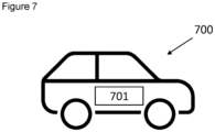
- Figure 7 shows an example automotive vehicle 700 which comprises the MIMO radar system 701 as previously disclosed. While figure 7 depicts a car 700, it will be appreciated that the vehicle may be any automotive vehicle which can benefit from an installed radar system.
- the automotive vehicle may be a car, a van, a lorry, a bus, a construction vehicle or any other vehicle which may share a road with other vehicles are traversing.
- the MIMO radar system may further be used in vehicles which do not use roads but that might have other obstacles that need to be navigated, such as boats or ships.
- the set of instructions/method steps described above are implemented as functional and software instructions embodied as a set of executable instructions which are effected on a computer or machine which is programmed with and controlled by said executable instructions. Such instructions are loaded for execution on a processor (such as one or more CPUs).
- processor includes microprocessors, microcontrollers, processor modules or subsystems (including one or more microprocessors or microcontrollers), or other control or computing devices.
- a processor can refer to a single component or to plural components.
- the set of instructions/methods illustrated herein and data and instructions associated therewith are stored in respective storage devices, which are implemented as one or more non-transient machine or computer-readable or computer-usable storage media or mediums.
- Such computer-readable or computer usable storage medium or media is (are) considered to be part of an article (or article of manufacture).
- An article or article of manufacture can refer to any manufactured single component or multiple components.
- the non-transient machine or computer usable media or mediums as defined herein excludes signals, but such media or mediums may be capable of receiving and processing information from signals and/or other transient mediums.
- Example embodiments of the material discussed in this specification can be implemented in whole or in part through network, computer, or data based devices and/or services. These may include cloud, internet, intranet, mobile, desktop, processor, look-up table, microcontroller, consumer equipment, infrastructure, or other enabling devices and services. As may be used herein and in the claims, the following non-exclusive definitions are provided.
- one or more instructions or steps discussed herein are automated.
- the terms automated or automatically mean controlled operation of an apparatus, system, and/or process using computers and/or mechanical/electrical devices without the necessity of human intervention, observation, effort and/or decision. It will be appreciated that any components said to be coupled may be coupled or connected either directly or indirectly. In the case of indirect coupling, additional components may be located between the two components that are said to be coupled.
Landscapes
- Engineering & Computer Science (AREA)
- Radar, Positioning & Navigation (AREA)
- Remote Sensing (AREA)
- Physics & Mathematics (AREA)
- Computer Networks & Wireless Communication (AREA)
- General Physics & Mathematics (AREA)
- Electromagnetism (AREA)
- Ocean & Marine Engineering (AREA)
- Radar Systems Or Details Thereof (AREA)
Priority Applications (3)
| Application Number | Priority Date | Filing Date | Title |
|---|---|---|---|
| EP23307158.8A EP4567450B1 (fr) | 2023-12-08 | 2023-12-08 | Système radar à entrées multiples et sorties multiples |
| US18/961,997 US20250189628A1 (en) | 2023-12-08 | 2024-11-27 | Multiple input multiple output radar system |
| CN202411788619.3A CN120122058A (zh) | 2023-12-08 | 2024-12-06 | 多输入多输出雷达系统 |
Applications Claiming Priority (1)
| Application Number | Priority Date | Filing Date | Title |
|---|---|---|---|
| EP23307158.8A EP4567450B1 (fr) | 2023-12-08 | 2023-12-08 | Système radar à entrées multiples et sorties multiples |
Publications (2)
| Publication Number | Publication Date |
|---|---|
| EP4567450A1 true EP4567450A1 (fr) | 2025-06-11 |
| EP4567450B1 EP4567450B1 (fr) | 2026-04-22 |
Family
ID=89386300
Family Applications (1)
| Application Number | Title | Priority Date | Filing Date |
|---|---|---|---|
| EP23307158.8A Active EP4567450B1 (fr) | 2023-12-08 | 2023-12-08 | Système radar à entrées multiples et sorties multiples |
Country Status (3)
| Country | Link |
|---|---|
| US (1) | US20250189628A1 (fr) |
| EP (1) | EP4567450B1 (fr) |
| CN (1) | CN120122058A (fr) |
Citations (2)
| Publication number | Priority date | Publication date | Assignee | Title |
|---|---|---|---|---|
| US20200233076A1 (en) * | 2019-06-27 | 2020-07-23 | Intel Corporation | Methods and apparatus to implement compact time-frequency division multiplexing for mimo radar |
| US11614531B2 (en) * | 2020-12-02 | 2023-03-28 | Nxp Usa, Inc. | Co-prime coded (CPC) doppler division multiplexing (DDM) MIMO radar method and system |
-
2023
- 2023-12-08 EP EP23307158.8A patent/EP4567450B1/fr active Active
-
2024
- 2024-11-27 US US18/961,997 patent/US20250189628A1/en active Pending
- 2024-12-06 CN CN202411788619.3A patent/CN120122058A/zh active Pending
Patent Citations (2)
| Publication number | Priority date | Publication date | Assignee | Title |
|---|---|---|---|---|
| US20200233076A1 (en) * | 2019-06-27 | 2020-07-23 | Intel Corporation | Methods and apparatus to implement compact time-frequency division multiplexing for mimo radar |
| US11614531B2 (en) * | 2020-12-02 | 2023-03-28 | Nxp Usa, Inc. | Co-prime coded (CPC) doppler division multiplexing (DDM) MIMO radar method and system |
Non-Patent Citations (2)
| Title |
|---|
| DANIEL J RABIDEAU: "Doppler-offset waveforms for MIMO radar", RADAR CONFERENCE (RADAR), 2011 IEEE, IEEE, 23 May 2011 (2011-05-23), pages 965 - 970, XP031902243, ISBN: 978-1-4244-8901-5, DOI: 10.1109/RADAR.2011.5960679 * |
| VAN ROSSUM WIM ET AL: "Doppler ambiguity resolution using random slow-time code division multiple access MIMO radar with sparse signal processing", 2018 IEEE RADAR CONFERENCE (RADARCONF18), IEEE, 23 April 2018 (2018-04-23), pages 441 - 446, XP033356246, DOI: 10.1109/RADAR.2018.8378599 * |
Also Published As
| Publication number | Publication date |
|---|---|
| EP4567450B1 (fr) | 2026-04-22 |
| US20250189628A1 (en) | 2025-06-12 |
| CN120122058A (zh) | 2025-06-10 |
Similar Documents
| Publication | Publication Date | Title |
|---|---|---|
| US20230273292A1 (en) | Method and apparatus for radar waveforms using orthogonal sequence sets | |
| US11662427B2 (en) | Method and system for frequency offset modulation range division MIMO automotive radar | |
| US11360204B2 (en) | Ambiguity resolution for a MIMO radar system | |
| CN110824444B (zh) | 用于解析速度模糊的mimo雷达译码 | |
| CN109932722B (zh) | 用于消除干扰信号的设备和方法 | |
| US11762077B2 (en) | Method and system for frequency offset modulation range division MIMO automotive radar using I-channel only modulation mixer | |
| US10754008B2 (en) | Vehicle radar system that addresses doppler frequency shift and method of using the same | |
| US10142133B2 (en) | Successive signal interference mitigation | |
| CN113466867B (zh) | 抑制干扰的方法和探测装置 | |
| US20170023670A1 (en) | Radar system | |
| US20190018127A1 (en) | Radar system | |
| US20240402324A1 (en) | Mimo radar apparatus and mimo radar method | |
| US12578425B2 (en) | MIMO radar apparatus and MIMO radar method | |
| US11632281B1 (en) | System and method for joint radar-sensing and communication waveform utilizing unique word OFDM (UW-OFDM) | |
| US20230296749A1 (en) | Phase-coded frequency modulated continuous wave (fmcw) radar system method and architecture | |
| WO2022027320A1 (fr) | Procédé et dispositif d'émission sur la base d'un signal radar | |
| EP4567450B1 (fr) | Système radar à entrées multiples et sorties multiples | |
| Artyukhin et al. | Development of effective anti-interference primary signal processing for mmWave automotive radar | |
| EP4538733A1 (fr) | Système et procédé radar à entrées multiples sorties multiples (mimo) à multiplexage par répartition doppler (rtdm) hybride à multiplexage par répartition aléatoire (ddm) | |
| EP4394435A1 (fr) | Compensation de décalage temporel dans un radar distribué cohérent | |
| EP4170377A1 (fr) | Appareil radar et procédé avec contenu incorporé dans le signal radar | |
| US20250258272A1 (en) | Radar system and method with interference suppression | |
| US20250155552A1 (en) | MIMO Radar Apparatus | |
| CN120161416A (zh) | Mimo雷达发射和信号处理 | |
| CN117538855A (zh) | 目标检测方法、装置、雷达及介质 |
Legal Events
| Date | Code | Title | Description |
|---|---|---|---|
| PUAI | Public reference made under article 153(3) epc to a published international application that has entered the european phase |
Free format text: ORIGINAL CODE: 0009012 |
|
| STAA | Information on the status of an ep patent application or granted ep patent |
Free format text: STATUS: THE APPLICATION HAS BEEN PUBLISHED |
|
| AK | Designated contracting states |
Kind code of ref document: A1 Designated state(s): AL AT BE BG CH CY CZ DE DK EE ES FI FR GB GR HR HU IE IS IT LI LT LU LV MC ME MK MT NL NO PL PT RO RS SE SI SK SM TR |
|
| STAA | Information on the status of an ep patent application or granted ep patent |
Free format text: STATUS: REQUEST FOR EXAMINATION WAS MADE |
|
| GRAP | Despatch of communication of intention to grant a patent |
Free format text: ORIGINAL CODE: EPIDOSNIGR1 |
|
| STAA | Information on the status of an ep patent application or granted ep patent |
Free format text: STATUS: GRANT OF PATENT IS INTENDED |
|
| 17P | Request for examination filed |
Effective date: 20251211 |
|
| INTG | Intention to grant announced |
Effective date: 20260121 |
|
| GRAS | Grant fee paid |
Free format text: ORIGINAL CODE: EPIDOSNIGR3 |
|
| GRAA | (expected) grant |
Free format text: ORIGINAL CODE: 0009210 |
|
| STAA | Information on the status of an ep patent application or granted ep patent |
Free format text: STATUS: THE PATENT HAS BEEN GRANTED |
|
| AK | Designated contracting states |
Kind code of ref document: B1 Designated state(s): AL AT BE BG CH CY CZ DE DK EE ES FI FR GB GR HR HU IE IS IT LI LT LU LV MC ME MK MT NL NO PL PT RO RS SE SI SK SM TR |
|
| REG | Reference to a national code |
Ref country code: CH Ref legal event code: F10 Free format text: ST27 STATUS EVENT CODE: U-0-0-F10-F00 (AS PROVIDED BY THE NATIONAL OFFICE) Effective date: 20260422 Ref country code: GB Ref legal event code: FG4D |