EP4567461A1 - Näherungserfassungsvorrichtung - Google Patents
Näherungserfassungsvorrichtung Download PDFInfo
- Publication number
- EP4567461A1 EP4567461A1 EP24215194.2A EP24215194A EP4567461A1 EP 4567461 A1 EP4567461 A1 EP 4567461A1 EP 24215194 A EP24215194 A EP 24215194A EP 4567461 A1 EP4567461 A1 EP 4567461A1
- Authority
- EP
- European Patent Office
- Prior art keywords
- state
- signal
- output signal
- value
- proximity sensor
- Prior art date
- Legal status (The legal status is an assumption and is not a legal conclusion. Google has not performed a legal analysis and makes no representation as to the accuracy of the status listed.)
- Pending
Links
Images


Classifications
-
- G—PHYSICS
- G01—MEASURING; TESTING
- G01S—RADIO DIRECTION-FINDING; RADIO NAVIGATION; DETERMINING DISTANCE OR VELOCITY BY USE OF RADIO WAVES; LOCATING OR PRESENCE-DETECTING BY USE OF THE REFLECTION OR RERADIATION OF RADIO WAVES; ANALOGOUS ARRANGEMENTS USING OTHER WAVES
- G01S7/00—Details of systems according to groups G01S13/00, G01S15/00, G01S17/00
- G01S7/48—Details of systems according to groups G01S13/00, G01S15/00, G01S17/00 of systems according to group G01S17/00
- G01S7/497—Means for monitoring or calibrating
-
- G—PHYSICS
- G01—MEASURING; TESTING
- G01S—RADIO DIRECTION-FINDING; RADIO NAVIGATION; DETERMINING DISTANCE OR VELOCITY BY USE OF RADIO WAVES; LOCATING OR PRESENCE-DETECTING BY USE OF THE REFLECTION OR RERADIATION OF RADIO WAVES; ANALOGOUS ARRANGEMENTS USING OTHER WAVES
- G01S7/00—Details of systems according to groups G01S13/00, G01S15/00, G01S17/00
- G01S7/48—Details of systems according to groups G01S13/00, G01S15/00, G01S17/00 of systems according to group G01S17/00
- G01S7/483—Details of pulse systems
- G01S7/486—Receivers
- G01S7/487—Extracting wanted echo signals, e.g. pulse detection
- G01S7/4873—Extracting wanted echo signals, e.g. pulse detection by deriving and controlling a threshold value
-
- G—PHYSICS
- G01—MEASURING; TESTING
- G01S—RADIO DIRECTION-FINDING; RADIO NAVIGATION; DETERMINING DISTANCE OR VELOCITY BY USE OF RADIO WAVES; LOCATING OR PRESENCE-DETECTING BY USE OF THE REFLECTION OR RERADIATION OF RADIO WAVES; ANALOGOUS ARRANGEMENTS USING OTHER WAVES
- G01S17/00—Systems using the reflection or reradiation of electromagnetic waves other than radio waves, e.g. lidar systems
- G01S17/02—Systems using the reflection of electromagnetic waves other than radio waves
- G01S17/04—Systems determining the presence of a target
-
- G—PHYSICS
- G01—MEASURING; TESTING
- G01S—RADIO DIRECTION-FINDING; RADIO NAVIGATION; DETERMINING DISTANCE OR VELOCITY BY USE OF RADIO WAVES; LOCATING OR PRESENCE-DETECTING BY USE OF THE REFLECTION OR RERADIATION OF RADIO WAVES; ANALOGOUS ARRANGEMENTS USING OTHER WAVES
- G01S17/00—Systems using the reflection or reradiation of electromagnetic waves other than radio waves, e.g. lidar systems
- G01S17/02—Systems using the reflection of electromagnetic waves other than radio waves
- G01S17/06—Systems determining position data of a target
- G01S17/08—Systems determining position data of a target for measuring distance only
- G01S17/10—Systems determining position data of a target for measuring distance only using transmission of interrupted, pulse-modulated waves
-
- G—PHYSICS
- G01—MEASURING; TESTING
- G01S—RADIO DIRECTION-FINDING; RADIO NAVIGATION; DETERMINING DISTANCE OR VELOCITY BY USE OF RADIO WAVES; LOCATING OR PRESENCE-DETECTING BY USE OF THE REFLECTION OR RERADIATION OF RADIO WAVES; ANALOGOUS ARRANGEMENTS USING OTHER WAVES
- G01S7/00—Details of systems according to groups G01S13/00, G01S15/00, G01S17/00
- G01S7/48—Details of systems according to groups G01S13/00, G01S15/00, G01S17/00 of systems according to group G01S17/00
- G01S7/481—Constructional features, e.g. arrangements of optical elements
- G01S7/4811—Constructional features, e.g. arrangements of optical elements common to transmitter and receiver
- G01S7/4813—Housing arrangements
-
- G—PHYSICS
- G01—MEASURING; TESTING
- G01S—RADIO DIRECTION-FINDING; RADIO NAVIGATION; DETERMINING DISTANCE OR VELOCITY BY USE OF RADIO WAVES; LOCATING OR PRESENCE-DETECTING BY USE OF THE REFLECTION OR RERADIATION OF RADIO WAVES; ANALOGOUS ARRANGEMENTS USING OTHER WAVES
- G01S7/00—Details of systems according to groups G01S13/00, G01S15/00, G01S17/00
- G01S7/48—Details of systems according to groups G01S13/00, G01S15/00, G01S17/00 of systems according to group G01S17/00
- G01S7/481—Constructional features, e.g. arrangements of optical elements
- G01S7/4814—Constructional features, e.g. arrangements of optical elements of transmitters alone
-
- G—PHYSICS
- G01—MEASURING; TESTING
- G01S—RADIO DIRECTION-FINDING; RADIO NAVIGATION; DETERMINING DISTANCE OR VELOCITY BY USE OF RADIO WAVES; LOCATING OR PRESENCE-DETECTING BY USE OF THE REFLECTION OR RERADIATION OF RADIO WAVES; ANALOGOUS ARRANGEMENTS USING OTHER WAVES
- G01S7/00—Details of systems according to groups G01S13/00, G01S15/00, G01S17/00
- G01S7/48—Details of systems according to groups G01S13/00, G01S15/00, G01S17/00 of systems according to group G01S17/00
- G01S7/481—Constructional features, e.g. arrangements of optical elements
- G01S7/4816—Constructional features, e.g. arrangements of optical elements of receivers alone
-
- G—PHYSICS
- G01—MEASURING; TESTING
- G01S—RADIO DIRECTION-FINDING; RADIO NAVIGATION; DETERMINING DISTANCE OR VELOCITY BY USE OF RADIO WAVES; LOCATING OR PRESENCE-DETECTING BY USE OF THE REFLECTION OR RERADIATION OF RADIO WAVES; ANALOGOUS ARRANGEMENTS USING OTHER WAVES
- G01S7/00—Details of systems according to groups G01S13/00, G01S15/00, G01S17/00
- G01S7/48—Details of systems according to groups G01S13/00, G01S15/00, G01S17/00 of systems according to group G01S17/00
- G01S7/483—Details of pulse systems
- G01S7/486—Receivers
- G01S7/4865—Time delay measurement, e.g. time-of-flight measurement, time of arrival measurement or determining the exact position of a peak
-
- G—PHYSICS
- G01—MEASURING; TESTING
- G01S—RADIO DIRECTION-FINDING; RADIO NAVIGATION; DETERMINING DISTANCE OR VELOCITY BY USE OF RADIO WAVES; LOCATING OR PRESENCE-DETECTING BY USE OF THE REFLECTION OR RERADIATION OF RADIO WAVES; ANALOGOUS ARRANGEMENTS USING OTHER WAVES
- G01S7/00—Details of systems according to groups G01S13/00, G01S15/00, G01S17/00
- G01S7/48—Details of systems according to groups G01S13/00, G01S15/00, G01S17/00 of systems according to group G01S17/00
- G01S7/51—Display arrangements
Definitions
- This description relates generally to electronic devices, more particularly to electronic devices comprising a proximity sensor, for example a proximity sensor arranged under a display screen.
- the proximity sensor may be of the time-of-flight (ToF) type, and in this case, the processing unit may be configured to calculate the travel time between the emission of the light beam and its reception by the detector, the distance between the object and the proximity sensor then being able to be deduced on the basis of this travel time.
- ToF time-of-flight
- Electronic devices include a proximity sensor positioned beneath a screen, for example a display screen.
- the display screen may be an organic light-emitting diode (OLED) screen.
- OLED organic light-emitting diode
- a proximity sensor beneath the display screen of a smartphone may detect the presence of a user against the screen, for example when the user presses an ear to the screen to make a phone call, which may cause the screen to turn off.
- the proximity sensor may detect if the user moves away from the screen in order to turn the screen back on.
- the proximity sensor may fail to distinguish whether the object is at a very short distance (very close object), typically a few millimeters, for example less than 2 or 3 millimeters, or at a long distance (far object), typically more than a few centimeters, for example more than 20, 30 or even 40 millimeters, from said sensor.
- very close object typically a few millimeters, for example less than 2 or 3 millimeters
- far object typically more than a few centimeters, for example more than 20, 30 or even 40 millimeters
- an electronic device comprising at least one display screen and a proximity sensor under the display screen, more generally under a wall with low light transmittance, capable of determining whether an object is at very short or long distance.
- a proximity capture device i.e. a device comprising a proximity sensor, capable of determining whether an object is at very short or long distance with a simple solution to implement.
- One embodiment overcomes all or part of the drawbacks of known proximity sensors.
- the third state corresponds to a first distance between the object and the proximity sensor
- the fourth state corresponds to a second distance between the object and the proximity sensor, the second distance being greater than the first distance, or the first distance being greater than the second distance.
- the output signal is obtained by subtracting the other of the first and second signals to the signal weighted by the weighting coefficient.
- one of the first and second signals is weighted by the weighting coefficient, forming the signal weighted by the weighting coefficient, the other of the first and second signals is not weighted by the weighting coefficient and is subtracted from the signal weighted by the weighting coefficient.
- the output signal is preprocessed by a processing device of the proximity sensor, the processing device being connected to the control circuit.
- the light emitter and the light detector are positioned under a covering wall of the proximity sensor.
- the first and second photodiodes are arranged next to each other, and spaced apart by a distance, in a direction substantially parallel to the plane of the covering wall.
- the covering wall comprises a first opening in line with the light emitter, and a second opening in line with the light detector, for example the second opening is centered with the first photodiode, the second photodiode being positioned substantially under an unopened portion of the covering wall.
- the first photodiode is positioned between the light emitter and the second photodiode.
- the proximity sensor is under a wall capable of generating a crosstalk phenomenon by reflection on said wall of light signals emitted by the light emitter then transmitted to the detector.
- the wall has a light transmission coefficient of less than 5% at the working wavelengths of the proximity sensor.
- control circuit is adapted to generate a state signal, the state signal comprising a first value in the third state and a second value in the fourth state.
- the wall is a display screen, for example an OLED type display screen
- the status signal is adapted to be transmitted to the display screen, or a control circuit of said display screen, so as to control its switching off, or its switching on, depending on whether the status signal takes the first value or the second value.
- control circuit generates a state signal, the state signal comprising a first value in the third state and a second value in the fourth state.
- the wall is a display screen, for example an OLED type display screen, and the status signal is transmitted to the display screen, or a control circuit for said display screen, so as to control its switching off or on, depending on whether the status signal takes the first value or the second value.
- the second value is selected to make the output signal asymmetric between a short distance and a long distance, to be able to determine whether the object is a short or long distance from the proximity sensor.
- the expressions "about”, “approximately”, “substantially”, and “of the order of” mean to within 10%, preferably to within 5%.
- the luminous transmittance, or transmission coefficient, of an element is defined as the fraction of the light intensity passing through this element.
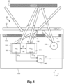
- FIG. 1 represents a proximity sensor 100 included in an electronic device 10 and positioned under a display screen 12 (DISPLAY) of the electronic device, and illustrates a mode of operation of such a sensor.
- DISPLAY display screen 12
- a proximity sensor 100 comprises a light emitter 110 (TX) and a light detector 120 (RX) located under a covering wall 130, for example a cover (CAP), which may correspond to an upper wall of a housing containing the emitter and the detector.
- TX light emitter 110
- RX light detector 120
- CAP cover
- the emitter 110 may comprise a light-emitting diode (LED) or a vertical cavity surface emitting laser (VCSEL).
- LED light-emitting diode
- VCSEL vertical cavity surface emitting laser
- the detector 120 shown comprises two photodiodes, a first photodiode 121 (PD N , NEAR) and a second photodiode 122 (PD F , FAR).
- the two photodiodes 121, 122 are positioned such that the first photodiode 121 is closer to the emitter 110 than the second photodiode 122.
- the first photodiode 121 is positioned between the emitter 110 and the second photodiode 122.
- the wall 130 comprises two openings 131, 132, a first opening 131 in line with the emitter 110 and a second opening 132 in line with the detector 120, for example more particularly centered with the first photodiode 121, the second photodiode 122 being positioned substantially under a non-open portion of the wall 130.
- the two photodiodes 121, 122 are arranged next to each other, and spaced apart by a first distance d1, in a direction X substantially parallel to the plane of the wall 130.
- the first photodiode 121 may be adapted to detect more particularly a close object, while the second photodiode 122 may be adapted to detect more particularly a distant object.
- the electronic device 10 shown comprises a display screen 12, the proximity sensor 100 being arranged under this display screen.
- the display screen may be an organic light-emitting diode (OLED) type screen.
- OLED organic light-emitting diode
- the wall 130 is positioned between the emitter/detector and the display screen 12, and the display screen 12 is positioned between the proximity sensor 100 and the object 20.
- the output signal DN may have a value, for example an amplitude, a digital signal, for example a number of pulses or counts, which varies according to the distance separating the object 20 and the detector 120, and the processing device 140 may process this signal, for example count the pulses, to deduce therefrom the presence or absence of an object near a proximity sensor.
- a digital signal for example a number of pulses or counts, which varies according to the distance separating the object 20 and the detector 120
- the processing device 140 may process this signal, for example count the pulses, to deduce therefrom the presence or absence of an object near a proximity sensor.
- the output signal DN of the proximity sensor 100 may be transmitted to the display screen 12 (DISPLAY), or to a control circuit of the display screen, in order to turn off (DISPLAY OFF) or turn on (DISPLAY ON) the display screen.
- the display screen 12 may be a display screen of a mobile phone such as a smartphone, and include the proximity sensor 100 under the display screen 12, and the object 20 may be an organ, for example an ear, of a user of the mobile phone.
- the DN output signal value goes above a detection threshold (DETECT) when the object approaches the proximity sensor, this can trigger the display to turn off (DISPLAY OFF), as shown in Figure 2A
- the screen can remain off as long as the output signal value remains above a release threshold (RELEASE).
- the threshold RELEASE unlocking threshold is lower than the DECTECT detection threshold, as shown in Figure 2B , to ensure hysteresis, and for example to support different tolerances, such as electrical, optical and/or mechanical tolerances (sensor assembly, integration behind the display).
- the gap between the detection threshold and the release threshold can be set to achieve stable hysteresis-type operation. If the value of the output signal DN falls below the release threshold RELEASE when the object moves away from the proximity sensor, this can trigger the display to turn on (DISPLAY ON), as shown in Figure 2B .
- a mode of operation of the proximity sensor 100 is explained.
- the transmitter 110 emits a light signal S through the first opening 131 and the screen 12.
- the light signal can be reflected by an object 20 and the reflected light signal can be picked up in return by the detector 120 through the screen 12 and the second opening 132.
- a first reflected light signal S N can be detected by the first photodiode 121, and a second reflected light signal S F can be detected by the first photodiode 122.
- the first photodiode 121 detects a first signal A N from the ambient light (first ambient light signal), and the second photodiode 122 detects a second signal A F from the ambient light (second ambient light signal).
- an LED type display screen and more generally of a screen, or a wall, with low light transmittance, typically with a transmittance of less than 5% at wavelengths of work of the sensor, generated a phenomenon of crosstalk, consisting of the transmission of light beams between the transmitter and the detector by optical reflection on the screen.
- the first photodiode 121 can detect a first crosstalk signal XT N
- the second photodiode 122 can detect a second crosstalk signal XT F .
- the crosstalk phenomenon can have the disadvantage of degrading the performance of the proximity sensor, due to an unwanted optical component (noise) caused by light signals that are not emitted by the object, in addition to the useful optical reflection component caused by the reflection of the emitted light signal on the object.
- the ambient light component for each photodiode can be compensated, for example in the processing device 140, by acquiring measurements with the emitter off, since then only the ambient light is detected, then measurements with the emitter on, and by performing a subtraction between the signal generated with the emitter on and the signal generated with the emitter off, for each photodiode. This can be achieved by performing the acquisition of several measurement samples in each configuration (emitter off and emitter on).
- the proximity sensor 100 for example the processing device 140, may, based on the signals generated by the photodiodes 121, 122, not distinguish whether the object is at very short distance, typically a few millimeters, or at long distance, typically more than a few centimeters, as illustrated in the Figure 3 .
- FIG. 3 represents curves of evolution of signals generated by the photodiodes of the proximity sensor 100 of the Figure 1 depending on the distance (in mm) between the proximity sensor and an object, and for two different quantities of measurement samples.
- the generated signals are, for example, in the form of counts.
- the right curves 311, 312 correspond to the signals generated by the first photodiode 121 (NEAR), while the left curves 321, 322 correspond to the signals generated by the second photodiode 122 (FAR).
- the upper curves 312, 322 correspond to 30 measurement samples, and the lower curves 311, 321 correspond to 6 measurement samples. It can be seen that the level of each signal, whether for the first photodiode 121 or the second photodiode 122, is substantially the same whether the distance is less than 2 or 3 millimeters (very short distance) or greater than 30 or 40 millimeters (long distance), and that the number of samples does not change anything.
- One solution may be to apply a ratio between the first signal DN N and the second signal DN F , or between the second signal DN F and the first signal DN N .
- Another solution may be to weight the first signal DN N by a coefficient ⁇ before subtracting the second signal DN F from it, or to weight the second signal DN F by the coefficient ⁇ before subtracting the first signal DN N and to test several values of the coefficient ⁇ to minimize the crosstalk components in the signals, or even eliminate them.
- the photodiodes and/or the positioning of the object there may be more reflected signal detected on the NEAR photodiode than on the FAR photodiode, such that ⁇ is less than 1, or conversely there may be more reflected signal detected on the FAR photodiode than on the NEAR photodiode, such that ⁇ is greater than 1.
- ⁇ coefficient in the compensation equation By varying the ⁇ coefficient in the compensation equation, for example by applying several values to the ⁇ coefficient, one can obtain a DN output signal with mainly the useful optical reflection component, i.e. a DN output signal stripped of crosstalk components, or at least with reduced crosstalk components. For example, at least four, or even at least eight, values of the ⁇ coefficient are required.
- these solutions require performing numerous calculations that require implementing logic circuits, which have a significant surface footprint on the electronic device, and which consume electrical energy.
- these solutions may require having a minimum distance d1 between the two photodiodes in order to guarantee different behavior of the signals between the two NEAR and FAR photodiodes. Indeed, the greater the difference in the behavior of the two NEAR and FAR photodiodes, the better the detection.
- the distance d1 is greater than 0.5 mm, or even greater than 1 mm, for example equal to approximately 1.2 mm, which may result in further increasing the size of the electronic device.
- the inventors propose a proximity capture device, that is to say a device comprising a proximity sensor, which makes it possible to overcome all or part of the drawbacks described above, in particular to respond to the problem of discrimination between a very close object or a distant object, and this, preferably with a simple solution to implement, for example, a solution which makes it possible to avoid increasing the size of the proximity capture device and which consumes little electrical energy.
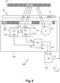
- FIG. 4 represents a proximity capture device 400 according to one embodiment, included in an electronic device 40 and positioned under a wall 12 (DISPLAY) of the electronic device 40.
- the proximity capture device 400 includes a proximity sensor that may be similar to the proximity sensor 100 of the Figure 1 , which comprises a light emitter 110 and a light detector 120 including a first photodiode 121 (NEAR) and a second photodiode 122 (FAR) under a covering wall 130, such as a hood (CAP).
- the photodiodes are arranged next to each other, and spaced apart by a second distance d2, in a direction X substantially parallel to the plane of the wall 130, but other configurations are possible.
- the wall 130 comprises two openings 131, 132, a first opening 131 in line with the emitter 110 and a second opening 132 in line with the detector 120, for example more particularly centered with the first photodiode 121, the second photodiode 122 being positioned substantially under an unopened portion of the wall 130.
- Each photodiode is adapted to detect a light signal S emitted by the emitter 110, then reflected S N , S F by an object 20 (TARGET). By detecting the reflected light signal, and generally parasitic signals as described further above, each photodiode is adapted to generate a signal DN N , DN F .
- the proximity sensor 100 may also comprise, similarly to the proximity sensor of the Figure 1 , a processing device 140 (SPU) configured to process the signals generated by the detector 120, in the example shown the signals DN N , DN F generated by the two photodiodes 121, 122, for a proximity detection calculation.
- the processing device 140 can generate an output signal DN, a function of the signals DN N , DN F .
- the proximity sensor 100 may be of the time of flight (ToF) sensor type, and in this case, the processing device 140 may be configured to calculate the travel time between the emission of the light signal and its reception by the detector, the distance between the object and the proximity sensor then being able to be deduced on the basis of this travel time.
- ToF time of flight
- the proximity sensor 100 may operate with infrared (IR) or near infrared (NIR) light.
- IR infrared
- NIR near infrared
- the proximity sensor 100 may operate at wavelengths in a non-visible spectrum, for example, wavelengths greater than 850 nm.
- the wall 12 may be a wall with low light transmittance, more broadly a wall capable of generating a crosstalk phenomenon at the working wavelengths of the proximity sensor 100, by reflection on said screen of the light signals emitted by the light emitter 110 and transmitted to the light detector 120.
- the wall 12 may be a display screen, for example an OLED type display screen, a screen bezel which is an area without a display in a border region of a display screen, or dark cover glass.
- the proximity capture device 400 further comprises a control circuit 410 (SM), for example implemented by a state machine, or by a processor (CPU, central processing unit).
- SM control circuit 410
- CPU central processing unit
- the control circuit 410 is adapted to receive a signal from the detector 120.
- the control circuit 410 can be connected to the detector 120 via the processing device 140, which can preprocess the signals DN N , DN F acquired by the two photodiodes, so that the control circuit 410 is adapted to recover the output signal DN.
- the output signal DN is preferably obtained by weighting one of the first and second signals by the weighting coefficient ⁇ , for example by weighting the first signal DN N of the first photodiode 121 by the coefficient ⁇ before subtracting from it the second signal DN F of the second photodiode 122, or by weighting the second signal DN F by the weighting coefficient ⁇ before subtracting from it the first signal DN N .
- the control circuit can be of the coprocessor type.
- the control circuit 410 has been shown as not being part of the proximity sensor 100, but as being part of the proximity capture device 400 and being connected to the proximity sensor 100. This is not limiting and other configurations are possible. According to In a variant, the control circuit 410 may be included in the proximity sensor 100, for example in the processing device 140. According to another variant, the control circuit 410 may recover the data from the proximity sensor 100 without necessarily being connected to this sensor, and the recovered data may be post-processed in the control circuit 410.
- processing device 140 can be omitted in the proximity sensor of the Figure 3 , and the signals generated by the two photodiodes can be directed directly to the control circuit 410 without having been preprocessed.
- control circuit 410 sends to the processing device 140 a control signal S ⁇ to modify the coefficient ⁇ , so as to modify the output signal DN.
- the control circuit transitions from the second state to a third state, and if the output signal DN is greater than or equal to the second threshold, then the control circuit transitions from the second state to a fourth state.
- the control circuit 410 provides a status signal ST which is a function of the result of the comparison between the output signal and the second threshold, for example depending on whether the control circuit 410 is in the third state or the fourth state.
- the ST status signal can be an analog or digital signal, a value in a readable status register, or both.
- the ST status signal can also be a variable in a program that executes the state machine.
- the status signal ST may comprise a first value ST N corresponding to an object at a first distance from the proximity sensor, and a second value ST F corresponding to an object at a second distance from the proximity sensor, the second distance being greater than the first distance.
- the first distance may be a very short distance (very close object), typically a few millimeters, for example less than 2 or 3 millimeters.
- the second distance may be a long distance (far object), typically more than a few centimeters, for example more than 20, 30 millimeters, or even more than 40 millimeters.
- the status signal ST can be transmitted to the display screen 12, or a control circuit of the display screen, for example in order to control its switching off, or its maintenance in off mode, if the status signal ST takes the first value ST N , or its switching on, or its maintenance in on mode, if the status signal ST takes the second value ST F .
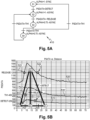
- FIG. 5A represents an exemplary embodiment of the control circuit 410 of the proximity capture device 400 of the Figure 4 .
- the control circuit of the Figure 5A is implemented by a state machine.
- the Figure 5B illustrates an example of operation of the control circuit 410 of the Figure 5A .
- Figures 5A and 5B is described in relation to the application of the Figures 2A and 2B , and can have several applications related to proximity detection under a screen or a low transmittance wall, for example in products such as smartphones, computers, tablets, headsets, virtual reality headsets, etc.
- a four-state state machine has been represented, but the state machine could have more than four states.
- the proximity sensor can synchronize with a screen clock, for example to match the times when the light emitter emits the light signal with the screen activity. This is why we can speak of synchronous mode (SYNC).
- SYNC synchronous mode
- ASYNC asynchronous mode
- the first value ⁇ 1 is equal to 1 and the second value ⁇ 2 is equal to 0.75, but other values may be suitable.
- the states, transitions and thresholds are represented in relation to curves of evolution of the output signal of the proximity sensor as a function of the distance between the object and the proximity sensor (in millimeters).
- the first curve 510 corresponds to an evolution of the PSDATA output signal when the weighting coefficient has the first value ⁇ 1 and the screen is on (first configuration).
- the second curve 520 corresponds to an evolution of the PSDATA output signal when the weighting coefficient has the first value ⁇ 1 and the screen is off: in this second configuration, the number of measurement samples can be higher than in the first configuration, for example to increase the signal-to-noise ratio, which explains why the RELEASE threshold is above the DETECT threshold in the example shown.
- the third curve 530 corresponds to an evolution of the PSDATA output signal when the weighting coefficient has the second value ⁇ 2 and the screen is off (third configuration).
- the output signal of the proximity sensor follows the first curve 510.
- the PSDATA output signal exceeds the DETECT detection threshold. The screen then turns off, and we go to state S2.
- state S2 the output signal of the proximity sensor follows the second curve 520, while the screen is off.
- the screen could turn back on as desired while the distance between the object and the sensor increases, but it could also turn back on while the distance between the object and the sensor decreases further, which is not desired.
- the output signal of the proximity sensor does not allow us to know whether the object is moving away from the sensor or if it is getting closer to it.
- the weighting coefficient takes a second value ⁇ 2 different from the first value, so that the output signal PSDATA is modified.
- This second value ⁇ 2 is preferably chosen so as to make the output signal asymmetrical between a short distance and a long distance, and to be able to determine whether the object is at a short or long distance from the sensor.
- the output signal PSDATA then follows the third curve 530. In the example shown, if the output signal PSDATA is below the threshold TH1 (below the point 531), then we move to state S4, and the screen can remain off, and if the output signal PSDATA is above the threshold TH1, then we move to state S1 and the screen can be turned back on.
- the threshold TH1 is between the thresholds DETECT and RELEASE, but this is not limiting.
- the embodiments make it possible to respond to the problem of discrimination between a very close object or a distant object, with a simple solution to implement, for example a state machine with four states, three thresholds (two could be sufficient if we start from state S2), and two values of a weighting coefficient, and preferably with a displacement of the object or the proximity sensor.
- a simple solution to implement, for example a state machine with four states, three thresholds (two could be sufficient if we start from state S2), and two values of a weighting coefficient, and preferably with a displacement of the object or the proximity sensor.
- Such a solution can make it possible to respond to a constraint of limiting the size of a proximity capture device, and of limiting the consumption of electrical energy.
- FIG. 6 represents a curve of the evolution of the output signal of the proximity sensor 100 of the Figure 4 , and the different states of the control circuit 410 of the Figure 5A depending on the distance between the proximity sensor and an object.
- the 610 curve in the upper part of the Figure 6 represents the distance between the object and the proximity sensor (Distance).
- the 620 curve in the middle part of the Figure 6 represents the evolution curve of the output signal (PSDATA) of the proximity sensor 100.
- the lines 630 in the lower part of the Figure 6 represent the different states of the control circuit 410. These lines correspond to several values of each state S1-S4, which explains the line shape and not the single point shape.
- FIG. 6 shows that when the output signal PSDATA is below the detection threshold DETECT, the control circuit is in the fourth state S1, then when the output signal PSDATA goes above the detection threshold DETECT, the control circuit goes into the first state S2.
- the output signal PSDATA also passes above the RELEASE unlocking threshold.
- the control circuit enters the second state S3, in which the weighting coefficient passes from the first value ⁇ 1 to the second value ⁇ 2.
- the control circuit compares the generated output signal with the threshold TH1. If the output signal PSDATA is below the threshold TH1, then the control circuit enters the second state S3 to the third state S4.
- the embodiments allow that the second distance d2 between the photodiodes of the Figure 4 is reduced compared to the first distance d1 between the photodiodes of the Figure 1 , for example the distance d2 can be less than 500 ⁇ m, for example equal to approximately 250 ⁇ m.
Landscapes
- Engineering & Computer Science (AREA)
- Physics & Mathematics (AREA)
- Computer Networks & Wireless Communication (AREA)
- General Physics & Mathematics (AREA)
- Radar, Positioning & Navigation (AREA)
- Remote Sensing (AREA)
- Electromagnetism (AREA)
- Electronic Switches (AREA)
- Geophysics And Detection Of Objects (AREA)
Applications Claiming Priority (1)
| Application Number | Priority Date | Filing Date | Title |
|---|---|---|---|
| FR2313616A FR3156543B1 (fr) | 2023-12-06 | 2023-12-06 | Dispositif de capture de proximité |
Publications (1)
| Publication Number | Publication Date |
|---|---|
| EP4567461A1 true EP4567461A1 (de) | 2025-06-11 |
Family
ID=90720884
Family Applications (1)
| Application Number | Title | Priority Date | Filing Date |
|---|---|---|---|
| EP24215194.2A Pending EP4567461A1 (de) | 2023-12-06 | 2024-11-25 | Näherungserfassungsvorrichtung |
Country Status (3)
| Country | Link |
|---|---|
| US (1) | US20250189639A1 (de) |
| EP (1) | EP4567461A1 (de) |
| FR (1) | FR3156543B1 (de) |
Citations (3)
| Publication number | Priority date | Publication date | Assignee | Title |
|---|---|---|---|---|
| US20200057158A1 (en) * | 2018-08-20 | 2020-02-20 | Lite-On Singapore Pte. Ltd. | Proximity sensor module with two sensors |
| US20230175836A1 (en) * | 2021-12-03 | 2023-06-08 | Pixart Imaging Inc. | Distance determining system and proximity sensor |
| WO2023105034A1 (de) * | 2021-12-10 | 2023-06-15 | Ams-Osram International Gmbh | Entfernungssensor mit mehreren detektoren oder lichtemittereinheiten zum detektieren eines objekts und entsprechendes verfahren |
-
2023
- 2023-12-06 FR FR2313616A patent/FR3156543B1/fr active Active
-
2024
- 2024-11-18 US US18/951,179 patent/US20250189639A1/en active Pending
- 2024-11-25 EP EP24215194.2A patent/EP4567461A1/de active Pending
Patent Citations (3)
| Publication number | Priority date | Publication date | Assignee | Title |
|---|---|---|---|---|
| US20200057158A1 (en) * | 2018-08-20 | 2020-02-20 | Lite-On Singapore Pte. Ltd. | Proximity sensor module with two sensors |
| US20230175836A1 (en) * | 2021-12-03 | 2023-06-08 | Pixart Imaging Inc. | Distance determining system and proximity sensor |
| WO2023105034A1 (de) * | 2021-12-10 | 2023-06-15 | Ams-Osram International Gmbh | Entfernungssensor mit mehreren detektoren oder lichtemittereinheiten zum detektieren eines objekts und entsprechendes verfahren |
Also Published As
| Publication number | Publication date |
|---|---|
| US20250189639A1 (en) | 2025-06-12 |
| FR3156543B1 (fr) | 2025-12-12 |
| FR3156543A1 (fr) | 2025-06-13 |
Similar Documents
| Publication | Publication Date | Title |
|---|---|---|
| EP3441859B1 (de) | Anzeige- und detektionssystem | |
| EP3475036B1 (de) | Vorrichtung zur erfassung mehrerer entfernungen für einen roboter und mit einer oder mehreren solcher vorrichtungen ausgestatteter roboter | |
| FR2763699A1 (fr) | Detecteur-optoelectronique | |
| EP1932001B1 (de) | Optische einrichtung zur messung der bewegungsgeschwindigkeit eines objekts relativ zu einer oberfläche | |
| FR2583159A1 (fr) | Dispositif optique de localisation de position | |
| WO2013156723A1 (fr) | Dispositif de determination de la vitesse du vent comportant une pluralite de sources laser | |
| WO2012089957A1 (fr) | Dispositif de detection d'une direction angulaire dans laquelle se trouve un objet | |
| EP2994901B1 (de) | Kompakter detektor menschlicher präsenz | |
| WO2012089958A1 (fr) | Dispositif et procede optoelectronique de determination de position bidimensionnelle | |
| EP1740962A1 (de) | Verfahren und einrichtung zur messung mit asynchroner detektion und korrelierter abtastung | |
| EP3019822A1 (de) | Optische vorrichtung zur messung eines physikalischen parameters und zugehöriges verfahren | |
| EP4567461A1 (de) | Näherungserfassungsvorrichtung | |
| FR3076426A1 (fr) | Procede de gestion de la plage dynamique d'un dispositif de detection optique, et dispositif correspondant | |
| EP1361613A1 (de) | Fotoempfangende Vorrichtung, Laserimpulsdetektor mit einer solchen Vorrichtung und Laserimpulsdetektorvorrichtung mit solchen Laserimpulsdetektoren | |
| EP3582258B1 (de) | Geschützter elektronischer chip | |
| FR3148840A1 (fr) | Dispositif de capture de proximité | |
| CA2666030A1 (fr) | Procede et dispositif pour la detection d'un objet apte a retroreflechir la lumiere | |
| EP0833168B1 (de) | Photodetektor und Matrix von Photodetektoren zur Detektion von Lichtblitzen und Verwendungen | |
| EP1380811B1 (de) | Optische Abstandsmessvorrichtung | |
| EP2806292A1 (de) | Reflektor für retroreflektierende Sensorvorrichtung | |
| EP3314789B1 (de) | Fotovoltaische empfängervorrichtung mit polarisationsverwaltung zur erhöhung der bandbreite einer optischer übertragung | |
| FR2912573A1 (fr) | Procede de detection d'impulsions laser au moyen d'une matrice de photodetecteurs | |
| US12189905B2 (en) | Behind display proximity sensing | |
| WO2003046820A2 (fr) | Detection de position et clavier virtuel a l'aide de sources lumineuses | |
| FR3156991A1 (fr) | Dispositif électronique de capture et d’affichage d’images |
Legal Events
| Date | Code | Title | Description |
|---|---|---|---|
| PUAI | Public reference made under article 153(3) epc to a published international application that has entered the european phase |
Free format text: ORIGINAL CODE: 0009012 |
|
| STAA | Information on the status of an ep patent application or granted ep patent |
Free format text: STATUS: REQUEST FOR EXAMINATION WAS MADE |
|
| 17P | Request for examination filed |
Effective date: 20241125 |
|
| AK | Designated contracting states |
Kind code of ref document: A1 Designated state(s): AL AT BE BG CH CY CZ DE DK EE ES FI FR GB GR HR HU IE IS IT LI LT LU LV MC ME MK MT NL NO PL PT RO RS SE SI SK SM TR |
|
| STAA | Information on the status of an ep patent application or granted ep patent |
Free format text: STATUS: THE APPLICATION HAS BEEN WITHDRAWN |