EP4567687A1 - Verfahren, vorrichtung und computersystem zur verwaltung von modellen künstlicher intelligenz zur vorhersage von sensormessungen - Google Patents
Verfahren, vorrichtung und computersystem zur verwaltung von modellen künstlicher intelligenz zur vorhersage von sensormessungen Download PDFInfo
- Publication number
- EP4567687A1 EP4567687A1 EP23307148.9A EP23307148A EP4567687A1 EP 4567687 A1 EP4567687 A1 EP 4567687A1 EP 23307148 A EP23307148 A EP 23307148A EP 4567687 A1 EP4567687 A1 EP 4567687A1
- Authority
- EP
- European Patent Office
- Prior art keywords
- data
- group
- artificial intelligence
- new
- sensors
- Prior art date
- Legal status (The legal status is an assumption and is not a legal conclusion. Google has not performed a legal analysis and makes no representation as to the accuracy of the status listed.)
- Pending
Links
Images

Classifications
-
- G—PHYSICS
- G06—COMPUTING OR CALCULATING; COUNTING
- G06N—COMPUTING ARRANGEMENTS BASED ON SPECIFIC COMPUTATIONAL MODELS
- G06N20/00—Machine learning
-
- G—PHYSICS
- G05—CONTROLLING; REGULATING
- G05B—CONTROL OR REGULATING SYSTEMS IN GENERAL; FUNCTIONAL ELEMENTS OF SUCH SYSTEMS; MONITORING OR TESTING ARRANGEMENTS FOR SUCH SYSTEMS OR ELEMENTS
- G05B23/00—Testing or monitoring of control systems or parts thereof
- G05B23/02—Electric testing or monitoring
- G05B23/0205—Electric testing or monitoring by means of a monitoring system capable of detecting and responding to faults
- G05B23/0218—Electric testing or monitoring by means of a monitoring system capable of detecting and responding to faults characterised by the fault detection method dealing with either existing or incipient faults
- G05B23/0224—Process history based detection method, e.g. whereby history implies the availability of large amounts of data
- G05B23/024—Quantitative history assessment, e.g. mathematical relationships between available data; Functions therefor; Principal component analysis [PCA]; Partial least square [PLS]; Statistical classifiers, e.g. Bayesian networks, linear regression or correlation analysis; Neural networks
-
- G—PHYSICS
- G06—COMPUTING OR CALCULATING; COUNTING
- G06N—COMPUTING ARRANGEMENTS BASED ON SPECIFIC COMPUTATIONAL MODELS
- G06N3/00—Computing arrangements based on biological models
- G06N3/02—Neural networks
- G06N3/04—Architecture, e.g. interconnection topology
- G06N3/044—Recurrent networks, e.g. Hopfield networks
-
- G—PHYSICS
- G06—COMPUTING OR CALCULATING; COUNTING
- G06N—COMPUTING ARRANGEMENTS BASED ON SPECIFIC COMPUTATIONAL MODELS
- G06N3/00—Computing arrangements based on biological models
- G06N3/02—Neural networks
- G06N3/04—Architecture, e.g. interconnection topology
- G06N3/0464—Convolutional networks [CNN, ConvNet]
-
- G—PHYSICS
- G06—COMPUTING OR CALCULATING; COUNTING
- G06N—COMPUTING ARRANGEMENTS BASED ON SPECIFIC COMPUTATIONAL MODELS
- G06N3/00—Computing arrangements based on biological models
- G06N3/02—Neural networks
- G06N3/08—Learning methods
- G06N3/09—Supervised learning
Definitions
- the present invention relates to the management of artificial intelligence models trained to predict measurements collected by sensors in a production environment.
- the invention applies to a fleet of data sensors deployed in a real environment and to the assignment of a given prediction model to groups of sensors of the same type.
- AI Artificial Intelligence
- IoT Internet of Things
- monitoring an industrial system may require the deployment of a large number of data sensors of various types.
- data sensors of various types.
- a wastewater and rainwater collection network thousands of water level, temperature, pressure, depth, etc. sensors are placed at different points in this network.
- the present invention aims to improve the situation, in particular to enable automated management of data prediction models generalized to groups of data sensors deployed in an industrial environment to be supervised.
- the method proposes a completely new and inventive approach to automatically monitor these AI models. It consists of detecting the occurrence of possible drifts and evolving the AI models over time, based on the detected drifts.
- the dataset used to evaluate a new version of an AI model is continuously enriched with measurement data that the AI model has mispredicted, which ensures that this model adapts to changes in the behavior of the environment.
- the retrained AI model is only made available for redeployment once it has successfully passed the evaluation phase on this enriched dataset.
- the method applies to any type of real environment in which a plurality of sensors and artificial intelligence models have been deployed to monitor their behavior.
- the method for managing AI models makes it possible, by ensuring an optimal level of performance of the AI models over time, to anticipate or even prevent malfunctions and therefore save maintenance resources.
- the first time period was supervised during a previous implementation of the process and the second, more recent time period was never supervised for the sensor group.
- the method thus makes it possible to supervise the data from the data sensors and in particular to detect possible changes in the statistical properties of the data that they measure over time.
- the composition of the sensor groups is adapted and the models retrained accordingly. This dual supervision makes it possible to adapt to a change in the real environment and guarantees that the system's performance is maintained over time.
- the evaluation set is that of the sensor group to which the reference sensor belonged, to which we add, for the second time period, part of the sensor data reference point at the origin of the detected drift.
- One advantage is to ensure a consistent and efficient grouping of sensors, with each group evolving dynamically based on changes in the real environment.
- One advantage is that the new AI model can only be deployed if it achieves performance at least equal to that of the AI model in the group to which the reference sensor belonged.
- An advantage is the automated recognition of a new sensor by the system.
- the evaluation set is that of a group of sensors of the same type, to which we add, for the second time period, part of the data from the new data sensor.
- the method comprises a step of reading a governance computer file, stored in memory, describing for said groups of sensors, the artificial intelligence models associated with said groups, the reference sensor and operational parameters for controlling operations executed during the implementation of said steps.
- the method comprises the step of updating the governance computer file when changes have been made to said groups of sensors.
- this update relates to an identifier of a new reference sensor in an existing group, a new group of sensors and an associated AI model, etc.
- the method comprises the step of generating an event report comprising information relating to operations executed during the implementation of said steps and making it available.
- the reports can also be used to automatically generate a dashboard including one or more key indicators describing the performance of the IT system.
- the aforementioned device is configured to implement the method according to the first aspect, in its different embodiments.
- the invention also relates to a computer program product comprising instructions for executing the aforementioned method.
- the invention finally relates to a non-volatile recording medium, readable by a computer, on which the aforementioned computer program is recorded.
- the device, the computer system, the computer program product and the recording medium provide at least the same advantages as the method according to the first aspect.
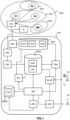
- FIG. 1 represents a global architecture of a PTF system or platform for managing a set of AI Artificial Intelligence models MD1, MD2, ... MDN, with N non-zero integer, previously trained to predict for a future time period an evolution of measurements made by data sensors S1, S2, ...SM, with M non-zero integer, placed in a real environment ENV, from observations or measurements made by these data sensors for a given time period.
- the sensor measurements are collected by a COLL collector.
- the future time period considered can be a quarter of an hour, half an hour, one hour, etc.
- its duration can vary depending on the applications. For the previous example, it can be at least as long as the future time period.
- the AI models in question can be of various types, among which we cite, as purely illustrative examples, convolutional neural networks (CNN), recurrent neural networks (RNN), decision trees, linear regression models, etc.
- CNN convolutional neural networks
- RNN recurrent neural networks
- decision trees decision trees
- linear regression models etc.
- the training of these models is supervised and carried out from a history of measurement data from data sensors stored in memory.
- the data sensors are grouped into a plurality of groups GP 1 to GP N , generally by type. Note that they can also be grouped according to common statistical properties of the time series of measurement data that they collect, each group GP i being associated with a given AI MD i model. In other words, this same AI MD i model is implemented to predict a temporal evolution of the measurement data of all the sensors of the group GP i .
- the PTF system comprises several components that interact with each other to enable management of these AI models, in particular to maintain and evolve them.
- the PTF system includes at least one memory in which one or more versions of the AI models, MD 1 to MD N , are stored.
- This is an example of a model registry RGY (from the English, "model registry").
- model registry RGY (from the English, "model registry").
- Model registries are often used in environments shared by several teams working on AI projects, and they play a crucial role in the model lifecycle. In particular, they allow the different versions of AI models to be stored centrally. This facilitates the search, retrieval, and management of models. They also facilitate the management of different versions of a model, recording the changes made, the hyperparameters used, the associated datasets, etc.
- model registry allows for more efficient collaboration by avoiding conflicts, sharing results, and ensuring consistency across models used across different projects. By recording all the information needed to reproduce a model (source code, data, hyperparameters, etc.), a model registry facilitates the reproducibility of experiments and results.
- These model registries can also offer built-in deployment features, making it easy to deploy a trained model to production environments. They can also include features to monitor model performance in production, collecting metrics such as precision, recall, etc. They can also integrate permission management mechanisms, allowing control over who can access, modify, or deploy a specific model.
- a model registry simplifies the management, tracking, and collaboration around AI models, contributing to more efficient use of resources and higher-quality results. It's an important tool in the development and deployment of AI-powered applications, especially in complex environments where multiple teams interact.
- the PTF system also comprises a source module SRC configured to obtain observation or measurement data from the plurality of data sensors S1, S2, ..., SM of the ENV environment, for example via the COLL collector.
- this measurement data takes the form of time series.
- the frequency of collection of loT sensor data depends largely on the application context, the specific needs of the system and the operational constraints. These include the nature of the data, constraints related to the energy consumption of the sensors which can be powered by a battery, their storage capacity, constraints related to the nature of the monitored events, data transmission cost constraints (for example, pricing can be based on the volume of data transmitted for certain communication networks), etc.
- a preliminary analysis of the specific needs of the application and the implementation of pilot tests make it possible to determine the optimal data collection frequency.
- IoT systems can be configured to dynamically adjust collection frequency based on changing conditions or specific needs. For example, sensors in the wastewater and stormwater collection network collect an average of one measurement per minute. These are then aggregated every quarter of an hour to reduce the size of the historical measurement data recorded per sensor.
- the PTF system also includes a PRC data processing module configured to access the source data obtained from the data sensors by the SRC module and execute one or more processing operations on this data, and a loading module to load the processed data into a DHM data table stored in a DWH decision-making data warehouse of the PTF system, for example a relational database.
- the DHM data table groups together all the observations measured by the sensors S1 to SM, or measurement history, since their commissioning in the ENV environment.
- the measurement data are used to generate data tables ready to be used for the management of the MD 1 to MD N AI models by the PTF system, in particular their training and evaluation.
- the DHM data table has the structure required to extract input data to be presented to one of the AI models and data with the value of labels, representative of the reality on the ground.
- the real ENV environment is an industrial environment, for example a wastewater and rainwater collection network.
- Thousands of data sensors are placed throughout the network to measure physical quantities such as temperature, pressure, water level, etc., over successive time periods.
- the goal of using AI models is to automatically obtain predictions of an evolution of these different measurements for a future period, from which a malfunction can be predicted and anticipated. For example, it happens that a blockage phenomenon occurs due to the presence of a tree root that obstructs a pipe. This situation can be very problematic, for example when wastewater overlaps with rainwater and overflows into nature, causing soil pollution.
- the temperature, pressure, and water level measurements collected over time by the plurality of data sensors are received by the PTF system, processed, and then stored in the DHM data table.
- This data history is intended to be used for learning MD1 to MDN AI models and for their evaluation by the PTF system.
- the PTF system also includes a TRN module for training AI models using a training data set created for each GP group i from the measurement data of a given sensor in this group, stored in the DHM measurement data table.
- This module is configured to implement an initial training phase, then once the AI model has been put into production in the ENV environment, regular retraining phases.
- the PTF system also includes an EVL module for evaluating AI models, once the learning phase (training or retraining) is complete. For each AI model, it is based on an evaluation dataset also including measurement data from a sensor in the group and the associated labels. Of course, to avoid any bias, the sets used for training and evaluation are disjoint. It should be noted that generally, the evaluation sets are created upstream of the project, i.e. before the initial training and deployment phase of the AI models. For example, such a set includes measurements collected by a sensor in the group, especially the history.
- the evaluation module aims to verify that the AI model that has just been trained is sufficiently efficient, i.e. that it predicts the measurements of the sensors in the group well enough to be deployed. In particular, when replacing an earlier version of the AI model already in production with a newer version, the EVL module is configured to verify that the new version of the AI model is at least as performant as the earlier version, before it is deployed.
- the PTF system also comprises a DPL module for making available and deploying the AI models once trained and evaluated.
- DPL module is for example connected to a communication module (not shown) of the PTF system, via which the AI model is transmitted to a data server SV of the environment ENV, configured to use it to predict sensor measurements for a following time period from data collected for a previous time period.
- the data server SV comprises at least one memory for storing the AI models MD 1 to MD N and at least one processor for executing them.
- the AI models are deployed at a remote host and connected to the local server SV by via a telecommunications network (not shown).
- the AI models are executed on remote servers, for example in a server farm or as a service accessible via a cloud network (from the English, "cloud computing").
- the PTF system further comprises a device 100 for managing artificial intelligence models MD1, MD2, ..., MDN trained to predict measurements collected by the plurality of sensors placed in the real environment ENV, said prediction models being stored in the memory of the PTF computer system, for example in the model register RGY, the device 100 being configured to obtain measurements collected by a reference sensor of a group of at least one of said data sensors, for a past time period, said so-called historical measurements being stored in the data table DHM, obtain predicted measurements of said reference sensor using a said prediction model associated with said group of sensors for a following time period, said predicted measurements being stored in a historical prediction data table DHP of the data warehouse DWH, compare the predicted measurements for the following time period with measurements collected by said reference sensor for the following time period, when a determined difference between the compared measurements is greater than a given prediction drift threshold, select a new reference sensor for said group, the new selected reference sensor being the data sensor of said group associated with the lowest difference, and retraining the AI model from the historical measurement data collected by the new reference sensor.
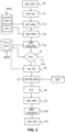
- the device 100 implements a method for managing artificial intelligence models MD1, MD2...MDN which will be described below in relation to the FIG. 3 .
- the PTF system also includes a LOG module for creating and transmitting reports or event logs in which detected cases of drift are recorded.
- the generated event reports can also be used by a BI-APP application for generating dashboards including key performance indicators (KPIs) relating to the operation of the PTF system and/or the AI models it manages.
- KPIs key performance indicators
- the PTF system also includes user interface means, not shown, allowing a user U1, for example an analyst (from the English, “data scientist”), to obtain these dashboards.
- a central control module comprising one or more processors, makes it possible to control the operation of the different elements of the PTF system.
- the PTF system can belong to a company in charge of monitoring the ENV environment, for example a water authority, and be hosted on site or, alternatively, be hosted remotely, for example in public infrastructures on the internet ("public cloud" in English).
- the PTF system is implemented by hardware and software means.
- the hardware means may include one or more processors.
- the software means may include applications, software, computer programs, and/or a set of program instructions and data.
- the PTF system also comprises a module or agent UPD update configured to update data stored in memory and necessary for the operation of the PTF system.
- This is for example configuration data, specifying for example a similarity measure, a drift threshold, the reference sensor of each group of data sensors etc.
- An example of implementation is now detailed in relation to the FIG. 2 .
- the PTF system comprises a GVP governance and/or configuration computer file, stored in MEM memory.
- This computer file may be a declarative file, for example of CSV, YAML, XML or other type.
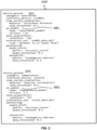
- a purely illustrative example of a GVP governance file is presented on the FIG. 2 . It contains information related to groups GP 1 , GP 2 , ..., GP N , with N non-zero integer, of data sensors, in the example of the FIG.
- the group GP 1 comprises two sensors sn001 and sn002 belonging to the “water level” category.
- the associated AI model MD 1 is a “water level model” and version 1.0 is used. As for the GP 2 group, it also includes two data sensors sn111 and sn112 of the temperature sensor type.
- the active AI model in production is a temperature model in its version 1.2.
- the specified performance threshold is 0.95.
- a performance level is considered acceptable (and the AI model can be put into production) based on a score equal to the performance threshold of a similarity measure, such as the Jaccard index, a drift threshold, a first weight associated with the KPI and a second weight associated with the keywords.
- a similarity measure such as the Jaccard index, a drift threshold, a first weight associated with the KPI and a second weight associated with the keywords.
- each element of the PTF system and, in particular, the device 100 can access the GVP file and read operational parameters for controlling operations or tasks to be implemented.
- the GVP file is modifiable, which makes it possible to evolve the data sensors constituting a group of sensors, the version of the AI model used and/or the operational parameters of the PTF system and in particular of the device 100, without it being necessary to modify a source code allowing the execution of tasks and operations by the PTF system.
- the central control module (not shown) is arranged to control the operation of the PTF system. It may include a task orchestrator for scheduling the tasks executed by the PTF system.
- the GVP governance computer file is read, which allows the device 100 to obtain the latest version of the operational parameters that it stores.
- a step E1 information relating to a group GP i , with i between 1 and N, of data sensors to be processed is obtained.
- the management method for example predetermined, which guarantees that the operation of each is checked regularly.
- the supervision of a group of sensors is triggered once a month, the group of sensors to be supervised being chosen randomly or according to a given order.
- it may be the orchestrator which commands the device 100 to supervise a given group.
- the group GP1 of water level sensors of the FIG.2 we take the example of the group GP1 of water level sensors of the FIG.2 .
- a reference data sensor RS associated with the GP group i is identified among the sensors attached to the GP group i , as well as an MD AI model i associated with this group i. It is assumed that it is in production in the ENV environment and that the DHP prediction historical data table stored in the DWH warehouse is continuously populated with the data that the MD model i predicts from the data measured by the reference sensor RS.
- measurement data collected by this reference sensor Sm over a given time period are obtained from the historical data table DHM stored in the data warehouse DWH.
- the given time period corresponds to the period elapsed since the last supervision of the MD model i .
- its value is one or more months.
- the data predicted for the same time period by the MDi model are obtained from the DHP data table comprising the prediction history of this model.
- the sensor measurements can be collected by the COLL collector at a given collection frequency, for example every quarter of an hour, and then transmitted to the PTF system for managing the AI models with a different transmission frequency, for example equal to once a month.
- step E4 the measurement data obtained in E2 are compared with the predicted data obtained in E3. It is understood that this involves comparing time series data and evaluating a measure of distance/similarity between them.
- the technique(s) to be used is, for example, specified in the governance file among the operational parameters associated with the GPi sensor group and the supervision task considered. In this case, the operation carried out is a monitoring operation. In the example of the FIG. 2 , for the GP1 group, the precision or distance measure considered is an “accuracy score”.
- model_threshold a performance threshold of the model (on the FIG.2 , in English, "model_threshold"
- model_threshold a performance threshold of the model
- an event report indicating compliant operation is generated by the LOG module and made available.
- the AI MDi model is not considered compliant (a drift has been detected).
- a corrective action is implemented.
- a new reference sensor is searched for within the group. To do this, the measurement data and the associated predicted data for the time period considered are obtained for the other sensors in the group than the current reference sensor and the one that obtains the best model performance score is selected to become the new reference sensor RS' for this group.
- a retraining phase of the MD i model is triggered at the TRN module, from a training set formed from part of the historical measurement data associated with the new reference sensor stored in the DHM data table. At the end of this retraining phase, it is tested from a test set, distinct from the training set.
- E8 once the retraining of the MD i model is complete, an evaluation of the retrained model is triggered from the EVL module using a third data set, called the evaluation set.
- this evaluation set is constituted upstream, that is to say at the constitution of the group of sensors, for example by an analyst and it is not intended to be modified subsequently.
- the path to access this evaluation set is configured beforehand, for example specified in the GVP governance file.
- a performance score is evaluated and compared to the one obtained by the previous version of the MD i model (currently in production).
- a decision rule for example specified in the GVP governance file, is to replace the previous version of the AI model with the new one as soon as the new version obtains a performance score at least as good as that of the previous version.
- the method described here comprises the prior updating of the evaluation set stored in memory by adding to it a portion of the measurement data (and associated labels) collected by the old reference sensor RS and for which a drift of the model has been detected. In this way, it is guaranteed that the new versions of the AI models that will be deployed follow the evolution of the measurements and therefore continuously adapt to the environment to be supervised.
- a constraint to be respected when constituting the training and test sets of the MD i AI model is not to include sensor measurements of the GP i group that are already present in the evaluation set. Respecting this constraint makes it possible to avoid introducing a bias in the comparative evaluation of the performances of the new version of the AI model with the previous one.
- the new version of the MD i model is put into production instead of the current version.
- it is transmitted by the DPL deployment module of the PTF system to the SV server of the environment via communication means of the PTF system, then loaded into a memory, instead of the previous version in order to be executed by a processor of a data server.
- it is transmitted to a remote server of the ENV environment, hosted in a cloud network infrastructure.
- this new version is transmitted to the server in question in a Pickle format file.
- the new version of the AI model does not pass the evaluation test, the version of the AI model in production remains unchanged.
- a LOG event report is generated so that an analyst in charge of monitoring the PTF system is informed of this failure and can determine whether an update of other modules is necessary. For example, he may decide to modify the processing implemented on the measurement data by the PRC module or the configuration parameters of the AI model itself.
- a LOG event report is created, stored in memory and possibly notified to a UT2 user, for example an analyst in charge of maintaining the PTF system.
- an update of the GVP governance file is triggered at the UPD update agent level. It includes the update of the version of the MD i model, and the identifier of the new RS' reference sensor.
- the process just described monitors AI models deployed in a real environment and implements corrective actions in the event of a detected drift in the performance of one of these models.
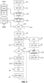
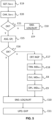
- a step E12 measurement data collected by the reference sensor RS, for two distinct time periods, are obtained from the historical data table DHM for the group GP j .
- the two time periods are consecutive or not. Since it is a question of detecting whether the measurements of the reference sensor have kept the same statistical properties or not, it may be relevant to consider a first recent or current time period, for example the hour, day, week or month before and a second time period a little older, for example the hour, day, week or month before the first period.
- the measurements collected by said reference sensor RS for the two time periods are compared, using a given distance metric, for example the one specified by the GVP governance file for the detection of data drift in relation to the GP sensor group j considered.
- a given distance metric for example the one specified by the GVP governance file for the detection of data drift in relation to the GP sensor group j considered.
- E14 we determine whether the obtained distance is greater than a given drift threshold. For example, this threshold was previously obtained from the GVP governance file.
- the data drift threshold in the example of the FIG.2 , in English, "data_threshold" is set to 0.3. If not, it is decided that there is no drift in the measurement data of the reference sensor RS and the process stops. The device 100 does not perform any operation and waits to re-execute a next phase of supervision of the AI model or the data.
- a new reference sensor RS' is selected for said group, during a new execution of step E6 already described.
- the new reference sensor RS' selected is the one associated with the smallest distance calculated using the previous metric.
- the MD model j is retrained, then tested during a new execution of step E7 already described in relation to the FIG.3 , from a training data set and a test set each comprising a part of the historical measurement data stored for the new reference sensor RS'.
- this update includes at least the update of the information data relating to the GP group j which was the subject of the supervision: new reference sensor identifier RS', and new version of the AI model.
- an update of the information relating to the sensor group to which the old RS reference sensor was integrated is carried out, including an addition of the identifier of this additional sensor.
- this evaluation set is automatically formed from a part of the measurement data history of the RS sensor, which was not used to constitute the training and test sets.
- the steps just described perform a phase of monitoring the measurement data collected by the reference sensor of a group of sensors placed in the ENV environment. They contribute to detecting a possible drift, for example due to the occurrence of a new behavior of the ENV environment, for example in the presence of a new climatic phenomenon or other.
- a step E19 information relating to the addition of the additional data sensor S M+1 in the ENV environment is obtained.
- the device 100 can obtain this information in different ways. For example, it receives a notification from the control module or the orchestrator of the PTF system. Such a notification comprises at least one identifier of the added sensor S M+1 . It can also comprise a link to historical measurement data collected by this sensor S M+1 which have been recorded in the DHM data table stored in the data warehouse.
- the device 100 can be configured to regularly read a data register in which information relating to the fleet of sensors of the ENV environment is stored, detect this addition and obtain the associated information that it will need to execute the supervision operations of the AI models put into production in the ENV environment.
- the measurement data history associated with the additional sensor S M+1 includes sufficient data to be integrated into the PTF system, based on one or more conditions specified in the file of GVP governance. They are, for example, stored in the “data_acquisition” section. On the FIG.2 , for example, for group GP 1 , the requirement is to have three years of historical measurement data. Of course, other conditions, e.g. volume, frequency, etc. can be taken into consideration when deciding whether or not to integrate the additional sensor.
- E21 if the condition is not met, the additional sensor is not integrated into a group of sensors managed by the PTF system and the process stops.
- a LOG event report is generated in E10 and made available to a U2 analyst. In this way, he will be informed that the measurement data of this sensor S M+1 will not be used to predict the evolution of the operation of the ENV environment and predict possible malfunctions. This event report can also indicate the reason for the rejection of the sensor S M+1
- the historical measurement data obtained are compared respectively with those of the reference sensors of the plurality of sensor groups GP 1 to GP N currently in production in the environment.
- the similarity measure used to perform this comparison is that specified in memory for each group, for example, in the GVP governance file. It is assumed for example that the sensor S M+1 is assigned to the group for which the similarity measure is the greatest, respectively the difference is the smallest, while respecting the condition linked to the threshold specified in the GVP governance file.
- step E16 if a group has been found, we move on to step E10 for generating a LOG event report. Otherwise, step E17 for creating an additional group GP N+1 is implemented. In this case, sensor S M+1 is the only member of the group and automatically becomes its reference sensor.
- the training of a new AI model MD N+1 is triggered at the TRN module using training and test sets consisting of a part of the measurement data history of the new sensor S M+1 .
- the new AI model is evaluated in E8 using an evaluation set, which, according to one or more exemplary embodiments, may consist of another part of the measurement data history of the new sensor S M+1 .
- the new AI model is deployed in the real ENV environment.
- a LOG event report is generated in E10.
- an update of the GVP governance file is triggered in E11 at the UPD update agent. This update consists in particular of specifying the information relating to the addition of the additional sensor in an existing group or the addition of a new group including the additional sensor.
- the steps just described take into account an additional data sensor for monitoring the ENV environment. They help determine whether the sensor in question has a data history satisfying sufficient predetermined conditions, in particular age, to be taken into account and whether it can be integrated into a group of sensors. existing, a new group being created specifically for it if necessary. In this way, the evolution of the means deployed for the supervision of the ENV environment is taken into account to keep the PTF system for managing IA models up to date.
- Each described function, block, step may be implemented in hardware, software, firmware, middleware, microcode, or any suitable combination thereof. If implemented in software, the functions or blocks of the block diagrams and flowcharts may be implemented by computer program instructions/software codes, which may be stored or transmitted on a computer-readable medium, or loaded onto a general-purpose computer, a special-purpose computer, or other programmable processing device and/or a system, such that the computer program instructions or software codes executing on the computer or other programmable processing device create the means to implement the functions described in this specification.
- FIG. 6 illustrates an example of a hardware structure of a device 100 for managing artificial intelligence models previously trained to predict data sensor measurements for a subsequent time period, from measurement data collected for a previous time period, according to one or more embodiments.
- the device 100 is configured to implement all the steps of the method described in this document. Alternatively, it could also implement only some of these steps.
- the device 100 comprises at least one processor 110 and at least one memory 120.
- the device 100 may also comprise one or more communication interfaces.
- the device 100 comprises network interfaces 130 (e.g., network interfaces for accessing a wired/wireless network, including an Ethernet interface, a WIFI interface, etc.) connected to the processor 110 and configured to communicate via one or more wired/wireless communication links and user interfaces 140 (e.g., a keyboard, a mouse, a display screen, etc.) connected to the processor.
- the device 100 may also comprise one or more media readers 150 for reading a computer-readable storage medium (e.g., a digital storage disk (CD-ROM, DVD, Blue Ray, etc.), a USB flash drive, etc.).
- the processor 110 is connected to each of the other aforementioned components in order to control their operation.
- the memory 120 may include random access memory (RAM), cache memory, non-volatile memory, backup memory (e.g., programmable or flash memories), read only memory (ROM), a hard disk drive (HDD), a solid state drive (SSD), or any combination thereof.
- RAM random access memory
- ROM read only memory
- HDD hard disk drive
- SSD solid state drive
- the ROM of the memory 120 may be configured to store, among other things, an operating system of the device 100 and/or one or more computer program codes of one or more software applications.
- the RAM of the memory 120 may be used by the processor 110 for temporary storage of data.
- the processor 110 may be configured to store, read, load, execute and/or otherwise process instructions stored in a computer-readable storage medium and/or in the memory 120 such that, when the instructions are executed by the processor, the device 100 executes one or more or all of the steps of the management method, described in this document.
- Means implementing a function or a set of functions may correspond in this document to a software component, a hardware component or a combination of components hardware and/or software, capable of implementing the function or set of functions, as described below for the means concerned.
- the present description also relates to an information medium readable by a data processor, and comprising instructions of a program as mentioned above.
- the information carrier may be any material means, entity or device, capable of storing the instructions of a program as mentioned above.
- Usable program storage media include ROM or RAM memories, magnetic storage media such as magnetic disks and magnetic tapes, hard disks or optically readable digital data storage media, or any combination of these media.
- the computer-readable storage medium is not transient.
- the information medium may be a transient medium (e.g., a carrier wave) for the transmission of a signal (electromagnetic, electrical, radio, or optical signal) carrying the program instructions.
- a signal electromagnetically, electrical, radio, or optical signal
- This signal may be conveyed via a suitable transmission medium, whether wired or wireless: electrical or optical cable, radio or infrared link, or by other means.
- An embodiment also relates to a computer program product comprising a computer-readable storage medium having stored thereon program instructions, the program instructions being configured to cause the host device (e.g., a computer) to implement some or all of the steps of the method described herein when the program instructions are executed by one or more processors and/or one or more programmable hardware components of the host device.
- the host device e.g., a computer
- the system, device and method that have just been described make it possible to automatically supervise the operation of artificial intelligence models previously trained and put into production to each predict the evolution of the measurements of a group of sensors among a plurality of data sensors deployed in a real environment, for example an industrial installation, with a view to preventing possible malfunctions of this environment.
- the embodiments that have been presented make it possible to verify the level of performance of the AI models put into production, to retrain them as soon as necessary to maintain optimal performance over time.
Landscapes
- Engineering & Computer Science (AREA)
- Physics & Mathematics (AREA)
- Theoretical Computer Science (AREA)
- Software Systems (AREA)
- Artificial Intelligence (AREA)
- Evolutionary Computation (AREA)
- Mathematical Physics (AREA)
- General Physics & Mathematics (AREA)
- Medical Informatics (AREA)
- Data Mining & Analysis (AREA)
- Computer Vision & Pattern Recognition (AREA)
- Computing Systems (AREA)
- General Engineering & Computer Science (AREA)
- Automation & Control Theory (AREA)
- Testing Or Calibration Of Command Recording Devices (AREA)
Priority Applications (2)
| Application Number | Priority Date | Filing Date | Title |
|---|---|---|---|
| EP23307148.9A EP4567687A1 (de) | 2023-12-06 | 2023-12-06 | Verfahren, vorrichtung und computersystem zur verwaltung von modellen künstlicher intelligenz zur vorhersage von sensormessungen |
| US18/971,349 US20250190870A1 (en) | 2023-12-06 | 2024-12-06 | Method, device and computer system for managing artificial intelligence models for predicting sensor measurements |
Applications Claiming Priority (1)
| Application Number | Priority Date | Filing Date | Title |
|---|---|---|---|
| EP23307148.9A EP4567687A1 (de) | 2023-12-06 | 2023-12-06 | Verfahren, vorrichtung und computersystem zur verwaltung von modellen künstlicher intelligenz zur vorhersage von sensormessungen |
Publications (1)
| Publication Number | Publication Date |
|---|---|
| EP4567687A1 true EP4567687A1 (de) | 2025-06-11 |
Family
ID=90473282
Family Applications (1)
| Application Number | Title | Priority Date | Filing Date |
|---|---|---|---|
| EP23307148.9A Pending EP4567687A1 (de) | 2023-12-06 | 2023-12-06 | Verfahren, vorrichtung und computersystem zur verwaltung von modellen künstlicher intelligenz zur vorhersage von sensormessungen |
Country Status (2)
| Country | Link |
|---|---|
| US (1) | US20250190870A1 (de) |
| EP (1) | EP4567687A1 (de) |
Families Citing this family (1)
| Publication number | Priority date | Publication date | Assignee | Title |
|---|---|---|---|---|
| US20260088970A1 (en) * | 2025-07-25 | 2026-03-26 | Joshua A Wright | Hybrid AI Failover and Secure Field-Data Capture System with Shadow-Mode Validation and Training-to-Inference Reassignment |
Citations (2)
| Publication number | Priority date | Publication date | Assignee | Title |
|---|---|---|---|---|
| FR2977422A1 (fr) * | 2011-06-30 | 2013-01-04 | France Telecom | Configuration automatique d'entites physiques dans un systeme de supervision et de controle |
| EP4102253A1 (de) * | 2021-06-10 | 2022-12-14 | Thales | Verfahren und vorrichtung zur auswahl von sensorressourcen eines multisensorsystems |
-
2023
- 2023-12-06 EP EP23307148.9A patent/EP4567687A1/de active Pending
-
2024
- 2024-12-06 US US18/971,349 patent/US20250190870A1/en active Pending
Patent Citations (2)
| Publication number | Priority date | Publication date | Assignee | Title |
|---|---|---|---|---|
| FR2977422A1 (fr) * | 2011-06-30 | 2013-01-04 | France Telecom | Configuration automatique d'entites physiques dans un systeme de supervision et de controle |
| EP4102253A1 (de) * | 2021-06-10 | 2022-12-14 | Thales | Verfahren und vorrichtung zur auswahl von sensorressourcen eines multisensorsystems |
Also Published As
| Publication number | Publication date |
|---|---|
| US20250190870A1 (en) | 2025-06-12 |
Similar Documents
| Publication | Publication Date | Title |
|---|---|---|
| US11237898B2 (en) | Automatic model-based computing environment performance monitoring | |
| FR3098938A1 (fr) | Procédé et dispositif de détermination d’une valeur d’indice de performance de prédiction d’anomalies dans une infrastructure informatique à partir de valeurs d’indicateurs de performance | |
| EP3767558B1 (de) | Verfahren und vorrichtung zur bestimmung einer geschätze dauer bis einem technischen vorfall in einer it-infrastruktur basierend auf leistungsindikatorwerten | |
| EP3846087A1 (de) | Verfahren und system zur auswahl eines lernmodells innerhalb einer vielzahl von lernmodellen | |
| US20240119364A1 (en) | Automatically generating and implementing machine learning model pipelines | |
| AU2018203375A1 (en) | Method and system for data based optimization of performance indicators in process and manufacturing industries | |
| WO2019209618A1 (en) | Computer system and method for creating a supervised failure model | |
| US20190057307A1 (en) | Deep long short term memory network for estimation of remaining useful life of the components | |
| EP3059682B1 (de) | Datenverarbeitungs- und modellierungssystem für die analyse des energieverbrauchs eines standorts | |
| WO2021021318A1 (en) | Diagnosing & triaging performance issues in large-scale services | |
| FR3098940A1 (fr) | Procédé et dispositif de détermination d’une valeur de risque d’incident technique dans une infrastructure informatique à partir de valeurs d’indicateurs de performance | |
| FR2957097A1 (fr) | Systeme et procede de surveillance de ressources dans un reseau de distribution d'eau | |
| CN117170915A (zh) | 数据中心设备故障预测方法、装置和计算机设备 | |
| KR20260025830A (ko) | 머신 러닝 및 통계 모델을 사용한 고급 예측을 위한 시스템 및 방법 | |
| EP4567687A1 (de) | Verfahren, vorrichtung und computersystem zur verwaltung von modellen künstlicher intelligenz zur vorhersage von sensormessungen | |
| EP3767474B1 (de) | Verfahren zur analyse des ressourcenverbrauchs einer it-infrastruktur, alarm und dimensionierung | |
| EP3846047A1 (de) | Verfahren und system zur identifizierung relevanter variablen | |
| WO2021009364A1 (fr) | Procédé d'identification de données aberrantes dans d'un jeu de données d'entrée acquises par au moins un capteur | |
| FR3018933A1 (fr) | Procede de determination de l'etat d'un equipement d'aeronef. | |
| Vervlimmeren et al. | Scalable SCADA-driven failure prediction for offshore wind turbines using autoencoder-based NBM and fleet-median filtering | |
| CN117893019B (zh) | 投放企业信息化管控系统及操作风险管控方法 | |
| EP4033361B1 (de) | Verfahren und vorrichtung zur bestimmung mindestens einer maschine, die an einer in einer komplexen it-infrastruktur entdeckten anomalie beteiligt ist | |
| FR2970796A1 (fr) | Procede de traitement de messages de pannes generes dans un appareil a systemes complexes | |
| EP4475044B1 (de) | Verfahren zur parametrierung einer datenverarbeitungsleitung | |
| US20260121967A1 (en) | Regression detection using indicators from dependent services |
Legal Events
| Date | Code | Title | Description |
|---|---|---|---|
| PUAI | Public reference made under article 153(3) epc to a published international application that has entered the european phase |
Free format text: ORIGINAL CODE: 0009012 |
|
| STAA | Information on the status of an ep patent application or granted ep patent |
Free format text: STATUS: THE APPLICATION HAS BEEN PUBLISHED |
|
| AK | Designated contracting states |
Kind code of ref document: A1 Designated state(s): AL AT BE BG CH CY CZ DE DK EE ES FI FR GB GR HR HU IE IS IT LI LT LU LV MC ME MK MT NL NO PL PT RO RS SE SI SK SM TR |
|
| STAA | Information on the status of an ep patent application or granted ep patent |
Free format text: STATUS: REQUEST FOR EXAMINATION WAS MADE |
|
| 17P | Request for examination filed |
Effective date: 20251120 |
|
| GRAP | Despatch of communication of intention to grant a patent |
Free format text: ORIGINAL CODE: EPIDOSNIGR1 |
|
| STAA | Information on the status of an ep patent application or granted ep patent |
Free format text: STATUS: GRANT OF PATENT IS INTENDED |
|
| INTG | Intention to grant announced |
Effective date: 20260202 |
|
| RIC1 | Information provided on ipc code assigned before grant |
Ipc: G06N 20/00 20190101AFI20260126BHEP Ipc: G06N 3/044 20230101ALN20260126BHEP Ipc: G06N 3/0464 20230101ALN20260126BHEP Ipc: G06N 3/09 20230101ALN20260126BHEP |