EP4567740A1 - Modification d'un modèle associé à des structures anatomiques - Google Patents
Modification d'un modèle associé à des structures anatomiques Download PDFInfo
- Publication number
- EP4567740A1 EP4567740A1 EP23214153.1A EP23214153A EP4567740A1 EP 4567740 A1 EP4567740 A1 EP 4567740A1 EP 23214153 A EP23214153 A EP 23214153A EP 4567740 A1 EP4567740 A1 EP 4567740A1
- Authority
- EP
- European Patent Office
- Prior art keywords
- point
- computer
- points
- contour
- anatomical
- Prior art date
- Legal status (The legal status is an assumption and is not a legal conclusion. Google has not performed a legal analysis and makes no representation as to the accuracy of the status listed.)
- Pending
Links
Images



Classifications
-
- G—PHYSICS
- G06—COMPUTING OR CALCULATING; COUNTING
- G06T—IMAGE DATA PROCESSING OR GENERATION, IN GENERAL
- G06T19/00—Manipulating three-dimensional [3D] models or images for computer graphics
- G06T19/20—Editing of three-dimensional [3D] images, e.g. changing shapes or colours, aligning objects or positioning parts
-
- G—PHYSICS
- G06—COMPUTING OR CALCULATING; COUNTING
- G06T—IMAGE DATA PROCESSING OR GENERATION, IN GENERAL
- G06T2200/00—Indexing scheme for image data processing or generation, in general
- G06T2200/24—Indexing scheme for image data processing or generation, in general involving graphical user interfaces [GUIs]
-
- G—PHYSICS
- G06—COMPUTING OR CALCULATING; COUNTING
- G06T—IMAGE DATA PROCESSING OR GENERATION, IN GENERAL
- G06T2210/00—Indexing scheme for image generation or computer graphics
- G06T2210/41—Medical
-
- G—PHYSICS
- G06—COMPUTING OR CALCULATING; COUNTING
- G06T—IMAGE DATA PROCESSING OR GENERATION, IN GENERAL
- G06T2219/00—Indexing scheme for manipulating 3D models or images for computer graphics
- G06T2219/20—Indexing scheme for editing of 3D models
- G06T2219/2021—Shape modification
Definitions
- the invention relates to anatomical models of anatomical structures and, in particular, to methods and apparatuses for manipulating a reference model relative to such an anatomical model.
- computer models are used to view or measure parts of a body (e.g., of a human or animal) and/or simulate a procedure to be carried out in respect of the body part. For example, prior to performing a particular medical procedure, it may be advantageous to use a computer model to measure an anatomical structure in a person's body.
- an annuloplasty procedure may be performed in relation to a tricuspid valve of a person's heart.
- a procedure involves attaching an implant (e.g., an annuloplasty band) to the right atrium of the person's heart.
- an implant e.g., an annuloplasty band
- Prior to performing the procedure there is a need to measure a circumference part of the circumference) of the right atrium with a fixed distance (e.g., a distance of 4mm according to one example) along the atrial wall from the segmented tricuspid annulus.
- Such measurements are historically performed manually by a medical professional. However, such a manual measurement may be inaccurate, for example if the medical professional measures the fixed distance inaccurately. An inaccurate measurement can lead to the selection of an inappropriately sized annuloplasty band, which could lead to delays while a more appropriately-sized band is sourced. In another example, the inappropriately-sized band may be implanted into the subject, leading to a poor outcome from the procedure.
- the inventors of the present disclosure have identified a downside of existing methods of exploring anatomical objects of a subject, due to the possible inaccuracies and potential errors in identifying particular areas or regions of the anatomical object and, in some cases, performing measurements or other tasks in respect of the anatomical object, for example prior to performing a medical procedure.
- the inventors have recognised that one or more of the above-identified issues can be mitigated or overcome by introducing a mechanism that enables accurate exploration and/or manipulation of a computer model of an anatomical object or structure.
- a solution identified by the inventors involves introducing a reference model that is positioned with respect to the part of an anatomical model of an anatomical structure, and enabling a user to manipulate parts of the reference model within defined constraints that serve to maintain a degree of accuracy.
- a computer-implemented method comprising receiving an anatomical model of an anatomical structure, the anatomical model comprising a region having a first contour comprising a first plurality of points; receiving a reference model having a second contour comprising a second plurality of points, each point of the second plurality being in correspondence with a respective point of the first plurality; positioning the reference model with respect to the region of the anatomical model such that each point of the second plurality is offset a predetermined distance from its corresponding point of the first plurality; and providing a user control enabling a user to modify a relative angular position of a first point of the second plurality around the position of its corresponding point of the first plurality in a plane containing the first point of the second plurality and said corresponding point of the first plurality.
- the plane may be substantially transversal to a best fit plane of the first contour.
- the method may, in some embodiments, further comprise providing data indicative of the relative positions of the first point of the second plurality and its corresponding point of the first plurality for presentation to a user.
- the method may further comprise receiving, via the user control, an indication of a modification of the relative angular position of a given point of the second plurality around the position of its corresponding point of the first plurality.
- the method may further comprise, responsive to receiving an indication of a modification of the relative angular position of the given point of the second plurality, adjusting a position of at least one point of the second plurality adjacent to the given point.
- an amount of adjustment of the position of the at least one point of the second plurality is in accordance with a Gaussian distribution.
- Positioning the reference model with respect to the region of the anatomical model may, in some embodiments, comprise estimating an initial position of each point of the second plurality of points relative to its corresponding point of the first plurality.
- the second contour may be an open contour.
- the second contour may be substantially c-shaped.
- the method may, in some embodiments, further comprise providing a user control enabling a user to modify a position of at least one end point of the second plurality of points of the second contour.
- the reference model comprises a model of an anatomical implant.
- the method may further comprise determining, based on the positions of the points of the second plurality, a length of the anatomical implant.
- an apparatus comprising a processor configured to perform the steps of the methods disclosed herein.
- the apparatus may further comprise a display configured to display a representation of at least part of the anatomical structure, an indication of the first point of the second plurality of points relative to the anatomical structure and the corresponding point of the first plurality of points relative to the first point and to the anatomical structure.
- the apparatus may further comprise a user interface configured to enable a user to modify at least one of: a relative angular position of the first point of the second plurality around the position of its corresponding point of the first plurality; a position of one or more points of the first plurality of points; and a position of one or more points of the second plurality of points.
- a computer program product comprising a non-transitory computer-readable medium, the computer-readable medium having computer-readable code embodied therein, the computer-readable code being configured such that, on execution by a suitable computer or processor, the computer or processor is caused to perform steps of the methods disclosed herein.
- the present disclosure provides a mechanism that enables a user to view, explore and accurately manipulate and/or measure part of a reference model relative to an anatomical model of an anatomical structure of a subject.
- the user is able to manipulate a part or parts of the reference model within one or more defined constraints as may be required by the circumstances (e.g., in view of a medical procedure to be performed).
- Examples disclosed herein may be applied to a wide range of scenarios.
- One specific example discussed herein relates to an annuloplasty procedure, which is used to reinforce or tighten a valve of a subject's heart.
- Transcatheter valve procedures are becoming more common in medical practice, and an annuloplasty procedure may be applied to an extensively dilated tricuspid valve, where repair or replacement may no longer be feasible.
- Such a procedure requires extensive planning, which may be performed using a computerised tomography (CT) scan and/or echocardiography.
- CT computerised tomography
- the procedure requires a device (e.g., an annuloplasty band) to be implanted in a specific location relative to the valve, and prior to this, a cardiologist must determine the precise length of the device as well as the placement location.
- a band suitable for use in such a procedure requires around 40 screws to be placed at precise positions along the length of the annuloplasty band, which itself must be sized correctly to match the length of the existing annulus.
- the annuloplasty band should be fitted at a precise distance of 4 mm from the existing annulus along a variable right atrial wall, and it can be difficult to perform such measurements manually in an accurate and in a reproducible manner.
- Fig. 1 shows an example of part of an anatomical structure 102 with an anatomical model 104 and a reference model 106.
- the anatomical structure 102 may be any anatomical structure or object of a subject (e.g., a human or an animal), such as a valve of the subject's heart.
- the anatomical model 104 may be a computer-generated model generated based on a scan of the anatomical structure, for example.
- the anatomical structure 102 is substantially cylindrical in shape and, therefore, the anatomical model 104 is substantially ring-shaped in this example.
- the reference model 106 is a computer-generated model that may be based on the anatomical structure 102 and/or on the anatomical model 104. In some examples, the reference model 106 may be based on a template or on previous reference models used for similar purposes or in respect of similar anatomical structures. In the example shown in Fig. 2 , the reference model 106 is substantially the same shape as the anatomical model 104 (e.g., ring-shaped). However, as will be apparent from other examples discussed herein, the reference model 106 may have a shape that differs from the shape of the anatomical model 104. For example, the reference model 106 may have a shape that matches or is based on part of the anatomical model 104.
- the reference model 106 may be used for various purposes.
- the reference model 106 may be used to measure the size of part of an anatomical structure at a particular location (e.g., at a particular location relative to the anatomical model 104).
- the reference model 106 may be used to represent the position of an implant to be fitted to the anatomical structure 102 in a particular position relative to the anatomical model 104.
- the reference model 106 may be positioned a defined or fixed distance from the anatomical model 104, as represented in Fig. 1 by arrows 108. Each arrow 108 has a defined length, such that the reference model 106 is positioned at a constant distance from the anatomical model 104 along its length.
- the defined separation between the reference model 106 and the anatomical model 104 may vary at different positions, such that part of the reference model 106 is separated from the anatomical model by a first distance while another part of the reference model is separated from the article model by a second distance, different from the first distance.
- Each of the anatomical model 104 and the reference model 106 may have at least a portion that comprises or follows a contour.
- the anatomical model 104 as a contour that substantially follows a wall of the anatomical structure 102.
- the contour of the reference model 106 may, for example, be based on the contour of the anatomical model 104, separated by the defined distance as discussed above.
- the present invention provides a method.
- Embodiments disclosed herein provide a mechanism by which a user is able to manipulate the reference model 106, as discussed below with reference to Fig. 2 .
- Fig. 2 is a flowchart of an example of a method 200.
- the method 200 may comprise a computer-implemented method for manipulating a model.
- One or more steps of the methods disclosed herein may be performed using a processor or multiple processors, such as the processor(s) disclosed herein.
- the processor or processors may form part of one or more computing devices or servers, for example as part of a cloud-computing environment.
- the anatomical model 104 comprises a region that has a first contour comprising a first plurality of points.
- a region of the anatomical model 104 may represent a cylindrical wall of a valve of a subject's heart, and this region of the anatomical model may include a contour extending around the cylindrical wall.
- the contour may, for example, be represented by a line following a path.
- This contour includes a plurality of points which may, for example, be spaced along the contour or line, following the same path.
- the contour may include any number of points in the plurality of points.
- the plurality of points on the contour are used for manipulation of the reference model 106 relative to the anatomical model 104 and, therefore, a larger the number of points in the plurality of points gives rise to a greater level of control by a user over the manipulation of the reference model.
- the method 200 comprises receiving a reference model 106 having a second contour comprising a second plurality of points, each point of the second plurality being in correspondence with a respective point of the first plurality.
- the reference model 106 includes a contour (i.e., the second contour) also having a plurality of points (i.e., the second plurality of points).
- the number of points in the second plurality of points may be the same as the number of points in the first priority of points.
- the contour of the reference model 106 may have a shape similar to, or substantially the same as, the shape of the contour of the anatomical model 104, as shown in the example of Fig. 1 .
- the method 200 comprises, at step 206, positioning the reference model 106 with respect to the region of the anatomical model 104 such that each point of the second plurality is offset a predetermined distance from its corresponding point of the first plurality.
- the reference model 106 may be positioned such that each point along the contour of the reference model is spaced apart by a predetermined or predefined distance (e.g., the distance indicated by the arrows 108 in Fig. 1 ) from its corresponding point of the first plurality of points in the region of the anatomical model.
- the predetermined distance may be set automatically (e.g., based on literature), or may be defined manually, for example by a user selecting a distance or entering a distance using a user interface.
- offset as used herein may be intended to mean "separated by".
- the method 200 comprises providing a user control enabling a user to modify a relative angular position of a first point of the second plurality around the position of its corresponding point of the first plurality in a plane containing the first point of the second plurality and said corresponding point of the first plurality.
- the user control may be provided by means of a user interface for user input device, such as a keyboard, a mouse or a touchpad or touchscreen.
- a user may modify the angular position of a first point of the second plurality (i.e., a first point in the reference model 106) relative to its corresponding point of the first plurality (i.e., its corresponding point in the anatomical model 104).
- the plane containing the first point and the corresponding point may be substantially transversal to the second contour at the first point of the second contour.
- a plane that is "transversal" to the best fit plane of the first contour creates an angle between the plane and the best fit plane of the first contour of 90 degrees. In other words, the plane is perpendicular to the best fit plane of the first contour.
- a plane that is “substantially transversal” to the best fit plane of the first contour creates an angle between the plane and the best fit plane of the first contour of approximately 90 degrees.
- the angle between the plane and best fit plane of the first contour may be within a range of +/-5 degrees from the perpendicular, within a range of +/-10 degrees from the perpendicular, within a range of +/-5% of a 90-degree angle, within a range of +/-10% of a 90-degree angle, or the like. It will be apparent that modification of the position of the first point of the second plurality (i.e., of the reference model 106) by rotating it about the position of its corresponding point of the first plurality (i.e., of the anatomical model 104) changes the shape of the second contour (i.e., the contour of the reference model 106). Further changes in the shape of the second contour will result if the positions of other points in the second plurality are also modified.
- Fig. 3 is an illustration of an example of an anatomical model 104 and a reference model 106 following manipulation of part of the reference model.
- the example shown in Fig. 3 is based on the example shown in Fig. 1 .
- the relative angular positions of one or more points in the second plurality i.e., of the reference model 106
- the shape of the contour of the anatomical model 104 in Fig. 3 remains unchanged relative to its shape in Fig. 1
- the shape of the contour of the reference model 106 in Fig. 3 is modified relative to its shape in Fig. 1 .
- Fig. 4 is a flowchart of a further example of a method 400, which includes various steps that may optionally be performed. Steps of the method 400 may be performed after the steps 202 to 208 of the method 200 discussed above.
- the method 400 may comprise, at step 402, providing data indicative of the relative positions of the first point of the second plurality and its corresponding point of the first plurality for presentation to a user.
- the positions of the first point of the second plurality and it corresponding point of the first plurality may be presented to the user while, in other embodiments, positions of other points in the first plurality and/or the second plurality may additionally be presented to the user.
- the step 402 of providing data for presentation to the user may comprise providing the data for presentation on a display, such as a display screen of a computing device.
- the data may be provided for display in some other format, such as in a 3D environment, or in an augmented reality environment, for example.
- the method 400 may further comprise, at step 404, receiving, via the user control, an indication of a modification of the relative angular position of a given point of the second plurality around the position of its corresponding point of the first plurality.
- the processor performing the method 400 may receive data indicative of the user control via which the angular position of a point of the second plurality is modified.
- modification of the angular position of a point in the second plurality of points may be effected by a user selecting the point on a screen (e.g., with a cursor), and dragging the given point of the second plurality of points into its desired position.
- a user may scroll bar or a dial presented on the screen to adjust the relative rotation of the given point of the second plurality about its corresponding point of the first plurality.
- Fig. 5 is an illustration of an example of part of a reference model being manipulated relative to a scan of an anatomical structure.
- Fig. 5A and 5B are images of a scan of a portion of an anatomical structure.
- a first point 502 of the second plurality of points i.e., of the reference model 106
- a marker or indicator 506 which represents the predetermined distance or separation between the first point 502 and the corresponding point 504.
- the position of the corresponding point 504 is determined by the position of the first contour (i.e., the contour of the anatomical structure).
- the first point 502 in Fig. 5A is shown in a default position relative to the corresponding point 504 which, in this example, is directly above the first point.
- Fig. 5B shows an example in which a cursor 508 is used (e.g., operated by a user) to drag the position of the first point 502 in order to modify the relative angular position of the first point around the position of its corresponding point 504.
- a cursor 508 e.g., operated by a user
- the position of the first point 502 has been moved to the left, representing an anticlockwise rotation relative to the corresponding point 504.
- the nature of the modification of the position of the first point 502 may be made depend on the intended purpose.
- the reference model 106 represents the position of an annuloplasty ring to be implanted
- the method 400 may comprise providing data indicative of the modification for presentation to a user.
- adjustment of one point in the second plurality of points may result in the automatic modification of other points in the second plurality.
- the method 400 may comprise, responsive to receiving an indication of a modification of the relative angular position of the given point of the second plurality, adjusting a position of at least one point of the second plurality adjacent to the given point. In this way, modifying the position of one point in the contour of the reference model 106 will result in one or more adjacent or nearby points in the contour to be modified in a similar manner, as if the points are connected to one another by a piece of string or elastic.
- modifying the position of the given point in the contour of the reference 106 can influence the position of one or more points near to, or in the vicinity of, the given point. This has the benefit that a user is not required to adjust the angular position of every single point in the second plurality; adjusting one point's position will cause an adjacent point's position to be adjusted accordingly, automatically.
- the point or points whose position or positions are influenced may be chosen by the user or preprogrammed. In some examples, the positions of a defined number of points either side of the given point may be adjusted while, in other examples, the positions of points within a defined distance of the given point along the contour may be adjusted. This can lead to a more realistic modification of the contour, and can avoid unrealistic or extreme outlier points in the contour.
- an amount of adjustment of the position of the at least one point of the second plurality may be in accordance with a Gaussian distribution.
- modification of the position of the given point may result in a relatively larger adjustment of the positions of points immediately adjacent to the given point, and a relatively smaller adjustment of the positions of points that are further away from the given point.
- Using a Gaussian distribution to adjust the adjacent points can help to make the adjustments more realistic, in a way that is likely to correspond to the contour of the anatomical model, avoiding sharp points from occurring in the second contour.
- positioning the reference model with respect to the region of the anatomical model may comprise estimating an initial position of each point of the second plurality of points relative to its corresponding point of the first plurality.
- the estimated initial position of each point may be based on a default position or on a predefined position depending on the nature of the anatomical structure or the anatomical model 104. Estimating the initial position can help to free up time of the user, as the user does not need to indicate the initial position for each point in the reference model. Automatic placement can also improve accuracy.
- the reference model 106 includes a closed contour (e.g., a ring).
- the second contour may be an open contour.
- the contour may have a first end at a first end point of the second plurality of points and a second end at a second end point of the second plurality of points.
- the second contour may be substantially c-shaped.
- the position of one or both endpoints of the contour may be defined or selected by a user, for example by a user indicating the intended endpoint(s) on a representation of the reference model 106 on a screen.
- the method 400 may comprise, at step 408, providing a user control enabling a user to modify a position of at least one end point of the second plurality of points of the second contour.
- the methods disclosed herein may be used for a wide range of purposes.
- the reference model 106 may represent a medical apparatus, such as an anatomical implant to be applied to all positioned relative to the region of the anatomical structure.
- the methods disclosed herein may be used to determine one or more dimensions of the anatomical implant based on the anatomical structure of the subject.
- the reference model 106 may comprise a model of an anatomical implant.
- the method 400 may further comprise, at step 410, determining, based on the positions of the points of the second plurality, a length of the anatomical implant.
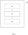
- Fig. 6 is a schematic illustration of an example of an apparatus 600.
- the apparatus 600 may be used to perform the methods disclosed herein.
- the apparatus 600 comprises a processor 602 configured to perform steps of the methods 200, 400 disclosed herein.
- the apparatus 600 may be a computing device, such as a workstation, a desktop computer, a laptop computer, a tablet computer, a smart phone or a wearable device, or the apparatus may comprise a device forming part of a cloud-computing environment, such as a server.
- the apparatus 600 may further comprise a display 604.
- the display 604 may be configured to display a representation of at least part of the anatomical structure, an indication of the first point of the second plurality or points relative to the anatomical structure and the corresponding point of the first plurality of points relative to the first point and to the anatomical structure.
- the display 604 may, for example, be configured to display images similar to those shown in Fig. 5 .
- the apparatus 600 may, in some embodiments, further comprise a user interface 606.
- the user interface 606 may be configured to enable a user to modify at least one of: a relative angular position of the first point of the second plurality around the position of its corresponding point of the first plurality; a position of one or more points of the first plurality of points; and a position of one or more points of the second plurality of points. Modifying the position of one or more points using the user interface may be achieved in the manner disclosed herein.
- Fig. 7 is a schematic illustration of an example of a processor 702 in communication with a computer-readable medium 704.
- the processor 702 may comprise or be similar to the processor 602 discussed above.
- a computer program product comprises a non-transitory computer-readable medium 704, the computer-readable medium having computer-readable code embodied therein, the computer-readable code being configured such that, on execution by a suitable computer or processor 702, the computer or processor is caused to perform steps of the methods 200, 400 disclosed herein.
- embodiments disclosed herein provide a mechanism by which a reference model 106 can be manipulated by a user (e.g., to fit a particular part of anatomical structure) while maintaining a particular distance or position relative to anatomical model 104.
- a reference model 106 can be manipulated by a user (e.g., to fit a particular part of anatomical structure) while maintaining a particular distance or position relative to anatomical model 104.
- the processor 602, 702 can comprise one or more processors, processing units, multicore processors or modules that are configured or programmed to control the apparatus 600 in the manner described herein.
- the processor 602, 702 can comprise a plurality of software and/or hardware modules that are each configured to perform, or are for performing, individual or multiple steps of the method described herein.
- module is intended to include a hardware component, such as a processor or a component of a processor configured to perform a particular function, or a software component, such as a set of instruction data that has a particular function when executed by a processor.
- the sub-routines may be stored together in one executable file to form a self-contained program.
- Such an executable file may comprise computer-executable instructions, for example, processor instructions and/or interpreter instructions (e.g., Java interpreter instructions).
- one or more or all of the sub-routines may be stored in at least one external library file and linked with a main program either statically or dynamically, e.g., at run-time.
- the main program contains at least one call to at least one of the sub-routines.
- the sub-routines may also comprise function calls to each other.
- An embodiment relating to a computer program product comprises computer-executable instructions corresponding to each processing stage of at least one of the methods set forth herein.
- a computer program may be stored or distributed on a suitable medium, such as an optical storage medium or a solid-state medium supplied together with or as part of other hardware, but may also be distributed in other forms, such as via the Internet or other wired or wireless telecommunication systems. Any reference signs in the claims should not be construed as limiting the scope.
Landscapes
- Engineering & Computer Science (AREA)
- Architecture (AREA)
- Computer Graphics (AREA)
- Computer Hardware Design (AREA)
- General Engineering & Computer Science (AREA)
- Software Systems (AREA)
- Physics & Mathematics (AREA)
- General Physics & Mathematics (AREA)
- Theoretical Computer Science (AREA)
- Apparatus For Radiation Diagnosis (AREA)
Priority Applications (2)
| Application Number | Priority Date | Filing Date | Title |
|---|---|---|---|
| EP23214153.1A EP4567740A1 (fr) | 2023-12-05 | 2023-12-05 | Modification d'un modèle associé à des structures anatomiques |
| PCT/EP2024/083507 WO2025119698A1 (fr) | 2023-12-05 | 2024-11-26 | Modification d'un modèle associé à des structures anatomiques |
Applications Claiming Priority (1)
| Application Number | Priority Date | Filing Date | Title |
|---|---|---|---|
| EP23214153.1A EP4567740A1 (fr) | 2023-12-05 | 2023-12-05 | Modification d'un modèle associé à des structures anatomiques |
Publications (1)
| Publication Number | Publication Date |
|---|---|
| EP4567740A1 true EP4567740A1 (fr) | 2025-06-11 |
Family
ID=89119315
Family Applications (1)
| Application Number | Title | Priority Date | Filing Date |
|---|---|---|---|
| EP23214153.1A Pending EP4567740A1 (fr) | 2023-12-05 | 2023-12-05 | Modification d'un modèle associé à des structures anatomiques |
Country Status (2)
| Country | Link |
|---|---|
| EP (1) | EP4567740A1 (fr) |
| WO (1) | WO2025119698A1 (fr) |
Citations (2)
| Publication number | Priority date | Publication date | Assignee | Title |
|---|---|---|---|---|
| US20150145857A1 (en) * | 2013-11-27 | 2015-05-28 | Disney Enterprises, Inc. | Contextual editing using variable offset surfaces |
| EP3629287A1 (fr) * | 2018-09-25 | 2020-04-01 | Laralab UG | Génération assistée ou automatique d'une structure de représentation numérique d'une structure annulaire d'une valve d'un organe interne humain |
-
2023
- 2023-12-05 EP EP23214153.1A patent/EP4567740A1/fr active Pending
-
2024
- 2024-11-26 WO PCT/EP2024/083507 patent/WO2025119698A1/fr active Pending
Patent Citations (2)
| Publication number | Priority date | Publication date | Assignee | Title |
|---|---|---|---|---|
| US20150145857A1 (en) * | 2013-11-27 | 2015-05-28 | Disney Enterprises, Inc. | Contextual editing using variable offset surfaces |
| EP3629287A1 (fr) * | 2018-09-25 | 2020-04-01 | Laralab UG | Génération assistée ou automatique d'une structure de représentation numérique d'une structure annulaire d'une valve d'un organe interne humain |
Non-Patent Citations (1)
| Title |
|---|
| SHINOTANAKA: "Tinkercad Blog: New feature: Smart duplicate", 8 August 2012 (2012-08-08), XP093168300, Retrieved from the Internet <URL:https://www.tinkercad.com/blog/new-feature-smart-duplicate> * |
Also Published As
| Publication number | Publication date |
|---|---|
| WO2025119698A1 (fr) | 2025-06-12 |
Similar Documents
| Publication | Publication Date | Title |
|---|---|---|
| US12076158B2 (en) | Intuitive display for rotator cuff tear diagnostics | |
| US11328812B2 (en) | Medical image processing apparatus, medical image processing method, and storage medium | |
| EP3382642B1 (fr) | Système d'annotation et de segmentation hautement intégré pour imagerie médicale | |
| US11127138B2 (en) | Automatic detection and quantification of the aorta from medical images | |
| US11158046B2 (en) | Estimating measurements of craniofacial structures in dental radiographs | |
| US10800550B2 (en) | Positioning enhancements to localization process for three-dimensional visualization | |
| US11337669B2 (en) | Automatic positioning of an X-ray source by way of segmentation | |
| JP2019121283A (ja) | 予測モデル生成システム及び予測システム | |
| CN111063422A (zh) | 一种医学图像标注方法、装置、设备及介质 | |
| US11099724B2 (en) | Context sensitive magnifying glass | |
| de Almeida et al. | A neuronavigation system using a mobile augmented reality solution | |
| EP4567740A1 (fr) | Modification d'un modèle associé à des structures anatomiques | |
| US12293524B2 (en) | Predicting correctness of algorithmic segmentation | |
| CN1961335A (zh) | 用于对图像上的对象进行缩放的图像处理设备、成像系统、计算机程序、和方法 | |
| JP7296941B2 (ja) | 医療画像の表示 | |
| US11553891B2 (en) | Automatic radiography exposure control using rapid probe exposure and learned scene analysis | |
| CN1961340B (zh) | 用于图像处理的方法、计算机程序、设备和成像系统 | |
| CN107106106B (zh) | 针对具有减小的角范围的旋转c型臂计算机断层摄影的自适应分割 | |
| JP6110342B2 (ja) | 放射線量管理装置、放射線量管理方法および放射線量管理プログラム | |
| KR20140015079A (ko) | 중심선을 보정하는 방법 및 장치 | |
| JP6263653B2 (ja) | 放射線量管理装置、放射線量管理方法および放射線量管理プログラム | |
| US12232900B2 (en) | Interactive contour refinements for data annotation | |
| KR102945001B1 (ko) | 다시점 측정데이터 조합을 통한 데이터 추정 및 그 가시화 방법 | |
| CN116490884A (zh) | 医学图像处理方法、设备及放疗系统 | |
| KR102745947B1 (ko) | 환자에 대한 치료 스케줄을 디스플레이하는 방법, 디바이스 및 그 기록매체 |
Legal Events
| Date | Code | Title | Description |
|---|---|---|---|
| PUAI | Public reference made under article 153(3) epc to a published international application that has entered the european phase |
Free format text: ORIGINAL CODE: 0009012 |
|
| STAA | Information on the status of an ep patent application or granted ep patent |
Free format text: STATUS: THE APPLICATION HAS BEEN PUBLISHED |
|
| AK | Designated contracting states |
Kind code of ref document: A1 Designated state(s): AL AT BE BG CH CY CZ DE DK EE ES FI FR GB GR HR HU IE IS IT LI LT LU LV MC ME MK MT NL NO PL PT RO RS SE SI SK SM TR |
|
| STAA | Information on the status of an ep patent application or granted ep patent |
Free format text: STATUS: THE APPLICATION IS DEEMED TO BE WITHDRAWN |