EP4567759A1 - Behälterrücknahmesystem mit bidirektionalem förderer - Google Patents
Behälterrücknahmesystem mit bidirektionalem förderer Download PDFInfo
- Publication number
- EP4567759A1 EP4567759A1 EP23214402.2A EP23214402A EP4567759A1 EP 4567759 A1 EP4567759 A1 EP 4567759A1 EP 23214402 A EP23214402 A EP 23214402A EP 4567759 A1 EP4567759 A1 EP 4567759A1
- Authority
- EP
- European Patent Office
- Prior art keywords
- flight
- conveyor
- return
- containers
- container
- Prior art date
- Legal status (The legal status is an assumption and is not a legal conclusion. Google has not performed a legal analysis and makes no representation as to the accuracy of the status listed.)
- Pending
Links
Images






Classifications
-
- G—PHYSICS
- G07—CHECKING-DEVICES
- G07F—COIN-FREED OR LIKE APPARATUS
- G07F7/00—Mechanisms actuated by objects other than coins to free or to actuate vending, hiring, coin or paper currency dispensing or refunding apparatus
- G07F7/06—Mechanisms actuated by objects other than coins to free or to actuate vending, hiring, coin or paper currency dispensing or refunding apparatus by returnable containers, i.e. reverse vending systems in which a user is rewarded for returning a container that serves as a token of value, e.g. bottles
- G07F7/0609—Mechanisms actuated by objects other than coins to free or to actuate vending, hiring, coin or paper currency dispensing or refunding apparatus by returnable containers, i.e. reverse vending systems in which a user is rewarded for returning a container that serves as a token of value, e.g. bottles by fluid containers, e.g. bottles, cups, gas containers
-
- B—PERFORMING OPERATIONS; TRANSPORTING
- B07—SEPARATING SOLIDS FROM SOLIDS; SORTING
- B07C—POSTAL SORTING; SORTING INDIVIDUAL ARTICLES, OR BULK MATERIAL FIT TO BE SORTED PIECE-MEAL, e.g. BY PICKING
- B07C5/00—Sorting according to a characteristic or feature of the articles or material being sorted, e.g. by control effected by devices which detect or measure such characteristic or feature; Sorting by manually actuated devices, e.g. switches
- B07C5/36—Sorting apparatus characterised by the means used for distribution
-
- B—PERFORMING OPERATIONS; TRANSPORTING
- B65—CONVEYING; PACKING; STORING; HANDLING THIN OR FILAMENTARY MATERIAL
- B65G—TRANSPORT OR STORAGE DEVICES, e.g. CONVEYORS FOR LOADING OR TIPPING, SHOP CONVEYOR SYSTEMS OR PNEUMATIC TUBE CONVEYORS
- B65G47/00—Article or material-handling devices associated with conveyors; Methods employing such devices
- B65G47/02—Devices for feeding articles or materials to conveyors
- B65G47/04—Devices for feeding articles or materials to conveyors for feeding articles
- B65G47/12—Devices for feeding articles or materials to conveyors for feeding articles from disorderly-arranged article piles or from loose assemblages of articles
- B65G47/14—Devices for feeding articles or materials to conveyors for feeding articles from disorderly-arranged article piles or from loose assemblages of articles arranging or orientating the articles by mechanical or pneumatic means during feeding
- B65G47/1407—Devices for feeding articles or materials to conveyors for feeding articles from disorderly-arranged article piles or from loose assemblages of articles arranging or orientating the articles by mechanical or pneumatic means during feeding the articles being fed from a container, e.g. a bowl
- B65G47/1442—Devices for feeding articles or materials to conveyors for feeding articles from disorderly-arranged article piles or from loose assemblages of articles arranging or orientating the articles by mechanical or pneumatic means during feeding the articles being fed from a container, e.g. a bowl by means of movement of the bottom or a part of the wall of the container
- B65G47/1471—Movement in one direction, substantially outwards
-
- G—PHYSICS
- G07—CHECKING-DEVICES
- G07F—COIN-FREED OR LIKE APPARATUS
- G07F11/00—Coin-freed apparatus for dispensing, or the like, discrete articles
- G07F11/02—Coin-freed apparatus for dispensing, or the like, discrete articles from non-movable magazines
- G07F11/04—Coin-freed apparatus for dispensing, or the like, discrete articles from non-movable magazines in which magazines the articles are stored one vertically above the other
- G07F11/16—Delivery means
- G07F11/26—Endless bands
-
- B—PERFORMING OPERATIONS; TRANSPORTING
- B65—CONVEYING; PACKING; STORING; HANDLING THIN OR FILAMENTARY MATERIAL
- B65G—TRANSPORT OR STORAGE DEVICES, e.g. CONVEYORS FOR LOADING OR TIPPING, SHOP CONVEYOR SYSTEMS OR PNEUMATIC TUBE CONVEYORS
- B65G15/00—Conveyors having endless load-conveying surfaces, i.e. belts and like continuous members, to which tractive effort is transmitted by means other than endless driving elements of similar configuration
- B65G15/30—Belts or like endless load-carriers
- B65G15/32—Belts or like endless load-carriers made of rubber or plastics
- B65G15/42—Belts or like endless load-carriers made of rubber or plastics having ribs, ridges, or other surface projections
-
- B—PERFORMING OPERATIONS; TRANSPORTING
- B65—CONVEYING; PACKING; STORING; HANDLING THIN OR FILAMENTARY MATERIAL
- B65G—TRANSPORT OR STORAGE DEVICES, e.g. CONVEYORS FOR LOADING OR TIPPING, SHOP CONVEYOR SYSTEMS OR PNEUMATIC TUBE CONVEYORS
- B65G17/00—Conveyors having an endless traction element, e.g. a chain, transmitting movement to a continuous or substantially-continuous load-carrying surface or to a series of individual load-carriers; Endless-chain conveyors in which the chains form the load-carrying surface
- B65G17/06—Conveyors having an endless traction element, e.g. a chain, transmitting movement to a continuous or substantially-continuous load-carrying surface or to a series of individual load-carriers; Endless-chain conveyors in which the chains form the load-carrying surface having a load-carrying surface formed by a series of interconnected, e.g. longitudinal, links, plates, or platforms
- B65G17/08—Conveyors having an endless traction element, e.g. a chain, transmitting movement to a continuous or substantially-continuous load-carrying surface or to a series of individual load-carriers; Endless-chain conveyors in which the chains form the load-carrying surface having a load-carrying surface formed by a series of interconnected, e.g. longitudinal, links, plates, or platforms the surface being formed by the traction element
-
- B—PERFORMING OPERATIONS; TRANSPORTING
- B65—CONVEYING; PACKING; STORING; HANDLING THIN OR FILAMENTARY MATERIAL
- B65G—TRANSPORT OR STORAGE DEVICES, e.g. CONVEYORS FOR LOADING OR TIPPING, SHOP CONVEYOR SYSTEMS OR PNEUMATIC TUBE CONVEYORS
- B65G2201/00—Indexing codes relating to handling devices, e.g. conveyors, characterised by the type of product or load being conveyed or handled
- B65G2201/02—Articles
- B65G2201/0235—Containers
- B65G2201/0244—Bottles
Definitions
- the present inventive concept relates to a method and a system for receiving a bulk of used deposit return containers for recycling or reuse.
- a system comprising a conveyor for transporting deposit return containers from an infeed region towards a classification unit, where containers classified as not-accepted are returned to a user.
- Devices for receiving, identifying and/or sorting objects may be used in reverse vending machines in e.g. super markets. Many times, these devices receive the containers one by one, and a user therefore must feed the containers one by one to the device. Many times, containers fed to the devices are returned to the user when the machine has classified the container as not accepted. This can be a time consuming effort for the user.
- container return systems configured to receive a bulk of containers. Such container return systems often comprises classification units to determine which containers are to be accepted and which are to be returned to the user. However, there is a need for improvement of the bulk feed sorting as well as improved return of containers classified as not accepted.
- a container return system configured to receive a bulk of deposit return containers such as used food or beverage containers through an infeed opening.
- the container return system comprising:
- a container return system may be any system adapted to collect, sort, crush, compact and/or convey used deposit return containers for recycling or reuse, including used food or beverage containers, such as empty beverage bottles and cans, or glasses and/or cups such as coffee cups, of any size and material, such as PET, aluminum, tin, or glass.
- a deposit return container may be a container which upon its return is eligible for a refund such as a "pfand" from the Deutsche Pfandsystem GmbH (DPG).
- DPG Deutsche Pfandsystem GmbH
- Such a system may be used by professional operators, for example in recycling centers collecting used beverage containers from the restaurant industry.
- An example of such a system is the device for singulation of used beverage containers received in bulk described in EP 3481753A1 .
- a container return system may also be a reverse vending machine (RVM) located, for example, in a supermarket, where an end-consumer feeds used food and beverage containers into the container return system.
- RVM reverse vending machine
- a container return system typically, only the front of the container return system, including the infeed area, is visible and accessible to the end-consumer, with a backroom facility only accessible to store employees or other authorized personnel.
- used container should be interpreted as empty container, e.g. after (most of) the contents of the container has been drunk, eaten, disposed of or otherwise used. Sometimes the used container is completely empty when fed into the container return system, sometimes it is not, but contains some liquid and/or amount of the previous content. Many times the container content has been e.g. poured out and only some residues remain which was not easily poured out at the time.
- a container return system as described herein may also be used to receive other types of recyclable or reusable containers.
- a container return system according to the present inventive concept may be configured to receive used containers for cosmetics such as shampoo bottles and/or, paint, and/or chemicals, and/or any other type of consumer or professional product.
- the container return system may be adapted to handle all or some of the different standard sizes of containers in different countries; and preferably configured to only handle a predetermined list of containers, if other containers are entered they will after inspection preferably be treated as an foreign object. It may e.g. be able to handle a mix of 33 cl and 50 cl aluminum cans, as well as 33 cl, 50 cl and 1.5 L PET bottles.
- the container return system is adapted or configured to handle a certain type of container
- the container return system is adapted or configured to receive, transport and process this certain type of container. It is understood that a container return system which handles a certain type of container is adapted or configured to receive, transport and process this certain type of container.
- the diameter, or length, of the used containers received and transported by the container return system is at least 20 mm or at least 50 mm, and/or at most 150 mm, or at most 200 mm, or at most 350 mm. Additionally or alternatively, the height (i.e. the longest side) of the containers received and transported by the container return system is at least 50 mm, or at least 75 mm and/or at most 200 mm, or at most 380 mm, or at most 500 mm. Additionally or alternatively, the weight of the used containers that are received and transported by the container return system is at least 10 g, and/or at most 3 kg, or at most 5 kg. Additionally or alternatively, the volume of the used containers that are received and transported by the container return system is at least 10 ml, or at least 50 ml, and/or at most 3 L, or at most 5 L, or at most 8 L.
- the height (i.e. the longest side) of the smallest used container handled by the return system is smaller than the diameter of the largest used container handled by the container return system.
- the used containers classified as accepted by the classification unit may be transported to storage containers.
- the used containers classified as accepted by the classification unit may be transported to different storage containers depending on the material and/or type of the used containers.
- the used containers may be devaluated before being transported to storage containers.
- the used containers may be compacted and/or crushed before being transported to storage containers.
- a container return system according to the first, second or third aspect may optionally comprise devaluation means for devaluating used containers.
- the conveying part of the conveyor may e.g. be formed of a belt, e.g. a continuous reinforced textile belt or a modular belt.
- a modular belt comprises individual modules, also referred to as belt pieces, which are linked together e.g. with joint rods.
- the modular belt is optionally made of plastic and may be driven by chain sprockets, and the base frame of the conveyor may be constructed on standard profile supports.
- the individual modules may all have the same shape and surface area, or the modular belt may be formed of individual modules having e.g. 2 or 3 or at least 4 different designs. According to one example all designs have the same length, according to an alternative example, at least one design has a length which is different from the length of the other designs. According to yet another example each design has a unique length. Optionally, each design has a unique width, or at least one design has a different width compared to the other designs.
- RVM Reliable and Low-power mobile device
- a Container return system relating e.g. to transportation speed, accuracy of verification, batch size (number of returnable objects that may be accepted in per filling) ,throughput (process time per batch), long term throughput (number of processed batches over time).
- the invention is based on an insight that by a combination cleverly selected features the inventors have managed to enable an increase of both the accuracy and the throughput, and often also the long term through put, without compromising the user safety; in more detail, what the inventors have provided is a bi-directional conveyor with small collapsable flights of having a specific and smooth geometry.
- a wedge shape of the flight allows for a pivotable movement to be applied in elevating and collapsing the flights which can facilitate the elevation of the flight.
- the flight being elevated along a portion of the conveyor allows for the solution of an efficient transportation of containers in a dual direction, as well as providing a safe area being the access region for accessing the not accepted containers.
- Deposit return containers are often empty containers having a low weight, which have a probability of getting stuck on the conveyor. For example, aluminum or plastic cans or bottles have truly little weight.
- the conveyor is transporting the containers, such containers may enter a free spin mode or an endless spin where they just spin around, and do not follow the transportation direction.
- the transporting surface can be formed in various ways, it may e.g. be a the upper part of a modular belt formed e.g. belt pieces made of plastic.
- the diverter may have a shape and form so that the diverter can be adapted to deflect the containers to a side of the conveyor towards a classification unit.
- the diverter may be arranges such that when a container reaches the diverter, the intersection of the container and the diverter changes the direction of the container to the side of the conveyor.
- the non-accepted containers can be returned to the access area.
- the diver In the Return mode, the diver is in a non-diverting position allowing for container to be transported from the remote region to the access region. The flights will perform a similar action in the return mode, disturbing the containers and preventing containers from getting stuck on the conveyor.
- the flight is provided with an acute angle between the transporting surface and the top surface of the flight at the low end.
- the angle of the flight at the low end in the return mode is such that if there is a minor error in the flight not collapsing in the safe access area, the flight preferably collapses upon a user lightly pressing the flight. Hence, the angle allows for the user to access the area of not accepted containers without risk of harming fingers.
- Overall a container return system is provided having improved safety measures for a user.
- each flight comprises a recess configured such that the flight can be attached to the conveyor via a snap attachment.
- a configuration facilitates the removal and later attachment of flights to the conveyor e.g. for cleaning purposes.
- the flight comprises more than one recess.
- a flight can be attached to a variety of conveyors not limiting the use of the flight.
- a further advantage presented by the snap function is that the conveyor does not need to be dismantled in order to attach the flight, but the flight may be attached in a space previously occupied by a belt portion, e.g. a belt piece when a modular belt is used.
- the conveyor comprises a plurality of flights arranged in a zig zag pattern along the conveyor in the infeed direction.
- a zig zag pattern may provide an improved even flow of container along the conveyor.
- the flights may reach any container along the conveyor. This is advantageous since it reduces the risk of containers getting stuck or jammed on the conveyor.
- the deposit return containers have a predetermined minimum height and minimum width
- said conveyor return system further comprises two side rails 130, each rail being arranged on a respective distal side of the transporting surface in the infeed direction, and at least one wedge shaped flight is attached to the conveyor at a distance from one of said side rails 130, which distance is less than the minimum height.
- the flight has a rounded top portion. Additionally or alternatively, the top surface is substantially flat and/or curved. According to some examples the top surface is curved along one axis or two axes.
- the transporting surface or the modular belt may have a cut out configured to allow the flight to be raised above the transporting surface. It is beneficial to have the cut out sized such that there is a limited gap or play between the flight and the transporting surface. If the gap is too large, this may cause a container to get jammed or stuck therein.
- a flight with a rounded top portion, and/or wherein the top surface is substantially flat and/or curved may provide an advantage since the cut out in the transporting surface can be configured such that there is a reduced or no gap between the flight and the transporting surface in the collapsed and/or elevated position.
- the lower part of said high end is substantially vertical.
- the flight in an event of a flight being in the upraised position in the access region, the flight is configured to return to the collapsed position upon reaching a stationary finger and the transporting surface is moving in the return direction.
- the transporting surface is moving in the return direction.
- the transporting surface and/or each flight is made of polymeric material, e.g. a plastic..
- the container return system further comprises a slide or chute configured for transporting the deposit return containers from said infeed opening to said infeed region.
- the chute may be arranged and/or extend a distance between the infeed opening and the infeed region.
- the infeed region and the access region are at least partially overlapping. In some examples the infeed region and the access region are separated areas. In some examples, the infeed region and the access region completely overlap.
- the container return system does not comprise a diverter.
- the containers may be guided towards the classification unit which may be at or after the remote end of the bi-directional conveyor.
- the classification unit is located above or below the conveyor.
- a flight configured to be attached to a bi-directional conveyor.
- the flight may comprise a recess for a snap in attachment.
- the flight may have a wedge shape as seen from the surface of the bi-directional conveyor.
- the conveyor may optionally be formed or made by several belt pieces connected and intertwined similarly to a puzzle.
- the conveyor may be a modular belt.
- the modular belt, the joint rod or the belt pieces may comprise a rod or pin whereto a flight may be attached by a snap function.
- the flight may be configured such that the recess is adapted to fit into structure of the conveyor in place of a belt piece, thereby allowing for the snap function and hence a facilitated attachment of the flight; which may eliminate or reduce the need to disassemble an already set up conveyor.
- a further advantage is that the flight can be attached to already in use bi-directional conveyors, e.g. to improve efficiency of the bi-directional conveyor by reducing the risk of objects getting stuck on bi-directional conveyors.
- a container return system comprising a bi-directional conveyor, at least one flight, an elevation member and a retention member.
- the elevation and/or retention and/or lowering of the flight may be achieved e.g. by a sliding action or a cam action, or an actuator or a parallel lifting; each of these means may be arranged beneath the transporting surface of the conveyor.
- the present container return system is configured to receive a bulk of deposit return containers, such as used food or beverage containers through an infeed opening.
- the container return system comprises a classification unit which is configured to classify a deposit return container as accepted or not accepted.
- the classification unit may have other classifiers beyond accepted and not accepted. If accepted, the deposit return container may have a crusher for crushing the deposit return container, or other suitable means for handling the accepted container. If the deposit return container is determined to be not accepted, the deposit return containers is to be returned to the user.
- the returned deposit return containers can be accessed by a user through the same infeed opening as is used to enter deposit return containers into the container return system.
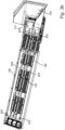
- Fig. 1 shows a perspective view of an example of a bi-directional conveyor 102, for a container return system.
- the container return system is configured to receive a bulk of used deposit return containers or used containers through an infeed region 110.
- the two directions of the bi-directional conveyor 102 are an infeed direction ID and a return direction RD.
- the conveyor is straight.
- the infeed direction ID and the return direction RD are as seen from above the conveyor, in the transport directions. It should however be comprehended that the conveyor does not need to be straight, but can have different shapes, such as a curve or s-shape, or any other shape.
- the bi-directional conveyor 102 has a front end 104, and a remote end 106.
- a transporting surface 108 extends between the front end 104 and the remote end 106.
- the container return system may comprise a chute or slide 119 via which deposit return containers can reach the bi-directional conveyor 102.
- the chute 119 may facilitate the loading of the bulk containers into the container return system.
- the chute 119 may provide a distance between the infeed opening of the container return system and the infeed region 110 of the bi-directional conveyor. Meaning, for example, that the user can enter the deposit return containers at the infeed opening, whereafter the containers are transported to the infeed region 110 via the chute 119.
- the bi-directional conveyor 102 is designed to transport deposit return containers in the infeed direction ID when the system is in the receive mode. Deposit return containers are transported from the infeed region 110 towards the classification by moving the transporting surface in the infeed direction ID.
- the bi-directional conveyor 102 is designed to transport deposit return containers in the return direction RD when the system is in the return mode.
- the bi-directional conveyor 102 moving the transport surface 108 in the return direction RD.
- the infeed direction ID and the return direction RD are opposite directions to one another.
- the containers When deposit return containers reach the conveyor, the containers land on the transporting surface 108 at the front end 104 of the bi-directional conveyor 102. At the front end 104 there is an infeed region 110 symbolizing where the deposit return containers may enter the conveyor.
- the bi-directional conveyor 102 is configured to run in the return direction RD during the return mode, when the not accepted deposit return containers are returned. To return containers, the deposit return containers are transported from the remote region 114 to an access region 112 by moving the transporting surface 102 in the return direction RD.
- the access region 112 is arranged about the front end 104 of the bi-directional conveyor 102. A user can access the returned containers at the access region 112.
- the access region 112 may partially overlap with the infeed region 110. In some examples, the infeed region 100, and the access region 112 are completely overlapping.
- the access region 112 provides the system with a region in which the user can place their hands in order to retrieve containers in a safe manner.
- a remote region 114 is arranged closer to the remote end 106 when compared to the access region 112 and the infeed region 110.
- the bi-directional conveyor 102 comprises a diverter 116.
- the diverter 116 is positioned in a diverting position across the conveyor.
- the angle may be 45 degrees to the conveyor or any suitable angle.
- the diverter in some examples forces the containers that are transported on the conveyor to a side thereof. After leaving the bi-directional conveyor the deposit return containers can be transported to the classification unit.
- the diverter 116 may be movable between the diverting position and the non-diverting position.
- the diverter 116 may be pivotably movable. In some examples the diverter 116 is lifted and turned to swap positions.
- the diverter 116 may be movable or fixed.
- the diverter 116 is in the diverting position during the receive mode, and in the non-diverting position in the return mode.
- the container return system does not comprise a diverter 116.
- the classification unit may for example be located beyond the remote end 106.
- a transportation means may be located at the remote end 106 for transporting the deposit return container to the classification unit.
- the classification unit may be located at a suitable place to improve efficiency of the system.
- the bi-directional conveyor 102 comprises at least one flight 120.
- the bi-directional conveyor may comprise a plurality of flights 120.
- the flights 120 may be arranged on the conveyor along two lines. In some examples the flights 120 are arranged in a zig zag pattern.
- the flights are preferably arranged such as to avoid being in the same line as the gears 117 that drives the conveyor. There are no limitations to how the flights 120 can be arranged on the conveyor.
- Fig. 2a An example of a flight is shown in Fig. 2a .
- the flight shown has a wedge shape. It should be noted that other shapes of the flight may be possible and have advantages.
- Figs. 2b and 2c shows the flight from different angles.
- the flight 120 may have the wedge shape at least as seen/measured from the transporting surface 108 of the conveyor when the flight is in its elevated position.
- the wedge shaped flight 120 has a low end 122, a high end 124, a top surface 126 and a bottom surface 128.
- the flight 120 is or is configured to be pivotably attached to the bi-directional conveyor 102 and pivotable between a collapsed position and an elevated position by means of e.g. a slide or ramp.
- the flight may have other means for enabling movement between the collapse and elevated position. For example, by an actuator, or a camming, or a parallel lifting.
- the flight 120 extends higher above the transporting surface 108 when it is in the elevated position compared to when it is in the collapsed position.
- one or both of the recesses 121,123 controls the position of the flight when in the collapsed position.
- the bottom surface 128 may be substantially in the same plane as the transporting surface 108 when the flight is in the elevated position.
- the high end 124 and the top surface 126 meet at the highest port of the flight 120.
- the high end 124 of the wedge shaped flight trails the low end 122 of the wedge shaped flight when the transporting surface moves in the return direction.
- the top surface 126 slopes downwards as seen in the return direction.
- the top surface 126 may be straight but may in other examples be curved, concave or have another shape.
- the top surface is preferably configured as a surface that would not harm a user if their finger slides along the flight in a direction opposite to the return direction.
- the high end 124 slopes upwards as seen in the return direction.
- an upper third of the high end 124 may slope upwards, or at least half of the high end 124 may slope upwards.
- the lower part of the high end 124 may be substantially vertical above the transporting surface. This may aid in the interference with the containers.
- the high end is vertical, when the flight is in the elevated position.
- the distance between the highest point of the flight 120 is optionally less than a distance D between the transporting surface 108 and the diverter. This allows the flights 120 of the conveyor to pass under the diverter 116, in both directions.
- the flight 120 is thus optionally arranged to be able to pass under the diverter 116, but should still have a height sufficient to interact with the return deposit containers.
- the height of the flight 120 may be within a range of 8-25mm.
- the height is adapted to force cylidrical or substantially cylindrical containers out of a stationary rolling state.A height of 8 mm up to 15 mm is many times sufficient.
- the height is within a range of 10-12mm. In some examples, the height is within a range of 8-12mm.
- the height of the flights 120 may be below 8mm in some examples. In some examples, the height may be above 15mm. In some examples, the height may be within a range of 8-15mm. In a larger application, the height may be above 25mm.
- the inventors have seen that a flight having a hight with the range of 8-25 is very effective in getting a container out of an stationary rolling state; the higher the flight the more effective it is at solving blockage, while a lower height is advantageous as it provides a smaller flight extension when the transportation surface is facing downwards, especially as there might be some slack in the conveyor belt.
- the height of the flight 120 is thus correlated to the container received in the container return system.
- the container return system is configured for, such as cans, bottles, cartons, or any other packages, the height of the flight will be able to interact with the container and travel under the diverter 116.
- the flights 120 are preferably configured and shaped such that any container directly between the diverter 116 and the flight 120 will roll over the flight 120, for example by making the high end slope upwards in the intended return direction.
- the transporting surface 108 may comprise a cut out or opening for the flight through which the flight may protrude. It is preferred that the gap between the elevated flight 120 and the adjacent conveyor surface is at most 5 mm, so as to reduce the risk of containers getting stuck in the gap.
- the gap may be 1mm in a preferred example. In other examples, the gap may be 0.3-5mm.
- the high end 124 of the flight is in a preferred example rounded. A rounded high end 124 may minimize the gap formed, between the transporting surface and the high end, when raising and collapsing the flight 120.
- a gap in the collapsed position may provide a pinch hazard in the access region 112 and is thus preferably filled with the collapsed flight.
- the deposit containers transported on the conveyor are often light weight and optionally cylinder shaped or substantially cylinder shaped.
- a (substantially) cylinder shaped container has a (substantially) round cross-section along a portion or a major extension of its length.
- the center axis or length axis of the container intersects with both the top and bottom of the contianer Many times the container spin in a backwards direction
- the flights 120 as described herein may prevent that containers end up in an endless spin by interfering with the containers on the conveyor. Such an interference is advantageous as it may e.g. push the container out of the stationary rolling state.
- the high end 124 of the flight may have a rounded top.
- the flight 120 may have a rounded bottom at the high end 124 of the wedge shape.
- the rounded surfaces may aid when a container ends up between the diverter 116 and the flight 120 such that the container can more easily roll over the top surface, than if the top was arranged as a sharp edge.
- the top portion of the flight 120 may be substantially flat.
- the top portion of the flight 120 may be curved.
- top surface 126 may be rounded, and/or curved along one or two perpendicular axis. In other implementations the top surface 126 may be chamfered.
- a shower door is normally flat, or curved along only one axis.
- a bowl is curved along two orthogonal axis (both along a horizontal line, as well as along a vertical line.)
- the flight 120 may comprise a recess 121 which enables the flight 120 to move between the collapsed and elevated position.
- the recess 121 can be a closed hole in some examples.
- the flight 120 may comprise a second recess 123 at the low end 122 of the flight 120.
- the second recess 123 can be a closed hole in some examples. Implementations where the flight 120 comprises the recess 121 and the second recess 123 can enable attachment of the flight 120 to the conveyor via a snap function.
- the flight 120 can thus be attached by a small push force. This allows for a facilitated upgrade of already assembled container return systems. There is no need to disassemble a container return system or a conveyor in order to attach the flight 120.
- FIG. 3a and 3b showing a top view of the bi-directional conveyor 102.
- the system comprises at least one pair of elevation member 202 and a retention member 204.
- the elevation members 202 causes the flight 120 to go from the collapsed position to the elevated position.
- the elevation member 202 is arranged beneath the transporting surface 108 and advances gradually closer to said transporting surface 108 along the infeed direction ID.
- a retention member 204 is arranged under then transporting surface 108 after the elevation member 202 in the infeed direction ID.
- the system comprises a pair of elevations members allowing the flights to be raised to the elevated position when the conveyor moves in the return direction RD.
- the elevation members 202 may force the flight 120 to pivot around an axis at the low end 122 and thereby raise the flight 120 into the elevated position.
- Many options are possible for embodying the elevation members 202 in order to move the flight 120 from the collapsed position to the elevated position.
- the flight 120 may be elevated via a camming mechanism.
- the flights 120 may be parallel lifted in order to be elevated.
- Some arrangement may comprise floating means for raising the flight 120, or any means for pushing.
- a camming mechanism may further aid the flight 120 when it is supposed to collapse into the collapsed position.
- the elevation members 202 are located at a distance from the end of the conveyor for providing the access region 112.
- the bi-directional conveyor is configured such that all flights 120 are in the collapsed position in the access region 112. It is preferred that the flight collapses under the act of gravity before reaching the access region 112, however, if this is not the case due to one reason or another because there is no retention member 202 or elevation member 204 in the access region 112, if a flight 120 has not collapsed a touch or light press to the flight 120 in the access region 112 will push the flight 120 into the collapsed position.
- the flight is thus preferably configured to collapse upon reaching a stationary finger when the transporting surface 108 is moving in the return direction RD.
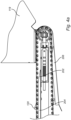
- Fig 4a is a closeup side view of the front end 104 of the bi-directional conveyor 102.
- the elevation member 202 can have the shape of a ramp gradually advancing closer to the transporting surface 108, and thereby, when the flight abuts the ramp, the flight 120 can pivot gradually and reach the elevated position.
- the retention member 204 may be an extension of the elevation member 202.
- the retention member 204 may be a separate unit from the elevation member 202.
- a front ramp 206 extending under the bi-direction conveyor 102 at the front end 104.
- the front ramp 206 forces the flight 120 to be in the collapsed position when the flight 120 pass over the edge at the front end 104, when the conveyor is in the receive mode and the conveyor is moving in the infeed direction ID. Gravity may be keeping the flight extended in the elevated position when the flights 120 are on the underside of the bi-direction conveyor 102.
- the front ramp 206 that extends to the upper side of the conveyor, forces any elevation of the flights 120 to be fully collapsed when going around the edge of the conveyor.
- the system may comprise a rear ramp 302.
- This remote ramp 302 is shown in Fig. 5 .
- the remote ramp 302 may be located above the conveyor at the remote region 114.
- the remote ramp 306 is used to transport the containers that have been deemed not accepted by the classification unit back onto the bi-directional conveyor 102.
- Containers that are not accepted can in some examples be returned to the bi-directional conveyor 102 in both the receive mode and in the return mode.
- the remote ramp 302 is preferably arranged as a stop wall such that containers do not fall of the bi-directional conveyor 102. Thereby when the diverter 116 is in the diverting position, the not accepted items will stay in the region between the diverter and the remote ramp 302. Upon placing the diverter 116 in the non-diverting position, the containers will return to the access region 112.
- the diverter is preferably in the non-diverting position so that the containers can move freely towards the access region 112 and the infeed region 110.
- the container return system may comprise two side rails 130.
- the side rails 130 may be arranged on a respective side of the transporting surface of the conveyor.
- the side rails 130 may prevent containers from falling off the bi-directional conveyor 102.
- the container return system may be configured to receive a predetermined type of container.
- the deposit return container may have a predetermined minimum height and minimum width.
- At least one flight 120 may be arranged on the conveyor at a distance from said side rail being less than the minimum height of the deposit return container.
- the flight 120 and/or the transporting surface described herein may be made of any suitable material.
- suitable material for example, glass, metal, polymer, or plastic, or any suitable combination thereof.
- the container return system may comprise more than one bi-directional conveyor.
- a second bi-directional conveyor may in some examples be used to transport diverted containers towards a classification unit.
- the system comprises a bi-directional conveyor 102, and at least one flight, an elevation member and a retention member as described herein.
- the system may comprise a singulation unit located in proximity to the classification unit.
- the infeed region 110 and the access region 112 may be adjacent one another side by side at the front end.
- the container return system may thus comprise a separator after the infeed opening such that containers land on the infeed region of the bi-directional conveyor.
- the container return system may comprise a means for directing the returned deposit return containers to the side of the conveyor having the access region 112.
- the infeed region 110 and the access region do not overlap but are separate. All flights 120 are in the collapsed position in the access region.
- the infeed opening may thus comprise an access opening.
- the access opening may be arranged such as to prevent that the a user putting hands in the access opening does not reach the infeed region 110.
- the belt is a modular belt.
- the modular belt may provide the conveyor with flexibility in how the conveyor can be arranged, such as curved etc.
- the modular belt pieces may have different sizes.
- the length of the modular belt pieces, as seen along the transport direction, is the same for each belt piece for the whole belt.
- the width, being orthogonal to the length, may vary.
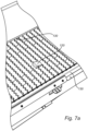
- This belt is made up of belt pieces of three different designs, all designs having the same length but different widths. All three designs are present on each row.
- the belt pieces may be arranged such that the flight 120 is attached between two belt pieces.
- Fig. 7b an example of the conveyor is shown , wherein the modular belt comprises a cut out for the flight 120.
- the flight 120 is shown in the elevated position.
- a gap 111a can be seen between the high end 120 side of the flight 120 and the belt piece.
- the high end 124 is curved, specifically when the curvature coincides with a pivot point of the flight 120, optionally gap 111a is consistent when the flight 120 is in the elevated and collapsed position. Thereby preventing pinching points.
- the size of the gap 111a may be substantially constant, while the flight 120 moves from the collapsed position, to the elevated position.
- Fig 7c show a top view of the flight 120 in the cut-out, wherein the flight is in a collapsed position.
- a gap 111b, 111c may be present on the sides of the flight 120. Such gap 111b, 111c may prevent the flight 120 from getting stuck in the elevated position, the collapsed position, or a position therebetween.
- the gap 111a, 111b, 111c is 1mm. in other examples the gap 111a, 111b, 111c may be 0,3-5mm. In some examples the gap has the same size on all sides of the flight 120.
Landscapes
- Physics & Mathematics (AREA)
- General Physics & Mathematics (AREA)
- Engineering & Computer Science (AREA)
- Mechanical Engineering (AREA)
- Branching, Merging, And Special Transfer Between Conveyors (AREA)
Priority Applications (1)
| Application Number | Priority Date | Filing Date | Title |
|---|---|---|---|
| EP23214402.2A EP4567759A1 (de) | 2023-12-05 | 2023-12-05 | Behälterrücknahmesystem mit bidirektionalem förderer |
Applications Claiming Priority (1)
| Application Number | Priority Date | Filing Date | Title |
|---|---|---|---|
| EP23214402.2A EP4567759A1 (de) | 2023-12-05 | 2023-12-05 | Behälterrücknahmesystem mit bidirektionalem förderer |
Publications (1)
| Publication Number | Publication Date |
|---|---|
| EP4567759A1 true EP4567759A1 (de) | 2025-06-11 |
Family
ID=89119456
Family Applications (1)
| Application Number | Title | Priority Date | Filing Date |
|---|---|---|---|
| EP23214402.2A Pending EP4567759A1 (de) | 2023-12-05 | 2023-12-05 | Behälterrücknahmesystem mit bidirektionalem förderer |
Country Status (1)
| Country | Link |
|---|---|
| EP (1) | EP4567759A1 (de) |
Citations (4)
| Publication number | Priority date | Publication date | Assignee | Title |
|---|---|---|---|---|
| EP1107194A1 (de) * | 1996-07-12 | 2001-06-13 | Tomra Systems ASA | Verfahren und Vorrichtung zum Prüfen von Flüssigkeitsbehälter |
| US20010017254A1 (en) * | 1998-03-20 | 2001-08-30 | Geus Jacob Frank De | Conveyor system for conveying and accumulating objects |
| EP3481753A1 (de) | 2016-07-06 | 2019-05-15 | Tomra Systems ASA | Vorrichtung und verfahren zur vereinzelung von gebrauchten getränke- oder lebensmittelbehältern |
| WO2020089436A1 (en) * | 2018-10-31 | 2020-05-07 | Tomra Systems Asa | Reverse vending machine arrangements and related methods |
-
2023
- 2023-12-05 EP EP23214402.2A patent/EP4567759A1/de active Pending
Patent Citations (5)
| Publication number | Priority date | Publication date | Assignee | Title |
|---|---|---|---|---|
| EP1107194A1 (de) * | 1996-07-12 | 2001-06-13 | Tomra Systems ASA | Verfahren und Vorrichtung zum Prüfen von Flüssigkeitsbehälter |
| US20010017254A1 (en) * | 1998-03-20 | 2001-08-30 | Geus Jacob Frank De | Conveyor system for conveying and accumulating objects |
| EP3481753A1 (de) | 2016-07-06 | 2019-05-15 | Tomra Systems ASA | Vorrichtung und verfahren zur vereinzelung von gebrauchten getränke- oder lebensmittelbehältern |
| EP3481753B1 (de) * | 2016-07-06 | 2020-11-04 | Tomra Systems ASA | Vorrichtung und verfahren zur vereinzelung von gebrauchten getränke- oder lebensmittelbehältern |
| WO2020089436A1 (en) * | 2018-10-31 | 2020-05-07 | Tomra Systems Asa | Reverse vending machine arrangements and related methods |
Similar Documents
| Publication | Publication Date | Title |
|---|---|---|
| CA3028869C (en) | Device and method for singulation of used beverage or food containers | |
| CA2792086C (en) | Package-culling conveyor system and method | |
| DE69734792T2 (de) | Vorrichtung und Verfahren zum Aufrichten, Festhalten und weiter Befördern einer Flasche | |
| US20040040822A1 (en) | Unit for automatic container returns systems | |
| CA2721141C (en) | An apparatus and method for feeding used objects | |
| US5988054A (en) | Automated system for handling returned drink containers | |
| CN111661371A (zh) | 一种多品种物料混合包装生产线和控制方法 | |
| US6736253B2 (en) | Apparatuses for the conveying, lifting and sorting of articles | |
| CA2146883C (en) | Apparatus for segregating and feeding fruit from a bulk supply | |
| EP0345036B1 (de) | Förderer mit Abgabevorrichtung | |
| DE202006013956U1 (de) | Warenannahmeautomat | |
| EP3340192A1 (de) | Verschliessbarer deckel | |
| KR101000432B1 (ko) | 과일 트레이 이송기의 과일 적재 트레이 정지 및 빈 트레이 자동반출방법 및 장치 | |
| CN213262982U (zh) | 一种多品种物料混合包装生产线 | |
| US3955680A (en) | Apparatus and method for segregating different size articles | |
| WO2024165696A1 (en) | A container return system and method | |
| EP4143112A1 (de) | Förderbandabwurfrutsche mit umlenkschaufeln | |
| EP4097693B1 (de) | Transportvorrichtung für leergutrücknahmeautomaten | |
| JP2026504976A (ja) | 容器の単体化のための単体化装置 | |
| WO2001051223A2 (en) | Automated sortation system for coded articles or packages and related method | |
| CA1140602A (en) | Method and apparatus for aligning and separating containers of diverse shapes | |
| US3991866A (en) | Discharge chute structure | |
| AU2010305151B2 (en) | Disk feeder for feeding used objects | |
| CA2115942A1 (en) | Method and device in the handling of recycling packages, such as bottles and cans | |
| NZ193913A (en) | Controlled feeding or articles on to conveyor:control senses weight of article |
Legal Events
| Date | Code | Title | Description |
|---|---|---|---|
| PUAI | Public reference made under article 153(3) epc to a published international application that has entered the european phase |
Free format text: ORIGINAL CODE: 0009012 |
|
| STAA | Information on the status of an ep patent application or granted ep patent |
Free format text: STATUS: THE APPLICATION HAS BEEN PUBLISHED |
|
| AK | Designated contracting states |
Kind code of ref document: A1 Designated state(s): AL AT BE BG CH CY CZ DE DK EE ES FI FR GB GR HR HU IE IS IT LI LT LU LV MC ME MK MT NL NO PL PT RO RS SE SI SK SM TR |
|
| STAA | Information on the status of an ep patent application or granted ep patent |
Free format text: STATUS: REQUEST FOR EXAMINATION WAS MADE |
|
| 17P | Request for examination filed |
Effective date: 20251112 |
|
| GRAP | Despatch of communication of intention to grant a patent |
Free format text: ORIGINAL CODE: EPIDOSNIGR1 |
|
| STAA | Information on the status of an ep patent application or granted ep patent |
Free format text: STATUS: GRANT OF PATENT IS INTENDED |
|
| RIC1 | Information provided on ipc code assigned before grant |
Ipc: G07F 7/06 20060101AFI20260219BHEP Ipc: G07F 11/26 20060101ALI20260219BHEP Ipc: B65G 17/00 20060101ALI20260219BHEP Ipc: B65G 25/04 20060101ALI20260219BHEP Ipc: B65G 47/00 20060101ALI20260219BHEP Ipc: B07C 5/36 20060101ALI20260219BHEP Ipc: B65G 47/14 20060101ALI20260219BHEP Ipc: B65G 15/42 20060101ALN20260219BHEP Ipc: B65G 17/08 20060101ALN20260219BHEP |
|
| INTG | Intention to grant announced |
Effective date: 20260227 |
|
| RAP3 | Party data changed (applicant data changed or rights of an application transferred) |
Owner name: TOMRA SYSTEMS ASA |