EP4567855A1 - Sicherungsmodul für sprungbolzen - Google Patents
Sicherungsmodul für sprungbolzen Download PDFInfo
- Publication number
- EP4567855A1 EP4567855A1 EP24218051.1A EP24218051A EP4567855A1 EP 4567855 A1 EP4567855 A1 EP 4567855A1 EP 24218051 A EP24218051 A EP 24218051A EP 4567855 A1 EP4567855 A1 EP 4567855A1
- Authority
- EP
- European Patent Office
- Prior art keywords
- stud
- mounting block
- fuse
- jump
- hole
- Prior art date
- Legal status (The legal status is an assumption and is not a legal conclusion. Google has not performed a legal analysis and makes no representation as to the accuracy of the status listed.)
- Pending
Links
Images


Classifications
-
- H—ELECTRICITY
- H01—ELECTRIC ELEMENTS
- H01H—ELECTRIC SWITCHES; RELAYS; SELECTORS; EMERGENCY PROTECTIVE DEVICES
- H01H85/00—Protective devices in which the current flows through a part of fusible material and this current is interrupted by displacement of the fusible material when this current becomes excessive
- H01H85/02—Details
- H01H85/20—Bases for supporting the fuse; Separate parts thereof
- H01H85/205—Electric connections to contacts on the base
-
- H—ELECTRICITY
- H01—ELECTRIC ELEMENTS
- H01H—ELECTRIC SWITCHES; RELAYS; SELECTORS; EMERGENCY PROTECTIVE DEVICES
- H01H85/00—Protective devices in which the current flows through a part of fusible material and this current is interrupted by displacement of the fusible material when this current becomes excessive
- H01H85/02—Details
- H01H85/04—Fuses, i.e. expendable parts of the protective device, e.g. cartridges
- H01H85/05—Component parts thereof
- H01H85/055—Fusible members
- H01H85/08—Fusible members characterised by the shape or form of the fusible member
- H01H85/10—Fusible members characterised by the shape or form of the fusible member with constriction for localised fusing
-
- B—PERFORMING OPERATIONS; TRANSPORTING
- B60—VEHICLES IN GENERAL
- B60L—PROPULSION OF ELECTRICALLY-PROPELLED VEHICLES; SUPPLYING ELECTRIC POWER FOR AUXILIARY EQUIPMENT OF ELECTRICALLY-PROPELLED VEHICLES; ELECTRODYNAMIC BRAKE SYSTEMS FOR VEHICLES IN GENERAL; MAGNETIC SUSPENSION OR LEVITATION FOR VEHICLES; MONITORING OPERATING VARIABLES OF ELECTRICALLY-PROPELLED VEHICLES; ELECTRIC SAFETY DEVICES FOR ELECTRICALLY-PROPELLED VEHICLES
- B60L3/00—Electric devices on electrically-propelled vehicles for safety purposes; Monitoring operating variables, e.g. speed, deceleration or energy consumption
- B60L3/04—Cutting off the power supply under fault conditions
-
- H—ELECTRICITY
- H01—ELECTRIC ELEMENTS
- H01H—ELECTRIC SWITCHES; RELAYS; SELECTORS; EMERGENCY PROTECTIVE DEVICES
- H01H85/00—Protective devices in which the current flows through a part of fusible material and this current is interrupted by displacement of the fusible material when this current becomes excessive
- H01H85/02—Details
- H01H85/04—Fuses, i.e. expendable parts of the protective device, e.g. cartridges
- H01H85/05—Component parts thereof
- H01H85/165—Casings
- H01H85/175—Casings characterised by the casing shape or form
-
- H—ELECTRICITY
- H01—ELECTRIC ELEMENTS
- H01M—PROCESSES OR MEANS, e.g. BATTERIES, FOR THE DIRECT CONVERSION OF CHEMICAL ENERGY INTO ELECTRICAL ENERGY
- H01M50/00—Constructional details or processes of manufacture of the non-active parts of electrochemical cells other than fuel cells, e.g. hybrid cells
- H01M50/50—Current conducting connections for cells or batteries
- H01M50/572—Means for preventing undesired use or discharge
- H01M50/574—Devices or arrangements for the interruption of current
- H01M50/583—Devices or arrangements for the interruption of current in response to current, e.g. fuses
-
- H—ELECTRICITY
- H01—ELECTRIC ELEMENTS
- H01H—ELECTRIC SWITCHES; RELAYS; SELECTORS; EMERGENCY PROTECTIVE DEVICES
- H01H85/00—Protective devices in which the current flows through a part of fusible material and this current is interrupted by displacement of the fusible material when this current becomes excessive
- H01H85/02—Details
- H01H85/04—Fuses, i.e. expendable parts of the protective device, e.g. cartridges
- H01H85/041—Fuses, i.e. expendable parts of the protective device, e.g. cartridges characterised by the type
- H01H85/044—General constructions or structure of low voltage fuses, i.e. below 1000 V, or of fuses where the applicable voltage is not specified
-
- H—ELECTRICITY
- H01—ELECTRIC ELEMENTS
- H01H—ELECTRIC SWITCHES; RELAYS; SELECTORS; EMERGENCY PROTECTIVE DEVICES
- H01H85/00—Protective devices in which the current flows through a part of fusible material and this current is interrupted by displacement of the fusible material when this current becomes excessive
- H01H85/02—Details
- H01H85/20—Bases for supporting the fuse; Separate parts thereof
- H01H85/2045—Mounting means or insulating parts of the base, e.g. covers, casings
-
- H—ELECTRICITY
- H01—ELECTRIC ELEMENTS
- H01R—ELECTRICALLY-CONDUCTIVE CONNECTIONS; STRUCTURAL ASSOCIATIONS OF A PLURALITY OF MUTUALLY-INSULATED ELECTRICAL CONNECTING ELEMENTS; COUPLING DEVICES; CURRENT COLLECTORS
- H01R11/00—Individual connecting elements providing two or more spaced connecting locations for conductive members which are, or may be, thereby interconnected, e.g. end pieces for wires or cables supported by the wire or cable and having means for facilitating electrical connection to some other wire, terminal, or conductive member, blocks of binding posts
- H01R11/11—End pieces or tapping pieces for wires, supported by the wire and for facilitating electrical connection to some other wire, terminal or conductive member
- H01R11/28—End pieces consisting of a ferrule or sleeve
- H01R11/281—End pieces consisting of a ferrule or sleeve for connections to batteries
-
- H—ELECTRICITY
- H01—ELECTRIC ELEMENTS
- H01R—ELECTRICALLY-CONDUCTIVE CONNECTIONS; STRUCTURAL ASSOCIATIONS OF A PLURALITY OF MUTUALLY-INSULATED ELECTRICAL CONNECTING ELEMENTS; COUPLING DEVICES; CURRENT COLLECTORS
- H01R2201/00—Connectors or connections adapted for particular applications
- H01R2201/26—Connectors or connections adapted for particular applications for vehicles
-
- H—ELECTRICITY
- H01—ELECTRIC ELEMENTS
- H01R—ELECTRICALLY-CONDUCTIVE CONNECTIONS; STRUCTURAL ASSOCIATIONS OF A PLURALITY OF MUTUALLY-INSULATED ELECTRICAL CONNECTING ELEMENTS; COUPLING DEVICES; CURRENT COLLECTORS
- H01R4/00—Electrically-conductive connections between two or more conductive members in direct contact, i.e. touching one another; Means for effecting or maintaining such contact; Electrically-conductive connections having two or more spaced connecting locations for conductors and using contact members penetrating insulation
- H01R4/28—Clamped connections, spring connections
- H01R4/30—Clamped connections, spring connections utilising a screw or nut clamping member
- H01R4/34—Conductive members located under head of screw
Definitions
- the disclosure relates generally to the field of circuit protection devices and relates more particularly to a compact fuse module for providing overcurrent protection at a vehicle's jump studs.
- jump studs sometimes referred to as "junction posts” or “jump start battery feed studs”
- jump studs may be located within an easily accessible compartment located on an exterior of a vehicle or within a cabin of a vehicle.
- jump studs may be susceptible to overcurrent conductions (e.g., short circuits, arc faults, etc.) which could cause significant damage to a vehicle's battery and/or to surrounding components if allowed to persist. It is therefore desirable to implement overcurrent protection at the jump studs to prevent or mitigate such damage. It is also desirable to implement such overcurrent protection in a robust, compact form factor. It is with respect to these and other considerations that the present improvements may be useful.
- overcurrent conductions e.g., short circuits, arc faults, etc.
- a jump stud assembly in accordance with an the present disclosure may include a housing, electrically conductive first and second studs extending through a floor of the housing into a compartment defined by the housing, and a fuse module including a mounting block having a through-hole extending therethrough, a fuse plate having an upper portion on a top of the mounting block and having a through-hole aligned with the through-hole of the mounting block, a lower portion on a bottom of the mounting block and having a through-hole aligned with the through-hole of the mounting block, and a fusible element adjacent a sidewall of the mounting block connecting the upper portion of the fuse plate to the lower portion of the fuse plate, wherein the fuse module is mounted on a portion of the first stud outside the compartment with the upper portion of the fuse plate in electrical communication with the first stud.
- a jump stud assembly in accordance with the present disclosure may include a housing, electrically conductive first and second studs extending through a floor of the housing into a compartment defined by the housing, a removable cover enclosing the compartment, a fuse module including a mounting block having a through-hole extending therethrough, a fuse plate having an upper portion on a top of the mounting block and having a through-hole aligned with the through-hole of the mounting block, a lower portion on a bottom of the mounting block and having a through-hole aligned with the through-hole of the mounting block, and a fusible element adjacent a sidewall of the mounting block connecting the upper portion of the fuse plate to the lower portion of the fuse plate, wherein the fuse module is mounted on a portion of the first stud outside of the compartment, with the first stud extending through the through-holes of the upper portion of the fuse plate, the mounting block, and the lower portion of the fuse plate, and with the upper portion of the fuse plate in electrical communication with the first stud, and
- a jump stud assembly in accordance with the present disclosure may include a housing, electrically conductive first and second studs extending through a floor of the housing into a compartment defined by the housing, and a fuse module including a mounting block having a through-hole extending therethrough, a fuse plate having an upper portion on a top of the mounting block and having a through-hole aligned with the through-hole of the mounting block, a lower portion on a bottom of the mounting block and having a through-hole aligned with the through-hole of the mounting block, and a fusible element adjacent a sidewall of the mounting block connecting the upper portion of the fuse plate to the lower portion of the fuse plate, wherein the fuse module is mounted to the first stud outside of the compartment, with an electrically insulated bolt extending through the through-holes of the lower portion of the fuse plate, the mounting block, and the upper portion of the fuse plate, and threadedly engaging a threaded aperture of the first stud, with the upper portion of the fuse plate in electrical communication with the first
- a jump stud assembly in accordance with the disclosure comprises a housing; an electrically conductive first and second studs extending through a floor of the housing and into a compartment defined by the housing; and a fuse module comprising:
- a removable cover can enclose the compartment.
- An electrically conductive first nut can threadedly engage the first stud between the housing and a first side of the fuse module, the first nut disposed in electrical contact with the upper portion of the fuse plate; and an electrically conductive second nut can threadedly engaging the first stud on a second side of the fuse module opposite the first side.
- An electrically insulating ferrule may be disposed on the first stud between the lower portion of the fuse plate and the second nut, the ferrule preferably having planar portion disposed adjacent the lower portion and a tubular shank extending through the through-hole of the lower portion and into the through-hole of the mounting block.
- a tubular, torque limiting cuff can be disposed within the through-hole of the mounting block and extending between the upper portion of the fuse plate and the lower portion of the fuse plate, wherein the first stud preferably extends through the torque limiting cuff.
- the torque limiting cuff can be formed of an electrically insulating material, preferably ceramic.
- the disclosure relates to a jump stud assembly comprising: a housing; electrically conductive first and second studs extending through a floor of the housing and into a compartment defined by the housing; a removable cover enclosing the compartment;
- An electrically conductive first nut can threadedly engaging the first stud between the housing and a first side of the fuse module, the first nut disposed in electrical contact with the upper portion of the fuse plate; and an electrically conductive second nut can threadedly engaging the first stud on a second side of the fuse module opposite the first side, the second nut holding the ring terminal in engagement with the lower portion of the fuse plate.
- An electrically insulating ferrule may be disposed on the first stud between the ring terminal and the second nut, the ferrule having a planar portion disposed in flat engagement with the ring terminal and a tubular shank extending through the ring terminal, the through-hole of the lower portion, and into the through-hole of the mounting block.
- a tubular, torque limiting cuff can be disposed within the through-hole of the mounting block and extending between the upper portion of the fuse plate and the lower portion of the fuse plate, wherein the first stud extends through the torque limiting cuff.
- the torque limiting cuff is formed of an electrically insulating material, preferably ceramic.
- the disclosure relates to a jump stud assembly comprising: a housing; electrically conductive first and second studs extending through a floor of the housing and into a compartment defined by the housing; and a fuse module comprising: a mounting block having a through-hole extending therethrough; a fuse plate comprising: an upper portion disposed on a top of the mounting block and having a through-hole aligned with the through-hole of the mounting block; a lower portion disposed on a bottom of the mounting block and having a through-hole aligned with the through-hole of the mounting block; and a fusible element disposed adjacent a sidewall of the mounting block and connecting the upper portion of the fuse plate to the lower portion of the fuse plate; wherein the fuse module is mounted to the first stud outside of the compartment, with an electrically insulated bolt extending through the through-holes of the lower portion of the fuse plate, the mounting block, and the upper portion of the fuse plate, and threadedly engaging a threaded aperture of the first stud, with the
- a removable cover can enclose the compartment.
- the insulated bolt can comprise a head portion; a shank portion extending from the head portion; a sleeve formed of an electrically insulating material surrounding a non-threaded portion of the shank portion proximate the head portion; and a washer formed of an electrically insulating material surrounding the shank portion and flatly abutting the head portion.
- a tubular, torque limiting cuff can be disposed within the through-hole of the mounting block and extending between the upper portion of the fuse plate and the lower portion of the fuse plate, wherein the first stud extends through the torque limiting cuff.
- the torque limiting cuff is formed of an electrically insulating material, preferably ceramic.
- a jump stud fuse module in accordance with the present disclosure will now be described more fully with reference to the accompanying drawings, in which the jump stud fuse module are presented.
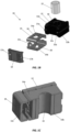
- the fuse module 10 may be coupled directly to a jump stud of a vehicle with no flexible electrical conductors extending therebetween and may provide overcurrent protection for a vehicle's battery.
- the fuse module 10 is provided in a compact, space-saving form factor that is amenable to convenient installation and removal.
- the fuse module 10 may include a mounting block 12 and a fuse plate 14 that extends around several surfaces of the mounting block 12.
- the fuse plate 14 may include an upper portion 14a disposed on a top surface 12a of the mounting block 12, a lower portion 14b disposed on a bottom surface 12b of the mounting block 12, and a fusible element 14c disposed adjacent a sidewall 12c of the mounting block 12 and connecting the upper portion 14a to the lower portion 14b.
- the mounting block 12 may include a through-hole 16 extending vertically therethrough.
- the upper and lower portions 14a, 14b of the fuse plate 14 may each have through-holes 18, 20 that are aligned with (e.g., concentric with) the through-hole 16 of the mounting block 12.
- the mounting block 12 may be formed of an electrically insulative, preferably lightweight material (e.g., any suitable plastic, polymer, composite, etc.).
- the fuse plate 14 may be formed of any suitable electrically conductive material conventionally used in fuse applications (e.g., copper, tin, etc.).
- the fusible element 14c of the fuse plate 14 may be mechanically weakened relative to other portions of the fuse plate 14 so that the fusible element 14c will melt and separate upon the occurrence of an overcurrent condition in the fuse module 10.
- the fusible element 14c may be narrower or thinner than other portions of the fuse plate 14.
- the present disclosure is not limited in this regard.
- the fusible element 14c may be perforated, notched, slotted, or otherwise structurally weakened to facilitate separation of the fusible element 14c if an amount of current flowing through the fuse plate 14 exceeds a predefined threshold ("current rating").
- the fuse module 10 may further include an electrically insulative cover 19 that fits over the fusible element 14c and that is affixed to the sidewall 12c of the mounting block 12.
- the cover 19 may be provided for shielding the fusible element 14c from environmental contaminants (e.g., ambient particulate) and containing electrical arcing that may occur upon separation of the fusible element 14c.
- the cover 19 may include mounting holes 17a, 17b that are configured to matingly engage corresponding mounting posts 21a, 21b extending from the sidewall 12c (e.g., via friction fit, snap fit, etc.).
- the present disclosure is not limited in this regard.
- the cover 19 may be affixed to the mounting block 12 using any other suitable means, including, but not limited to, mechanical fasteners, adhesives, etc.
- the fuse module 10 may further include a torque limiting cuff 22 disposed within the through-hole 16 of the mounting block 12 in a substantially coaxial relationship therewith.
- the torque limiting cuff 22 may be a tubular member formed of a rigid, electrically insulative material (e.g., ceramic) that extends between the upper portion 14a and the lower portion 14b of the fuse plate 14.
- the torque limiting cuff 22 may provide a hard stop to prevent the upper portion 14a and the lower portion 14b from being bent or deflected toward one another beyond a prescribed distance during installation of the fuse module 10 as further described below.
- the opposing ends of the torque limiting cuff 22 may be substantially coplanar with the top surface 12a and bottom surface 12b of the mounting block 12, respectively as shown in FIG. 1C .
- the present disclosure is not limited in this regard, and in various embodiments the torque limiting cuff 22 may be entirely omitted from the fuse module 10.
- the fuse module 10 is shown operatively installed as part of a jump stud assembly 30.
- the jump stud assembly 30 may be of a conventional variety familiar to those of skill in the art and may include a housing 32, electrically conductive first and second studs or posts 34a, 34b extending through a floor of the housing 32 and into a compartment 36 defined by the housing 32 (as best shown in FIGS. 2C and 2D ), and a removable cover 38 enclosing the compartment 36 (the removable cover 38 is omitted from FIG. 2C for clarity).
- the upper ends of the first and second studs 34a, 34b may be accessible via the open top of the compartment 36 for allowing jumper cables (not pictured) to be connected to the first and second studs 34a, 36b, for example.
- the housing 32 may include mounting flanges 40a, 40b with mounting holes formed therein for facilitating mounting of the jump stud assembly 30 to a vehicle with mechanical fasteners. The present disclosure is not limited in this regard.
- the fuse module 10 may be installed on a lower portion of the first stud 34a, below the floor of the housing 32, with the first stud 34a extending through the through-hole 16 of the mounting block 12.
- An electrically conductive first nut 42 may be secured to the first stud 34a (e.g., via threaded engagement) and may be sandwiched between the housing 32 and the upper portion 14a of the fuse plate 14.
- a ring terminal 44 of an insulated conductor 46 may be disposed in engagement with the lower portion 14b of the fuse plate 14 and may be sandwiched between the lower portion 14b and an electrically insulating ferrule 48.
- the ferrule 48 may have a planar portion 49 disposed in flat engagement with the lower portion 14b, and a tubular shank 50 that extends axially through the ring terminal 44 and the lower portion 14b of the fuse plate 14 and into the torque limiting cuff 22.
- the first nut 42, the fuse module 10, the ring terminal 44, and the ferrule 48 may be secured together in a stacked arrangement in the aforementioned order by a second nut 52 that threadedly engages the lower end of the first stud 34a.
- the torque limiting cuff 22 of the fuse module 10 may prevent over-tightening of the second nut 52 that could otherwise crush or crack the mounting block 12.
- a current path through the jump stud assembly 30 is established that is indicated by the arrows shown in FIG. 2E .
- current may flow into the first stud 34a (e.g., from a jumper cable clamped to the first stud 34a ), through the upper portion 14a of the fuse plate 14, through the fusible element 14c, though the lower portion 14b of the fuse plate 14, into the ring terminal 44 of the insulated conductor 46, and on to a load (e.g., a positive terminal 60 of a vehicle battery 62, see FIG. 2D ) that may be connected to an opposing end of the insulated conductor 46.
- a load e.g., a positive terminal 60 of a vehicle battery 62, see FIG. 2D
- current may flow in the opposite direction as well.
- the ferrule 48 which is formed of an electrically insulating material (e.g., plastic, rubber, ceramic, etc.) may provide an electrically insulating barrier that prevents current from flowing from the first stud 34a or the second nut 52 into the lower portion 14b of the fuse plate 14 or the ring terminal 44, thus forcing current to flow through the fusible element 14c instead of shorting through the first stud 34a.
- the fusible element 14c will melt and separate, thereby arresting current flowing through the jump stud assembly 30.
- the fuse module 10 thereby protects a connected load from overcurrent conditions that could otherwise cause damage to the load if allowed to persist.
- the insulated conductor 46 may extend to, and may be connected to, a positive terminal 60 of a vehicle battery 62 as schematically shown in FIG. 2D .
- a positive terminal 60 of a vehicle battery 62 as schematically shown in FIG. 2D .
- another insulated conductor may be connected to the second stud 34b and may extend to, and may be connected to, a negative terminal 64 of the vehicle battery 62.
- the jump stud assembly 30 can be contemplated in which another fuse module that is substantially identical to the fuse module 10 may be installed on the second stud 34b. The present disclosure is not limited in this regard.
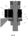
- FIG. 3 a detailed cross-sectional view illustrating the jump stud assembly 30 is shown.
- the assembly shown in FIG. 3 is generally similar to the jump stud assembly 30 described above and shown in FIGS. 2A-2E but may include an insulated bolt 70 for fastening the ring terminal 44 and the fuse module 10 to the first stud 34a.
- the first stud 34a may have a threaded aperture 72 formed in a lower end thereof.
- the insulated bolt 70 may extend through the ring terminal 44 and the fuse module 10 and may threadedly engage the threaded aperture 72, thus holding the ring terminal 44 in secure engagement with the lower portion 14b of the fuse plate 14 and holding the upper portion 14a of the fuse plate 14 in secure engagement with the first stud 34a.
- the insulated bolt 70 may include a head portion 74 and a shank portion 76 formed of metal (e.g., steel, titanium, etc.).
- a sleeve 78 formed of an electrically insulating material e.g., plastic, ceramic, etc.
- a washer 80 formed of an electrically insulating material e.g., plastic, ceramic, etc.
- the sleeve 78 and the washer 80 may be separate components or, alternatively, may be constituent parts of a single, unitary member (i.e., formed as a single piece of material).
- the sleeve 78 and the washer 80 may provide an electrically insulating barrier between the ring terminal 44 and the metal portions of the insulated bolt 70 and between the lower portion 14b of the fuse plate 14 and the metal portions of the insulated bolt 70. This may prevent electrical shorting between the ring terminal 44furreule and the first stud 34a and establishes a current path through the fusible element 14c that is substantially similar to that shown in FIG. 2E .
- the fuse module 10 may be connected directly to a jump stud of a vehicle with no flexible electrical conductors extending therebetween and may provide overcurrent protection for a vehicle's battery. Moreover, the fuse module 10 may provide such protection in a robust, compact form factor. Moreover, the fuse module 10 may be associated with relatively low manufacturing costs may therefore be implemented relatively inexpensively.
Landscapes
- Engineering & Computer Science (AREA)
- Life Sciences & Earth Sciences (AREA)
- Sustainable Development (AREA)
- Sustainable Energy (AREA)
- Power Engineering (AREA)
- Transportation (AREA)
- Mechanical Engineering (AREA)
- Chemical & Material Sciences (AREA)
- Chemical Kinetics & Catalysis (AREA)
- Electrochemistry (AREA)
- General Chemical & Material Sciences (AREA)
- Fuses (AREA)
Applications Claiming Priority (1)
| Application Number | Priority Date | Filing Date | Title |
|---|---|---|---|
| US18/533,284 US12387898B2 (en) | 2023-12-08 | 2023-12-08 | Jump stud fuse module |
Publications (1)
| Publication Number | Publication Date |
|---|---|
| EP4567855A1 true EP4567855A1 (de) | 2025-06-11 |
Family
ID=93842005
Family Applications (1)
| Application Number | Title | Priority Date | Filing Date |
|---|---|---|---|
| EP24218051.1A Pending EP4567855A1 (de) | 2023-12-08 | 2024-12-06 | Sicherungsmodul für sprungbolzen |
Country Status (2)
| Country | Link |
|---|---|
| US (1) | US12387898B2 (de) |
| EP (1) | EP4567855A1 (de) |
Citations (3)
| Publication number | Priority date | Publication date | Assignee | Title |
|---|---|---|---|---|
| US8669840B2 (en) * | 2010-05-18 | 2014-03-11 | Littelfuse, Inc. | Fuse assembly |
| US20160071678A1 (en) * | 2014-09-05 | 2016-03-10 | Littelfuse, Inc. | Mechanical disconnect switch with integrated fuse protection |
| US11636994B2 (en) * | 2021-03-24 | 2023-04-25 | Littlefuse, Inc. | Attaching an isolated single stud fuse to an electrical device |
Family Cites Families (5)
| Publication number | Priority date | Publication date | Assignee | Title |
|---|---|---|---|---|
| US6902434B2 (en) * | 2002-07-23 | 2005-06-07 | Cooper Technologies Company | Battery fuse bus bar assembly |
| US7192319B1 (en) * | 2005-11-28 | 2007-03-20 | Cooper Technologies Company | Insulated cable termination assembly and method of fabrication |
| DE102007033263A1 (de) * | 2007-07-17 | 2009-01-29 | Lear Corp., Southfield | Elektrischer Verbinder für einen Verdrahtungskabelbaum eines Fahrzeugs |
| US9728363B2 (en) * | 2015-11-25 | 2017-08-08 | Sumitomo Wiring Systems, Ltd. | Pre-fuse assembly with horizontal jump post |
| US10148044B2 (en) * | 2016-12-05 | 2018-12-04 | Littelfuse, Inc. | Battery terminal fuse module |
-
2023
- 2023-12-08 US US18/533,284 patent/US12387898B2/en active Active
-
2024
- 2024-12-06 EP EP24218051.1A patent/EP4567855A1/de active Pending
Patent Citations (3)
| Publication number | Priority date | Publication date | Assignee | Title |
|---|---|---|---|---|
| US8669840B2 (en) * | 2010-05-18 | 2014-03-11 | Littelfuse, Inc. | Fuse assembly |
| US20160071678A1 (en) * | 2014-09-05 | 2016-03-10 | Littelfuse, Inc. | Mechanical disconnect switch with integrated fuse protection |
| US11636994B2 (en) * | 2021-03-24 | 2023-04-25 | Littlefuse, Inc. | Attaching an isolated single stud fuse to an electrical device |
Also Published As
| Publication number | Publication date |
|---|---|
| US12387898B2 (en) | 2025-08-12 |
| US20250191867A1 (en) | 2025-06-12 |
Similar Documents
| Publication | Publication Date | Title |
|---|---|---|
| US5886611A (en) | Fuse assembly | |
| US7957156B2 (en) | Busbar circuit board assembly | |
| CN100521423C (zh) | 高压连接器盒 | |
| US8709628B2 (en) | Battery pack with connecting device | |
| KR20180099439A (ko) | 프레임 조립체 | |
| US11282667B2 (en) | Low profile integrated fuse module | |
| US6614203B2 (en) | Electrical connection box | |
| EP3552221B1 (de) | Sicherungsmodul für batterieklemme | |
| US12272893B2 (en) | Electrical connection structure | |
| JP2003009347A (ja) | 電気接続箱 | |
| US10770700B2 (en) | Battery pack | |
| US20030108789A1 (en) | Structure of connecting battery terminals to bus bars | |
| EP2801996A1 (de) | Überstromschutzvorrichtung | |
| US11189450B2 (en) | Low profile integrated fuse module | |
| EP4567855A1 (de) | Sicherungsmodul für sprungbolzen | |
| EP4064319B1 (de) | Befestigen einer isolierten einzelnen stiftsicherung an einer elektrischen vorrichtung | |
| EP4104197B1 (de) | Integriertes sicherungsmodul mit flachem profil | |
| JP6238873B2 (ja) | 電気接続箱 | |
| JP6424065B2 (ja) | スイッチボックス | |
| JP7845964B2 (ja) | 電気接続箱ユニット、端子付き電線の締結構造、及び、端子付き電線 | |
| US11081814B2 (en) | Wiring module | |
| US11823857B2 (en) | Fuse module with clamped fuse installation | |
| US11996716B1 (en) | Jumper cables with a grounding magnet assembly | |
| JP2020022235A (ja) | 電力変換装置及びバスバ | |
| JPH0970120A (ja) | 電気接続箱 |
Legal Events
| Date | Code | Title | Description |
|---|---|---|---|
| PUAI | Public reference made under article 153(3) epc to a published international application that has entered the european phase |
Free format text: ORIGINAL CODE: 0009012 |
|
| STAA | Information on the status of an ep patent application or granted ep patent |
Free format text: STATUS: THE APPLICATION HAS BEEN PUBLISHED |
|
| AK | Designated contracting states |
Kind code of ref document: A1 Designated state(s): AL AT BE BG CH CY CZ DE DK EE ES FI FR GB GR HR HU IE IS IT LI LT LU LV MC ME MK MT NL NO PL PT RO RS SE SI SK SM TR |
|
| STAA | Information on the status of an ep patent application or granted ep patent |
Free format text: STATUS: REQUEST FOR EXAMINATION WAS MADE |
|
| 17P | Request for examination filed |
Effective date: 20251203 |
|
| STAA | Information on the status of an ep patent application or granted ep patent |
Free format text: STATUS: EXAMINATION IS IN PROGRESS |
|
| 17Q | First examination report despatched |
Effective date: 20260112 |