EP4567860A2 - Guide d'ions rf - Google Patents
Guide d'ions rf Download PDFInfo
- Publication number
- EP4567860A2 EP4567860A2 EP25164338.3A EP25164338A EP4567860A2 EP 4567860 A2 EP4567860 A2 EP 4567860A2 EP 25164338 A EP25164338 A EP 25164338A EP 4567860 A2 EP4567860 A2 EP 4567860A2
- Authority
- EP
- European Patent Office
- Prior art keywords
- ion guide
- electrodes
- various aspects
- ion
- various embodiments
- Prior art date
- Legal status (The legal status is an assumption and is not a legal conclusion. Google has not performed a legal analysis and makes no representation as to the accuracy of the status listed.)
- Pending
Links
Images


Classifications
-
- H—ELECTRICITY
- H01—ELECTRIC ELEMENTS
- H01J—ELECTRIC DISCHARGE TUBES OR DISCHARGE LAMPS
- H01J49/00—Particle spectrometers or separator tubes
- H01J49/02—Details
- H01J49/06—Electron- or ion-optical arrangements
- H01J49/062—Ion guides
- H01J49/063—Multipole ion guides, e.g. quadrupoles, hexapoles
-
- H—ELECTRICITY
- H01—ELECTRIC ELEMENTS
- H01J—ELECTRIC DISCHARGE TUBES OR DISCHARGE LAMPS
- H01J49/00—Particle spectrometers or separator tubes
- H01J49/0027—Methods for using particle spectrometers
- H01J49/0031—Step by step routines describing the use of the apparatus
-
- H—ELECTRICITY
- H01—ELECTRIC ELEMENTS
- H01J—ELECTRIC DISCHARGE TUBES OR DISCHARGE LAMPS
- H01J49/00—Particle spectrometers or separator tubes
- H01J49/02—Details
- H01J49/06—Electron- or ion-optical arrangements
- H01J49/062—Ion guides
- H01J49/065—Ion guides having stacked electrodes, e.g. ring stack, plate stack
- H01J49/066—Ion funnels
-
- H—ELECTRICITY
- H01—ELECTRIC ELEMENTS
- H01J—ELECTRIC DISCHARGE TUBES OR DISCHARGE LAMPS
- H01J49/00—Particle spectrometers or separator tubes
- H01J49/02—Details
- H01J49/24—Vacuum systems, e.g. maintaining desired pressures
-
- H—ELECTRICITY
- H01—ELECTRIC ELEMENTS
- H01J—ELECTRIC DISCHARGE TUBES OR DISCHARGE LAMPS
- H01J49/00—Particle spectrometers or separator tubes
- H01J49/26—Mass spectrometers or separator tubes
- H01J49/34—Dynamic spectrometers
- H01J49/42—Stability-of-path spectrometers, e.g. monopole, quadrupole, multipole, farvitrons
- H01J49/4205—Device types
- H01J49/4255—Device types with particular constructional features
-
- H—ELECTRICITY
- H01—ELECTRIC ELEMENTS
- H01J—ELECTRIC DISCHARGE TUBES OR DISCHARGE LAMPS
- H01J49/00—Particle spectrometers or separator tubes
- H01J49/26—Mass spectrometers or separator tubes
- H01J49/34—Dynamic spectrometers
- H01J49/42—Stability-of-path spectrometers, e.g. monopole, quadrupole, multipole, farvitrons
- H01J49/426—Methods for controlling ions
Definitions
- the applicant's teachings relate to a method and apparatus for transporting ions in a mass spectrometer, and more specifically to RF ion guides.
- sample molecules are converted into ions using an ion source, in an ionization step, and then detected by a mass analyzer, in mass separation and detection steps.
- ions pass through an inlet aperture prior to entering an ion guide in a first vacuum chamber.
- the ion guide transports and focuses ions from the ion source into a subsequent vacuum chamber, and a radio frequency signal can be applied to the ion guide to provide radial focusing of ions within the ion guide.
- ion losses can occur. Therefore, it is desirable to increase transport efficiency of the ions along the ion guide and prevent the loss of ions during transportation to attain high sensitivity.
- a mass spectrometer apparatus comprising an ion source for generating ions from a sample in a high-pressure region.
- a first vacuum chamber has an inlet aperture for passing the ions from the high-pressure region into the first vacuum chamber and an exit aperture for passing ions from the first vacuum chamber.
- the apparatus also comprises at least one ion guide.
- the at least one ion guide can be positioned in the chamber between the inlet aperture and an exit aperture so that when an RF voltage, provided by an RF power supply, is applied to the at least one ion guide, the ions can be radially confined within the internal volume of the at least one ion guide and focused and directed to the exit aperture.
- the at least one ion guide has an entrance end and an exit end.
- the at least one ion guide can comprise a predetermined cross section and length defining an internal volume.
- the predetermined cross section of the at least one ion guide can form an inscribed circle.
- the entrance end comprises an opening with an inscribed circle that is larger than the inscribed circle that comprises the exit end.
- the inscribed circle at the entrance end has a diameter of between about 8 mm and about 20 mm.
- the size of the inlet and exit apertures can dictate the diameter of the entrance and exit ends of the ion guide.
- the entrance end of the ion guide has a diameter of between about 7 mm and about 12 mm.
- the inscribed circle at the exit end has a diameter of between about 1.5 mm and about 10 mm.
- the exit end of the ion guide has a diameter between about 1.5 mm and about 2.5 mm.
- the at least one ion guide comprises a plurality of electrodes arranged around a central axis defining an ion channel.
- each of the plurality of electrodes can be tapered, and a planar surface of each of the plurality of tapered electrodes can face the interior of the at least one ion guide, the surface gradually being narrowed and tilting inward to provide a smaller inscribed radius at the exit.
- the surface of each of the plurality of tapered electrodes can be any suitable shape.
- the surface can be curved.
- the surface can be convex or concave.
- a power supply can provide an RF voltage to the at least one ion guide.
- the spacing between adjacent electrodes is essentially constant over the length of the ion guide. In various aspects, the spacing between adjacent electrodes is between about 0.4 mm to about 1.5 mm. In various embodiments, each of the plurality of electrodes gradually becomes thicker towards the narrower exit end of the ion guide, the thickness being in the direction approximately perpendicular to the central axis. In various embodiments, each of the plurality of electrodes can be approximately four times thicker at the exit end than at the entrance end. In various aspects, the length of the electrodes comprises between about 5 cm to about 50 cm.
- the diameter of the inlet aperture can be between about 0.15 mm to about 5 mm. In various aspects, the diameter of the exit aperture can be about 0.5 mm to about 20 mm.
- the at least one ion guide can be attached to a printed circuit board. In various aspects, the first vacuum chamber can have a pressure between about 1 torr to about 100 torr. In various embodiments, the first vacuum chamber can have a pressure between about 6 torr and about 12 torr. In various aspects, the at least one ion guide can comprise a multipole. In various embodiments, the multipole can comprise any suitable number of electrodes. In various aspects, the multipole can comprise any even number of electrodes.
- the multipole can be selected from an ion guide having four electrodes, six electrodes, eight electrodes, ten electrodes, twelve electrodes, fourteen electrodes, and sixteen electrodes.
- twelve electrodes are provided that are separated by a gap of approximately 0.4 mm and have a thickness in the direction approximately perpendicular to the central axis that increases from approximately 1.5 mm at the entrance end to approximately 6 mm at the exit end.
- the method comprises an ion source for generating ions from a sample in a high-pressure region.
- a first vacuum chamber having an inlet aperture for passing the ions from the high-pressure region into the first vacuum chamber and an exit aperture for passing ions from the first vacuum chamber.
- the method also comprises at least one ion guide.
- the at least one ion guide can be positioned in the chamber between the inlet aperture and an exit aperture so that when an RF voltage, provided by an RF power supply, is applied to the at least one ion guide, the ions can be radially confined within the internal volume of the at least one ion guide and focused and directed to the exit aperture.
- the method comprises a second vacuum chamber following the first vacuum chamber, where the pressure in the second vacuum chamber is lower than the pressure in the first vacuum chamber.
- a second ion guide in the second vacuum chamber can be provided to further focus the ions through the second vacuum chamber.
- the at least one ion guide has an entrance end and an exit end.
- the entrance end comprises an opening with an inscribed circle that is larger than the inscribed circle that comprises the exit end.
- the inscribed circle at the entrance end has a diameter of between about 8 mm and about 20 mm.
- the inscribed circle at the exit end has a diameter of between about 1.5 mm and about 10 mm.
- the size of the inlet and exit apertures can dictate the diameter of the entrance and exit ends of the ion guide.
- the entrance end of the ion guide has a diameter of between about 7 mm and about 12 mm.
- the exit end of the ion guide has a diameter between about 1.5 mm and about 2.5 mm.
- the at least one ion guide comprises a plurality of electrodes arranged around a central axis defining an ion channel.
- each of the plurality of electrodes being tapered, and a planar surface of each of the plurality of tapered electrodes facing the interior of the at least one ion guide, the surface gradually being narrowed and tilted inward to provide a smaller inscribed radius at the exit.
- the surface of each of the plurality of tapered electrodes can be any suitable shape.
- the surface can be curved.
- the surface can be convex or concave.
- a power supply can provide an RF voltage to the at least one ion guide.
- the spacing between adjacent electrodes is essentially constant over the length of the ion guide. In various aspects, the spacing between adjacent electrodes is between about 0.4 mm to about 1.5 mm. In various embodiments, each of the plurality of electrodes gradually becomes thicker towards the narrower exit end of the ion guide, the thickness being in the direction approximately perpendicular to the central axis. In various embodiments, each of the plurality of electrodes can be approximately four times thicker at the exit end than at the entrance end. In various aspects, the length of the electrodes comprises between about 5 cm to about 50 cm.
- each of the plurality of electrodes can be folded, or bent, along the length of the ion guide to form a gradually narrowing planar surface that faces the interior of the at least one ion guide.
- the planar surface can become narrower towards the end of each of the electrodes.
- a second planar surface is approximately orthogonal to the axis of the ion guide.
- a power supply can provide an RF voltage to the at least one ion guide.
- the plurality of electrodes can be folded at about 90 degrees.
- each of the plurality of electrodes can be tapered.
- the length of the electrodes can be between about 5 cm and about 50 cm.
- the spacing between adjacent electrodes can be constant and can be between about 0.1 mm to about 1.5 mm.
- the diameter of the inlet aperture can be between about 0.15 mm to about 5 mm.
- the diameter of the exit aperture can be about 0.5 mm to about 20 mm.
- the size of the inlet and exit apertures can dictate the diameter of the entrance and exit ends of the ion guide.
- the entrance end of the ion guide has a diameter of between about 7 mm and about 12 mm. In various embodiments, the exit end of the ion guide has a diameter between about 1.5 mm and about 2.5 mm.
- the at least one ion guide can be attached to a printed circuit board.
- the first vacuum chamber can have a pressure between about 1 torr to about 100 torr. In various embodiments, the first vacuum chamber can have a pressure between about 6 torr and about 12 torr.
- the electrodes can be comprised of sheet or shim metal. In various embodiments, the electrodes can be machined. In various aspects, the at least one ion guide can comprise a multipole.
- the multipole can comprise any suitable number of electrodes. In various aspects, the multipole can have any even number of electrodes. In various embodiments, the multipole can be selected from an ion guide having four electrodes, six electrodes, eight electrodes, ten electrodes, twelve electrodes, fourteen electrodes, and sixteen electrodes.
- a first vacuum chamber can be provided having an inlet aperture for passing the ions from the high-pressure region into the first vacuum chamber and an exit aperture for passing ions from the first vacuum chamber.
- at least one ion guide can be provided between the inlet aperture and the exit aperture.
- the at least one ion guide has an entrance end and an exit end.
- the at least one ion guide comprises a plurality of planar electrodes arranged around a central axis defining an ion channel.
- each of the plurality of electrodes can be folded, or bent, along the length of the ion guide to form a gradually narrowing planar surface that faces the interior of the at least one ion guide.
- the planar surface can become narrower towards the end of each of the electrodes.
- a second planar surface can be approximately orthogonal to the axis of the ion guide.
- a power supply can be provided for providing an RF voltage to the at least one ion guide.
- the plurality of electrodes can be folded at about 90 degrees.
- each of the plurality of electrodes can be tapered.
- the length of the electrodes can be between about 5 cm and about 50 cm.
- the spacing between adjacent electrodes can be constant and can be between about 0.1 mm to about 1.5 mm.
- the diameter of the inlet aperture can be between about 0.15 mm to about 5 mm.
- the diameter of the exit aperture can be about 0.5 mm to about 20 mm.
- the size of the inlet and exit apertures can dictate the diameter of the entrance and exit ends of the ion guide.
- the entrance end of the ion guide has a diameter of between about 7 mm and about 12 mm. In various embodiments, the exit end of the ion guide has a diameter between about 1.5 mm and about 2.5 mm.
- the at least one ion guide can be attached to a printed circuit board.
- the first vacuum chamber can have a pressure between about 1 torr to about 100 torr. In various embodiments, the first vacuum chamber can have a pressure between about 6 torr and about 12 torr.
- the electrodes can be comprised of metal. In various embodiments, the electrodes can be formed from sheet or shim metal. In various aspects, the at least one ion guide can comprise a multipole.
- the multipole can comprise any suitable number of electrodes. In various aspects, the multipole can have any even number of electrodes. In various embodiments, the multipole can be selected from an ion guide having four electrodes, six electrodes, eight electrodes, ten electrodes, twelve electrodes, fourteen electrodes, and sixteen electrodes.
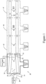
- FIG. 1 shows schematically a mass spectrometer, generally indicated by reference number 20 according to various embodiments of the applicant's teachings.
- the mass spectrometer 20 comprises an ion source 22 for generating ions 24 from a sample of interest, not shown.
- the ion source 22 can be positioned in a high-pressure region containing a background gas, while the ions 24 travel towards a first vacuum chamber 26, in the direction indicated by the arrow 38.
- the ions enter the chamber 26 through an inlet aperture 28, where the ions are entrained by a supersonic flow of gas, typically referred to as a supersonic free jet expansion as described, for example, in applicant's U.S. patents 7,256,395 and 7,259,371 herein incorporated by reference.
- a supersonic flow of gas typically referred to as a supersonic free jet expansion as described, for example, in applicant's U.S. patents 7,256,395 and 7,259,371 herein incorporated by reference.
- the ions 24 can travel towards a first vacuum chamber 26, in the direction indicated by the arrow 38.
- a vacuum pump 42 can provide suitable vacuum to first vacuum chamber 26.
- the first vacuum chamber can comprise a pressure between about 1 torr to about 100 torr.
- the first vacuum chamber can have a pressure between about 6 torr and about 12 torr.
- the pressure in the first vacuum chamber 26 can be maintained by pump 42, and power supply 40 can be connected to the at least one ion guide 36 to provide RF voltage in a known manner for radially confining, focusing, and passing ions 24 from the first vacuum chamber 26.
- the first vacuum chamber 26 can comprise an inlet aperture 28 for passing the ions into the first vacuum chamber 26 and an exit aperture 32 located downstream from the inlet aperture 28.
- the exit aperture 32 can separate the first vacuum chamber 26 from the next or second vacuum chamber 45 which can house a further ion guide 56, as exemplified in Figures 1 , 4 and 7 .
- the pressure of the second vacuum chamber can be between about 1 torr and about 3 torr.
- a vacuum pump 42b can provide suitable vacuum to second vacuum chamber 45.
- subsequent vacuum chambers, 46 and 47 can be provided with respective vacuum pumps, 42c and 42d.
- Vacuum chambers 46 and 47 can house an ion guide 60 or mass analyzer 64. Vacuum chamber 47 can further comprise stubby rods 62.
- one or more power supplies can supply voltages to ion guides 36 and 56.
- declustering voltages can be provided between apertures and RF ion guides in order to decluster ions.
- Declustering voltages can comprise DC voltage differences between ion optical elements such as metal plates containing apertures and RF ions guides, or between two RF ion guides, the DC voltage difference acting to increase the velocity of ions in the background gas, exciting the ions by means of collisions to remove any residual neutral clusters that remain on the ions, or even to fragment ions if so desired.
- the DC voltage differences can be provided to various ion optical elements by DC power supplies (not shown) in a known manner.
- declustering voltages can be controlled in order to control the amount of declustering or fragmentation, as is known in the art.
- declustering or fragmentation voltages can be provided, for example, between the plate containing the inlet aperture 28 and the first RF ion guide 36, between ion guide 36 and the plate containing exit aperture 32, or between exit aperture 32 and RF ion guide 56, or between the vacuum chambers 45 and 46.
- more than one declustering voltage in more than one location can be applied.
- RF ion guides 36 or 56 can comprise two or more segments.
- declustering voltages can be provided between two or more segments of RF ion guides located in any of said vacuum chambers 26, 45, 46 or 47. In various embodiments, declustering voltages can be provided between any ion optical element such as a plate aperture or ion focusing lens or RF ion guide, and any adjacent ion optical elements through which the ions are directed.
- any ion optical element such as a plate aperture or ion focusing lens or RF ion guide, and any adjacent ion optical elements through which the ions are directed.
- the at least one ion guide 36 of Figure 1 can comprise a plurality of electrodes arranged around a central axis defining an ion channel.
- the plurality of electrodes can be tapered, a planar surface of each of the plurality of tapered electrodes facing the interior of the at least one ion guide, and the surface gradually being narrowed and tilting inward to provide a smaller inscribed radius at the exit end.
- the surface of each of the plurality of tapered electrodes can be any suitable shape. In various aspects, the surface can be curved.
- the surface can be convex or concave.
- a power supply can provide an RF voltage to the at least one ion guide.
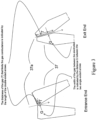
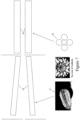
- Figure 2 shows a top view or view from the entrance of the multipole as well as a single electrode 37.
- each of the plurality of electrodes gradually becomes thicker towards the narrower exit end of the ion guide, the thickness being in the direction approximately perpendicular to the central axis of the ion guide. In various aspects, each of the plurality of electrodes is approximately four times thicker at the exit end than at the entrance end.
- the spacing between adjacent electrodes can be essentially constant over the length of the ion guide. In various aspects, the spacing between adjacent electrodes can be between about 0.4 mm to about 1.5 mm.
- the gas flow through inlet aperture 28 comprises a free jet expansion, in which the gas and ions are directed at high velocities through a barrel-shaped region into the interior of the RF ion guide as described, for example, in applicant's U.S. patents 7,256,395 and 7,259,371 herein incorporated by reference.
- the entrance diameter of RF ion guide 36 can be selected to be at least 80% of the diameter of the barrel shock of the free jet. This ensures that a large proportion of the ions that are entrained in the free jet is captured by the RF ion guide, and can be focused by the RF fields in the ion guide.
- the width of the gap G (dimension indicated by the distance between the two single-ended solid arrows) between adjacent electrodes, combined with the thickness of the electrodes T (dimension indicated by the double-ended solid arrows) in a direction perpendicular to the axis of the ion guide, comprises a channel through which the gas 37a, indicated by the dotted arrows, must flow to escape from the interior of the ion guide.
- the resistance to radial gas flow can be greater at the exit end of the ion guide because the electrodes 37 are thicker at the exit end than at the entrance end, thereby reducing the gas conductance or increasing the resistance to radial gas flow.
- the thicker channel comprises a greater resistance to gas flow than does a thinner channel, thereby reducing the radial gas flow outward at the exit end than at the entrance end. This reduces the tendency of the gas to drag the ions outward through the gaps of the ion guide, thereby improving the ability of the RF ion guide to contain the ions within the ion guide, and to focus the ions through the exit aperture 32.
- the ion guide can comprise twelve electrodes, each electrode separated from adjacent electrodes by a gap of approximately 0.4 mm.
- the twelve electrodes can have a thickness T in the direction approximately perpendicular to the central axis that increases from approximately 1.5 mm at the entrance end to approximately 6 mm at the exit end. In various embodiments, the thickness T is approximately 4 times greater at the exit than at the entrance.
- the length of the electrodes is between about 5 cm to about 50 cm.
- the diameter of the inlet aperture 28 is about 0.15 mm to about 5 mm.
- the diameter of the exit aperture 32 is about 0.5 mm to about 20 mm.
- the size of the inlet and exit apertures can dictate the diameter of the entrance and exit ends of the ion guide.
- the diameter of the entrance end of the ion guide can be selected to be at least 80% of the diameter of the diameter of the free jet.
- the entrance end of the ion guide can have a diameter of between about 7 mm and about 12 mm.
- the exit end of the ion guide has a diameter between about 1.5 mm and about 2.5 mm.
- the pressure of the first vacuum chamber can be between about 1 torr to about 100 torr. In various embodiments, the first vacuum chamber can have a pressure between about 6 torr and about 12 torr.
- the at least one ion guide can comprise a series of multipole ion guides.
- the series of multipole ion guides can comprise any suitable configuration of rods.
- the at least one guide 36 can comprise the plurality of electrodes of Figure 2
- the at least second ion guide 56 can comprise flat, T-shaped rods 58.
- the T-shaped rods can have flat surfaces that can face the interior of the ion guide.
- the at least second ion guide can have an entrance end diameter that is larger than the exit end diameter.
- the stems of the T-shaped electrodes can be tilted so that the exit end diameter is smaller than the entrance end diameter.
- the at least second ion guide can have an entrance end diameter that can be selected to capture the ion beam that is emitted from the first ion guide.
- the second ion guide can comprise electrodes that are round, flat, rectangular, oval, T-shaped, or any other suitable shape.
- the second ion guide can comprise a ring guide or ion funnel as is known in the art.
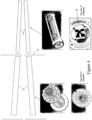
- Figure 4 shows a top view of the multipole of the first ion guide 36 and a top view of the multipole of the second ion guide 56.
- the second ion guide may converge toward the exit as shown in Figure 4 , or may be straight so that the entrance and exit ends are of the same diameter.
- the first ion guide and second ion guide can have RF frequencies of between about 1 MHz and about 10 MHz.
- the first ion guide can have an RF frequency of about 3 MHz
- the second ion guide can have an RF frequency of about 1.5 MHz.
- the ion guides can have voltages between about 20 volts and about 300 volts. As is known in the art, the RF voltages of the ion guides can be adjusted to provide optimum transmission of different m/z values of the ions.
- the RF voltages of the ion guides can be scanned as a function of the m/z value of the first mass filter or scanned in order to provide the desired or suitable transmission efficiency. In various embodiments, the RF voltage of the ion guides can be selected to reduce the transmission efficiency of ions of selected mass range in order to reduce the ion flux.
- the RF voltage of any of the ion guides in the mass spectrometer can be used to throttle the intensity of the ion beam by suitably increasing or decreasing the RF voltage or the RF frequency from the value that provides maximum transmission.
- the RF voltage of the second ion guide can be selected to be a fixed percentage or ratio of the RF voltage of the first ion guide. In various embodiments, the RF voltage of the second ion guide can be provided by dividing the RF voltage from the first ion guide through a capacitive divider as is known in the art.
- the at least one ion guide can comprise a first ion guide 36 followed by at least a second ion guide 56 wherein the at least second ion guide 56 comprises a smaller diameter than the first ion guide 36.
- the series of multipole ion guides can include any number of electrodes, including quadrupole, hexapole, octapole, higher number of poles, or any combination thereof.
- the second ion guide, 56 can be located in a separate vacuum chamber, separated from the first vacuum chamber by an aperture plate, 33, as shown in Figure 4 .
- the pressure in the second chamber can be at a lower pressure than the pressure in the first vacuum chamber.
- the pressure in the first vacuum chamber can be in the range of about 6 torr to about 12 torr.
- the pressure in the second vacuum chamber can be in the range of between about 1 torr to about 3 torr.
- the second ion guide can be located in the same vacuum chamber, at the same pressure, as the first ion guide.
- the at least first and second ion guides can be mounted on a single flange as a unit which can be removed for service or replacement. Each ion guide can be separately removable from the flange.
- the flange can accommodate the RF connections and the capacitive divider so that connection to the RF power supply can be provided by inserting the flange into position, the RF connections being made by a suitable series of electrical plugs and sockets on the mounting chamber.
- the at least one ion guide 36 of Figure 1 can comprise a plurality of planar electrodes 52 defining an ion channel, each of the plurality of planar electrodes being folded, or bent, along the length of the ion guide to form a gradually narrowing planar surface 39 that faces the interior of the at least one ion guide.
- the planar surface can become narrower towards the end of each of the electrodes.
- each of the plurality of electrodes can be tapered.
- a second planar surface, 41 is approximately orthogonal to the axis of the ion guide.
- a power supply can provide an RF voltage to the at least one ion guide.
- the plurality of electrodes can be folded at about 90 degrees.
- the length of the electrodes can be between about 5 cm to about 50 cm.
- the spacing between adjacent electrodes can be constant and can be between about 0.1 mm to about 1.5 mm.
- the diameter of the inlet aperture can be between about 0.15 mm to about 5 mm.
- the diameter of the exit aperture can be between about 0.5 mm to about 20 mm.
- the size of the inlet and exit apertures can dictate the diameter of the entrance and exit ends of the ion guide.
- the entrance end of the ion guide has a diameter of between about 7 mm and about 12 mm.
- the exit end of the ion guide has a diameter between about 1.5 mm and about 2.5 mm.
- the electrodes of the at least one ion guide can be individually attached or soldered to a printed circuit board at the entrance end and a printed circuit board at the exit end.
- the printed circuit boards can provide a mechanical mounting for the electrodes and can provide electrical connections to the electrodes. Electrical components such as capacitors or resistors which supply RF and DC voltages to the electrodes of the ion guide can be mounted or soldered on the printed circuit board.
- the printed circuit board can contain all circuit connections and tracks as is known in conventional printed circuit boards in order to reduce the need to use wires to connect individual components.
- the aperture plates containing the apertures such as aperture 32 in Figure 1 can be mounted on the printed circuit board.
- the printed circuit board can form part of the vacuum barrier between adjacent chambers.
- the pressure of the first vacuum chamber can be between about 1 torr to about 100 torr.
- the first vacuum chamber can have a pressure between about 6 torr and about 12 torr.
- the electrodes can be comprised of metal.
- the electrodes can be formed from sheet or shim metal.
- the at least one ion guide can comprise a multipole.
- the multipole can comprise any suitable number of electrodes.
- the multipole can comprise any even number of electrodes.
- the multipole can be selected from four electrodes, six electrodes, eight electrodes, ten electrodes, twelve electrodes, fourteen electrodes, and sixteen electrodes.
- a power supply can provide an RF voltage to the at least one ion guide.
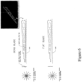
- Figure 6 shows a flat blade, which can comprise a thin, flat piece of metal that can be folded or bent along a line, as shown in Figure 5 , to form a planar surface.
- the at least one ion guide can comprise a series of multipole ion guides as shown in Figure 7 .
- the at least one guide 36 can comprise a plurality of electrodes of Figure 5
- the at least second ion guide 56 can comprise quadrupole rods 58 or any other type of rods.
- the at least one ion guide can comprise a first ion guide 36 followed by at least a second ion guide 56 wherein the at least second ion guide 56 comprises a smaller diameter than the first ion guide 36.
- the at least one ion guide and the subsequent series of ion guides can comprise planar electrodes or rods or a combination thereof.
- the series of multipole ion guides can include any number of electrodes, including quadrupole, hexapole, octapole, higher number of poles, or any combination thereof.
- a method for performing mass analysis comprising providing an ion source for generating ions from a sample in a high pressure region.
- a vacuum chamber is provided comprising an inlet aperture for passing the ions from the high-pressure region into the vacuum chamber and an exit aperture for passing ions from the vacuum chamber.
- at least one ion guide can be provided between the inlet and exit apertures, and the at least one ion guide can comprise an entrance end and an exit end.
- the at least one ion guide can have a plurality of electrodes arranged around a central axis defining an ion channel, each of the plurality of electrodes being tapered, a planar surface of each of the plurality of tapered electrodes can face the interior of the at least one ion guide, and the surface being gradually narrowed and tilting inward to provide a smaller inscribed radius at the exit end.
- the surface of each of the plurality of tapered electrodes can be any suitable shape.
- the surface can be curved.
- the surface can be convex or concave.
- a power supply can be provided for providing an RF voltage to the at least one ion guide.
- the resistance to gas flow can be greater at the exit end of the ion guide because the electrodes are thicker at the exit end than the entrance end, thereby reducing the gas conductance or increasing the resistance to the radial gas flow.
- the spacing between adjacent electrodes can be essentially constant over the length of the ion guide. In various aspects, the spacing between adjacent electrodes can be between about 0.4 mm to about 1.5 mm.
- each of the plurality of electrodes gradually becomes thicker towards the narrower exit end of the ion guide, the thickness being in the direction approximately perpendicular to the central axis. In various embodiments, each of the plurality of electrodes can be approximately four times thicker at the exit end than at the entrance end.
- the length of the electrodes can between about 5 cm to about 50 cm.
- the diameter of the inlet aperture is about 0.15 mm to about 5 mm.
- the diameter of the exit aperture is about 0.5 mm to about 20 mm.
- the size of the inlet and exit apertures can dictate the diameter of the entrance and exit ends of the ion guide.
- the entrance end of the ion guide has a diameter of between about 7 mm and about 12 mm.
- the exit end of the ion guide has a diameter between about 1.5 mm and about 2.5 mm.
- the at least one ion guide can be attached to a printed circuit board.
- the pressure of the first vacuum chamber can be between about 1 torr to about 100 torr. In various embodiments, the first vacuum chamber can have a pressure between about 6 torr and about 12 torr.
- the at least one ion guide can comprise a multipole.
- the multipole can comprise any suitable number of electrodes.
- the multipole can comprise any even number of electrodes.
- the multipole is selected from four electrodes, six electrodes, eight electrodes, ten electrodes, twelve electrodes, fourteen electrodes, and sixteen electrodes.
- twelve electrodes are provided that are separated by a gap of approximately 0.4 mm and have a thickness in the direction approximately perpendicular to the central axis that increases from approximately 1.5 mm at the entrance end to approximately 6 mm at the exit end.
- the at least one ion guide can comprise a series of multipole ion guides.
- the at least one guide 36 can comprise the plurality of electrodes of Figure 2
- the at least second ion guide 56 can comprise quadrupole rods.
- the at least one ion guide can comprise a first ion guide followed by at least a second ion guide wherein the at least second ion guide comprises a smaller diameter than the first ion guide.
- the at least one ion guide and the subsequent series of ion guides can comprise planar electrodes or rods or a combination thereof.
- the series of multipole ion guides can include any number of electrodes, including quadrupole, hexapole, octapole, higher number of poles, or any combination thereof.
- a method for performing mass analysis comprising generating ions from a sample in a high pressure region.
- the ions can pass into a vacuum chamber comprising an inlet aperture for passing the ions from the high-pressure region into the vacuum chamber.
- an exit aperture can be provided for passing ions from the vacuum chamber.
- the at least one ion guide between the inlet and exit apertures, the at least one ion guide can have an entrance end and an exit end, the at least one ion guide can have a plurality of planar electrodes defining an ion channel, each of the plurality of planar electrodes being folded, or bent, along the length of the ion guide to form a gradually narrowing planar surface that faces the interior of the at least one ion guide.
- the planar surface can become narrower towards the end of each of the electrodes.
- each of the plurality of electrodes can be tapered.
- a second planar surface is approximately orthogonal to the axis of the ion guide.
- an RF voltage can be applied to the at least one ion guide.
- the plurality of planar electrodes can be folded at about 90 degrees.
- the length of the electrodes comprises between about 5 cm to about 50 cm.
- the spacing between the plurality of electrodes can be constant and can be between about 0.1 mm to about 1.5 mm.
- the diameter of the inlet aperture can be between about 1.5 mm to about 5 mm.
- the diameter of the exit aperture can be between about 0.5 mm to about 20 mm.
- the size of the inlet and exit apertures can dictate the diameter of the entrance and exit ends of the ion guide.
- the entrance end of the ion guide has a diameter of between about 7 mm and about 12 mm.
- the exit end of the ion guide has a diameter between about 1.5 mm and about 2.5 mm.
- the at least one ion guide can be attached to a printed circuit board.
- the first vacuum chamber can have a pressure between about 1 torr to about 100 torr. In various embodiments, the first vacuum chamber can have a pressure between about 6 torr and about 12 torr.
- the electrodes can be comprised of metal.
- the at least one ion guide comprises a multipole.
- the multipole can comprise any even number of electrodes.
- the multipole is selected from four electrodes, six electrodes, eight electrodes, ten electrodes, twelve electrodes, fourteen electrodes, and sixteen electrodes.
- the at least one ion guide can comprise a series of multipole ion guides.
- the at least one guide 36 can comprise the plurality of electrodes of Figure 5
- the at least second ion guide 56 can comprise quadrupole rods.
- the at least second ion guide can be comprised of T-shaped electrodes.
- the at least one ion guide can comprise a first ion guide followed by at least a second ion guide wherein the at least second ion guide comprises a smaller diameter than the first ion guide.
- the at least second ion guide can comprise an entrance end diameter that is larger than the exit end diameter.
- the at least one ion guide and the subsequent series of ion guides can comprise planar electrodes or rods or a combination thereof.
- the series of multipole ion guides can comprise any number of electrodes, including quadrupole, hexapole, octapole, higher number of poles, or any combination thereof.
Landscapes
- Chemical & Material Sciences (AREA)
- Analytical Chemistry (AREA)
- Electron Tubes For Measurement (AREA)
- Other Investigation Or Analysis Of Materials By Electrical Means (AREA)
Priority Applications (1)
| Application Number | Priority Date | Filing Date | Title |
|---|---|---|---|
| EP25164338.3A EP4567860A3 (fr) | 2014-11-28 | 2014-11-28 | Guide d'ions rf |
Applications Claiming Priority (3)
| Application Number | Priority Date | Filing Date | Title |
|---|---|---|---|
| EP14907051.8A EP3224856B1 (fr) | 2014-11-28 | 2014-11-28 | Guide d'ions rf |
| EP25164338.3A EP4567860A3 (fr) | 2014-11-28 | 2014-11-28 | Guide d'ions rf |
| PCT/IB2014/002629 WO2016083857A1 (fr) | 2014-11-28 | 2014-11-28 | Guide d'ions rf |
Related Parent Applications (2)
| Application Number | Title | Priority Date | Filing Date |
|---|---|---|---|
| EP14907051.8A Division-Into EP3224856B1 (fr) | 2014-11-28 | 2014-11-28 | Guide d'ions rf |
| EP14907051.8A Division EP3224856B1 (fr) | 2014-11-28 | 2014-11-28 | Guide d'ions rf |
Publications (2)
| Publication Number | Publication Date |
|---|---|
| EP4567860A2 true EP4567860A2 (fr) | 2025-06-11 |
| EP4567860A3 EP4567860A3 (fr) | 2025-08-06 |
Family
ID=56073680
Family Applications (2)
| Application Number | Title | Priority Date | Filing Date |
|---|---|---|---|
| EP14907051.8A Active EP3224856B1 (fr) | 2014-11-28 | 2014-11-28 | Guide d'ions rf |
| EP25164338.3A Pending EP4567860A3 (fr) | 2014-11-28 | 2014-11-28 | Guide d'ions rf |
Family Applications Before (1)
| Application Number | Title | Priority Date | Filing Date |
|---|---|---|---|
| EP14907051.8A Active EP3224856B1 (fr) | 2014-11-28 | 2014-11-28 | Guide d'ions rf |
Country Status (6)
| Country | Link |
|---|---|
| US (1) | US10475633B2 (fr) |
| EP (2) | EP3224856B1 (fr) |
| JP (1) | JP6483260B2 (fr) |
| CN (1) | CN107004566B (fr) |
| CA (1) | CA2968312A1 (fr) |
| WO (1) | WO2016083857A1 (fr) |
Families Citing this family (16)
| Publication number | Priority date | Publication date | Assignee | Title |
|---|---|---|---|---|
| CN106373854B (zh) * | 2015-07-23 | 2018-12-21 | 株式会社岛津制作所 | 一种离子导引装置 |
| US11728153B2 (en) * | 2018-12-14 | 2023-08-15 | Thermo Finnigan Llc | Collision cell with enhanced ion beam focusing and transmission |
| CN109994365A (zh) * | 2019-04-10 | 2019-07-09 | 江苏天瑞仪器股份有限公司 | 一种长轴多级杆离子聚焦传输部件 |
| CN110010443B (zh) * | 2019-04-10 | 2024-09-03 | 江苏天瑞仪器股份有限公司 | 一种折线递进式多级杆离子聚焦传输设备及装置 |
| CN110010442A (zh) * | 2019-04-10 | 2019-07-12 | 江苏天瑞仪器股份有限公司 | 一种喇叭口型带电粒子聚焦传输装置 |
| CN109994366A (zh) * | 2019-04-10 | 2019-07-09 | 江苏天瑞仪器股份有限公司 | 一种折弯型多级杆离子聚焦传输部件 |
| CN114641845B (zh) * | 2019-11-28 | 2025-10-14 | 株式会社岛津制作所 | 质量分析装置 |
| EP3916231A1 (fr) * | 2020-05-29 | 2021-12-01 | Agilent Technologies, Inc. | Système de pompage à vide doté d'une pluralité de pompes sous vide à déplacement positif et son procédé de fonctionnement |
| CN113871286A (zh) * | 2020-06-30 | 2021-12-31 | 安捷伦科技有限公司 | 具有不同多极的离子导向器 |
| CN113871284B (zh) * | 2020-06-30 | 2025-04-25 | 株式会社岛津制作所 | 质谱仪 |
| US11515137B2 (en) * | 2020-06-30 | 2022-11-29 | Agilent Technologies, Inc. | Ion guide with varying multipoles |
| US20240087870A1 (en) | 2021-01-25 | 2024-03-14 | Dh Technologies Development Pte. Ltd. | Pressure Control in Vacuum Chamber of Mass Spectrometer |
| CN117012610A (zh) * | 2022-04-28 | 2023-11-07 | 株式会社岛津制作所 | 质谱仪及其真空系统的形成方法 |
| JP7754778B2 (ja) * | 2022-07-11 | 2025-10-15 | 株式会社日立ハイテク | イオンガイドおよび質量分析計 |
| JP2024035903A (ja) * | 2022-09-05 | 2024-03-15 | 株式会社島津製作所 | 質量分析装置 |
| JP2024176517A (ja) | 2023-06-08 | 2024-12-19 | 株式会社日立ハイテク | イオンガイド及び質量分析計 |
Citations (2)
| Publication number | Priority date | Publication date | Assignee | Title |
|---|---|---|---|---|
| US7256395B2 (en) | 2005-01-10 | 2007-08-14 | Applera Corporation | Method and apparatus for improved sensitivity in a mass spectrometer |
| US7259371B2 (en) | 2005-01-10 | 2007-08-21 | Applera Corporation | Method and apparatus for improved sensitivity in a mass spectrometer |
Family Cites Families (21)
| Publication number | Priority date | Publication date | Assignee | Title |
|---|---|---|---|---|
| DE3913399A1 (de) * | 1989-04-24 | 1990-10-25 | Schempp Alwin | Hochfrequenzstrahlablenker |
| AU6653296A (en) * | 1995-08-11 | 1997-03-12 | Mds Health Group Limited | Spectrometer with axial field |
| JPH1154085A (ja) * | 1997-07-30 | 1999-02-26 | Shimadzu Corp | 多重極質量分析計 |
| US6723986B2 (en) * | 2002-03-15 | 2004-04-20 | Agilent Technologies, Inc. | Apparatus for manipulation of ions and methods of making apparatus |
| WO2003102517A2 (fr) * | 2002-05-30 | 2003-12-11 | Mds Inc., Doing Business As Mds Sciex | Procedes et appareils permettant de reduire les artefacts dans les spectrometres de masse |
| US7323683B2 (en) * | 2005-08-31 | 2008-01-29 | The Rockefeller University | Linear ion trap for mass spectrometry |
| US7569811B2 (en) * | 2006-01-13 | 2009-08-04 | Ionics Mass Spectrometry Group Inc. | Concentrating mass spectrometer ion guide, spectrometer and method |
| US20110049360A1 (en) | 2009-09-03 | 2011-03-03 | Schoen Alan E | Collision/Reaction Cell for a Mass Spectrometer |
| GB2476964A (en) * | 2010-01-15 | 2011-07-20 | Anatoly Verenchikov | Electrostatic trap mass spectrometer |
| US20140079312A9 (en) * | 2010-06-17 | 2014-03-20 | Nova Measuring Instruments Ltd. | Method and system for optimizing optical inspection of patterned structures |
| US20130017544A1 (en) * | 2011-07-11 | 2013-01-17 | Advanced Liquid Logic Inc | High Resolution Melting Analysis on a Droplet Actuator |
| EP2774170B1 (fr) * | 2011-11-03 | 2018-03-14 | Analytik Jena AG | Améliorations apportées ou se rapportant à une spectroscopie de masse |
| US9053915B2 (en) * | 2012-09-25 | 2015-06-09 | Agilent Technologies, Inc. | Radio frequency (RF) ion guide for improved performance in mass spectrometers at high pressure |
| US8859961B2 (en) * | 2012-01-06 | 2014-10-14 | Agilent Technologies, Inc. | Radio frequency (RF) ion guide for improved performance in mass spectrometers |
| US8779353B2 (en) * | 2012-01-11 | 2014-07-15 | Bruker Daltonics, Inc. | Ion guide and electrode for its assembly |
| WO2013114191A1 (fr) * | 2012-02-01 | 2013-08-08 | Dh Technologies Development Pte. Ltd. | Procédé et appareil permettant une meilleure sensibilité dans un spectromètre de masse |
| US20140374589A1 (en) * | 2012-02-01 | 2014-12-25 | Dh Technologies Development Pte. Ltd | Method and apparatus for improved sensitivity in a mass spectrometer |
| US8785847B2 (en) * | 2012-02-15 | 2014-07-22 | Thermo Finnigan Llc | Mass spectrometer having an ion guide with an axial field |
| JP2014049196A (ja) * | 2012-08-29 | 2014-03-17 | Osaka Prefecture Univ | イオン移動度分離装置 |
| GB2506362B (en) * | 2012-09-26 | 2015-09-23 | Thermo Fisher Scient Bremen | Improved ion guide |
| EP3092484A4 (fr) * | 2013-12-31 | 2017-08-23 | DH Technologies Development PTE. Ltd. | Spectrométrie à mobilité différentielle sous vide à guides d'ions hautement efficaces |
-
2014
- 2014-11-28 WO PCT/IB2014/002629 patent/WO2016083857A1/fr not_active Ceased
- 2014-11-28 CA CA2968312A patent/CA2968312A1/fr not_active Abandoned
- 2014-11-28 US US15/529,623 patent/US10475633B2/en active Active
- 2014-11-28 CN CN201480083761.6A patent/CN107004566B/zh active Active
- 2014-11-28 EP EP14907051.8A patent/EP3224856B1/fr active Active
- 2014-11-28 JP JP2017528186A patent/JP6483260B2/ja active Active
- 2014-11-28 EP EP25164338.3A patent/EP4567860A3/fr active Pending
Patent Citations (2)
| Publication number | Priority date | Publication date | Assignee | Title |
|---|---|---|---|---|
| US7256395B2 (en) | 2005-01-10 | 2007-08-14 | Applera Corporation | Method and apparatus for improved sensitivity in a mass spectrometer |
| US7259371B2 (en) | 2005-01-10 | 2007-08-21 | Applera Corporation | Method and apparatus for improved sensitivity in a mass spectrometer |
Also Published As
| Publication number | Publication date |
|---|---|
| EP3224856A4 (fr) | 2018-10-10 |
| US10475633B2 (en) | 2019-11-12 |
| CA2968312A1 (fr) | 2016-06-02 |
| JP6483260B2 (ja) | 2019-03-13 |
| WO2016083857A1 (fr) | 2016-06-02 |
| JP2017537439A (ja) | 2017-12-14 |
| EP3224856B1 (fr) | 2025-04-23 |
| CN107004566A (zh) | 2017-08-01 |
| CN107004566B (zh) | 2020-06-19 |
| EP3224856A1 (fr) | 2017-10-04 |
| EP4567860A3 (fr) | 2025-08-06 |
| US20170263429A1 (en) | 2017-09-14 |
Similar Documents
| Publication | Publication Date | Title |
|---|---|---|
| US10475633B2 (en) | RF ion guide | |
| US20140374589A1 (en) | Method and apparatus for improved sensitivity in a mass spectrometer | |
| CN110637352B (zh) | 从电子电离源的离子传输 | |
| US6329654B1 (en) | Multipole rod construction for ion guides and mass spectrometers | |
| US20160181080A1 (en) | Multipole ion guides utilizing segmented and helical electrodes, and related systems and methods | |
| US8785847B2 (en) | Mass spectrometer having an ion guide with an axial field | |
| US20130240726A1 (en) | Mass spectrometer | |
| US12449397B2 (en) | Ion mobility analyser | |
| US11270877B2 (en) | Multipole ion guide | |
| WO1997049111A1 (fr) | Procede et dispositif pour la focalisation d'ions et de particules chargees | |
| EP3806134A1 (fr) | Guide d'ions destiné à un spectromètre de masse et source d'ions l'utilisant | |
| US9287103B2 (en) | Ion guide for mass spectrometry | |
| US20180350581A1 (en) | Ion transfer apparatus | |
| US7491932B2 (en) | Multipole ion guide having longitudinally rounded electrodes | |
| EP3667699A1 (fr) | Cellule de collision à focalisation et transmission de faisceau d'ions améliorées | |
| EP2798659B1 (fr) | Procédé et appareil qui améliorent la sensibilité dans un spectromètre de masse | |
| WO2016067373A1 (fr) | Dispositif de spectrométrie de masse | |
| DE102005023590A1 (de) | ICP-Massenspektrometer | |
| JP5626448B2 (ja) | イオンガイド及び質量分析装置 | |
| US20160358765A1 (en) | Ion source filter | |
| US20220336199A1 (en) | Axially progressive lens for transporting charged particles | |
| JPWO2008129751A1 (ja) | 質量分析装置 |
Legal Events
| Date | Code | Title | Description |
|---|---|---|---|
| PUAI | Public reference made under article 153(3) epc to a published international application that has entered the european phase |
Free format text: ORIGINAL CODE: 0009012 |
|
| STAA | Information on the status of an ep patent application or granted ep patent |
Free format text: STATUS: THE APPLICATION HAS BEEN PUBLISHED |
|
| AC | Divisional application: reference to earlier application |
Ref document number: 3224856 Country of ref document: EP Kind code of ref document: P |
|
| AK | Designated contracting states |
Kind code of ref document: A2 Designated state(s): AL AT BE BG CH CY CZ DE DK EE ES FI FR GB GR HR HU IE IS IT LI LT LU LV MC MK MT NL NO PL PT RO RS SE SI SK SM TR |
|
| PUAL | Search report despatched |
Free format text: ORIGINAL CODE: 0009013 |
|
| AK | Designated contracting states |
Kind code of ref document: A3 Designated state(s): AL AT BE BG CH CY CZ DE DK EE ES FI FR GB GR HR HU IE IS IT LI LT LU LV MC MK MT NL NO PL PT RO RS SE SI SK SM TR |
|
| RIC1 | Information provided on ipc code assigned before grant |
Ipc: H01J 49/06 20060101AFI20250627BHEP |
|
| STAA | Information on the status of an ep patent application or granted ep patent |
Free format text: STATUS: REQUEST FOR EXAMINATION WAS MADE |
|
| 17P | Request for examination filed |
Effective date: 20260204 |