EP4567892A1 - Abbildungsvorrichtung - Google Patents
Abbildungsvorrichtung Download PDFInfo
- Publication number
- EP4567892A1 EP4567892A1 EP23849963.6A EP23849963A EP4567892A1 EP 4567892 A1 EP4567892 A1 EP 4567892A1 EP 23849963 A EP23849963 A EP 23849963A EP 4567892 A1 EP4567892 A1 EP 4567892A1
- Authority
- EP
- European Patent Office
- Prior art keywords
- imaging device
- film
- section
- unit
- metal compound
- Prior art date
- Legal status (The legal status is an assumption and is not a legal conclusion. Google has not performed a legal analysis and makes no representation as to the accuracy of the status listed.)
- Pending
Links
Images












Classifications
-
- H—ELECTRICITY
- H10—SEMICONDUCTOR DEVICES; ELECTRIC SOLID-STATE DEVICES NOT OTHERWISE PROVIDED FOR
- H10F—INORGANIC SEMICONDUCTOR DEVICES SENSITIVE TO INFRARED RADIATION, LIGHT, ELECTROMAGNETIC RADIATION OF SHORTER WAVELENGTH OR CORPUSCULAR RADIATION
- H10F39/00—Integrated devices, or assemblies of multiple devices, comprising at least one element covered by group H10F30/00, e.g. radiation detectors comprising photodiode arrays
- H10F39/80—Constructional details of image sensors
- H10F39/807—Pixel isolation structures
-
- H—ELECTRICITY
- H10—SEMICONDUCTOR DEVICES; ELECTRIC SOLID-STATE DEVICES NOT OTHERWISE PROVIDED FOR
- H10F—INORGANIC SEMICONDUCTOR DEVICES SENSITIVE TO INFRARED RADIATION, LIGHT, ELECTROMAGNETIC RADIATION OF SHORTER WAVELENGTH OR CORPUSCULAR RADIATION
- H10F39/00—Integrated devices, or assemblies of multiple devices, comprising at least one element covered by group H10F30/00, e.g. radiation detectors comprising photodiode arrays
- H10F39/011—Manufacture or treatment of image sensors covered by group H10F39/12
- H10F39/014—Manufacture or treatment of image sensors covered by group H10F39/12 of CMOS image sensors
-
- H—ELECTRICITY
- H10—SEMICONDUCTOR DEVICES; ELECTRIC SOLID-STATE DEVICES NOT OTHERWISE PROVIDED FOR
- H10F—INORGANIC SEMICONDUCTOR DEVICES SENSITIVE TO INFRARED RADIATION, LIGHT, ELECTROMAGNETIC RADIATION OF SHORTER WAVELENGTH OR CORPUSCULAR RADIATION
- H10F39/00—Integrated devices, or assemblies of multiple devices, comprising at least one element covered by group H10F30/00, e.g. radiation detectors comprising photodiode arrays
- H10F39/011—Manufacture or treatment of image sensors covered by group H10F39/12
- H10F39/024—Manufacture or treatment of image sensors covered by group H10F39/12 of coatings or optical elements
-
- H—ELECTRICITY
- H10—SEMICONDUCTOR DEVICES; ELECTRIC SOLID-STATE DEVICES NOT OTHERWISE PROVIDED FOR
- H10F—INORGANIC SEMICONDUCTOR DEVICES SENSITIVE TO INFRARED RADIATION, LIGHT, ELECTROMAGNETIC RADIATION OF SHORTER WAVELENGTH OR CORPUSCULAR RADIATION
- H10F39/00—Integrated devices, or assemblies of multiple devices, comprising at least one element covered by group H10F30/00, e.g. radiation detectors comprising photodiode arrays
- H10F39/10—Integrated devices
- H10F39/12—Image sensors
- H10F39/18—Complementary metal-oxide-semiconductor [CMOS] image sensors; Photodiode array image sensors
-
- H—ELECTRICITY
- H10—SEMICONDUCTOR DEVICES; ELECTRIC SOLID-STATE DEVICES NOT OTHERWISE PROVIDED FOR
- H10F—INORGANIC SEMICONDUCTOR DEVICES SENSITIVE TO INFRARED RADIATION, LIGHT, ELECTROMAGNETIC RADIATION OF SHORTER WAVELENGTH OR CORPUSCULAR RADIATION
- H10F39/00—Integrated devices, or assemblies of multiple devices, comprising at least one element covered by group H10F30/00, e.g. radiation detectors comprising photodiode arrays
- H10F39/10—Integrated devices
- H10F39/12—Image sensors
- H10F39/18—Complementary metal-oxide-semiconductor [CMOS] image sensors; Photodiode array image sensors
- H10F39/182—Colour image sensors
-
- H—ELECTRICITY
- H10—SEMICONDUCTOR DEVICES; ELECTRIC SOLID-STATE DEVICES NOT OTHERWISE PROVIDED FOR
- H10F—INORGANIC SEMICONDUCTOR DEVICES SENSITIVE TO INFRARED RADIATION, LIGHT, ELECTROMAGNETIC RADIATION OF SHORTER WAVELENGTH OR CORPUSCULAR RADIATION
- H10F39/00—Integrated devices, or assemblies of multiple devices, comprising at least one element covered by group H10F30/00, e.g. radiation detectors comprising photodiode arrays
- H10F39/80—Constructional details of image sensors
- H10F39/802—Geometry or disposition of elements in pixels, e.g. address-lines or gate electrodes
-
- H—ELECTRICITY
- H10—SEMICONDUCTOR DEVICES; ELECTRIC SOLID-STATE DEVICES NOT OTHERWISE PROVIDED FOR
- H10F—INORGANIC SEMICONDUCTOR DEVICES SENSITIVE TO INFRARED RADIATION, LIGHT, ELECTROMAGNETIC RADIATION OF SHORTER WAVELENGTH OR CORPUSCULAR RADIATION
- H10F39/00—Integrated devices, or assemblies of multiple devices, comprising at least one element covered by group H10F30/00, e.g. radiation detectors comprising photodiode arrays
- H10F39/80—Constructional details of image sensors
- H10F39/805—Coatings
-
- H—ELECTRICITY
- H10—SEMICONDUCTOR DEVICES; ELECTRIC SOLID-STATE DEVICES NOT OTHERWISE PROVIDED FOR
- H10F—INORGANIC SEMICONDUCTOR DEVICES SENSITIVE TO INFRARED RADIATION, LIGHT, ELECTROMAGNETIC RADIATION OF SHORTER WAVELENGTH OR CORPUSCULAR RADIATION
- H10F39/00—Integrated devices, or assemblies of multiple devices, comprising at least one element covered by group H10F30/00, e.g. radiation detectors comprising photodiode arrays
- H10F39/80—Constructional details of image sensors
- H10F39/805—Coatings
- H10F39/8053—Colour filters
-
- H—ELECTRICITY
- H10—SEMICONDUCTOR DEVICES; ELECTRIC SOLID-STATE DEVICES NOT OTHERWISE PROVIDED FOR
- H10F—INORGANIC SEMICONDUCTOR DEVICES SENSITIVE TO INFRARED RADIATION, LIGHT, ELECTROMAGNETIC RADIATION OF SHORTER WAVELENGTH OR CORPUSCULAR RADIATION
- H10F39/00—Integrated devices, or assemblies of multiple devices, comprising at least one element covered by group H10F30/00, e.g. radiation detectors comprising photodiode arrays
- H10F39/80—Constructional details of image sensors
- H10F39/806—Optical elements or arrangements associated with the image sensors
-
- H—ELECTRICITY
- H10—SEMICONDUCTOR DEVICES; ELECTRIC SOLID-STATE DEVICES NOT OTHERWISE PROVIDED FOR
- H10F—INORGANIC SEMICONDUCTOR DEVICES SENSITIVE TO INFRARED RADIATION, LIGHT, ELECTROMAGNETIC RADIATION OF SHORTER WAVELENGTH OR CORPUSCULAR RADIATION
- H10F39/00—Integrated devices, or assemblies of multiple devices, comprising at least one element covered by group H10F30/00, e.g. radiation detectors comprising photodiode arrays
- H10F39/80—Constructional details of image sensors
- H10F39/806—Optical elements or arrangements associated with the image sensors
- H10F39/8067—Reflectors
-
- H—ELECTRICITY
- H10—SEMICONDUCTOR DEVICES; ELECTRIC SOLID-STATE DEVICES NOT OTHERWISE PROVIDED FOR
- H10F—INORGANIC SEMICONDUCTOR DEVICES SENSITIVE TO INFRARED RADIATION, LIGHT, ELECTROMAGNETIC RADIATION OF SHORTER WAVELENGTH OR CORPUSCULAR RADIATION
- H10F39/00—Integrated devices, or assemblies of multiple devices, comprising at least one element covered by group H10F30/00, e.g. radiation detectors comprising photodiode arrays
- H10F39/80—Constructional details of image sensors
- H10F39/811—Interconnections
-
- H—ELECTRICITY
- H10—SEMICONDUCTOR DEVICES; ELECTRIC SOLID-STATE DEVICES NOT OTHERWISE PROVIDED FOR
- H10F—INORGANIC SEMICONDUCTOR DEVICES SENSITIVE TO INFRARED RADIATION, LIGHT, ELECTROMAGNETIC RADIATION OF SHORTER WAVELENGTH OR CORPUSCULAR RADIATION
- H10F39/00—Integrated devices, or assemblies of multiple devices, comprising at least one element covered by group H10F30/00, e.g. radiation detectors comprising photodiode arrays
- H10F39/80—Constructional details of image sensors
- H10F39/806—Optical elements or arrangements associated with the image sensors
- H10F39/8063—Microlenses
Definitions
- the present disclosure relates to an imaging device.
- An imaging device is required to prevent color mixture between pixels.
- An imaging device includes a plurality of pixels including a photoelectric conversion unit that photoelectrically converts light, a color filter provided for each pixel, a separation unit provided between the adjacent photoelectric conversion units, a structure having an air gap provided between the adjacent color filters, and a metal compound layer provided on the photoelectric conversion unit between the color filter and the photoelectric conversion unit.
- the structure is provided from between the adjacent color filters to the metal compound layer and is coupled to the separation unit.
- FIG. 1 is a block diagram illustrating an example of a schematic configuration of an imaging device according to a first embodiment of the present disclosure.
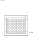
- FIG. 2 is a diagram illustrating an example of a pixel portion of the imaging device according to the first embodiment.
- An imaging device 1 includes a plurality of pixels P each including a photoelectric conversion unit and photoelectrically converts incident light to generate a signal.
- the photoelectric conversion unit is, for example, a photodiode and enables to photoelectrically converts light.
- the imaging device 1 has a region (pixel portion 100) in which the plurality of pixels P is two-dimensionally arranged in a matrix, as an imaging area.
- the imaging device 1 takes in incident light (image light) from an object, via an optical system (not illustrated) including an optical lens.
- the imaging device 1 images an image of the object formed by the optical lens.
- the imaging device 1 photoelectrically converts the received light and generates a pixel signal.
- the imaging device 1 is, for example, a Complementary Metal Oxide Semiconductor (CMOS) image sensor. It is possible to use the imaging device 1 for an electronic apparatus such as a digital still camera, a video camera, or a mobile phone.
- CMOS Complementary Metal Oxide Semiconductor
- an incident direction of the light from the object is referred to as a Z-axis direction
- a horizontal direction on paper perpendicular to the Z-axis direction is referred to as an X-axis direction
- a vertical direction on paper perpendicular to the Z-axis and the X-axis is referred to as a Y-axis direction.
- directions may be described with reference to the arrow directions in FIG. 2 .
- the imaging device 1 includes, for example, a vertical driving unit 111, a signal processor 112, a horizontal driving unit 113, an output unit 114, a controller 115, an input/output terminal 116, or the like, in a peripheral region of the pixel portion 100.
- a plurality of pixel driving lines Lread and a plurality of vertical signal lines VSL are provided.
- the plurality of pixel driving lines Lread is wired, for each pixel row including the plurality of pixels P arranged in a horizontal direction (row direction).
- the vertical signal line VSL is wired, for each pixel column including the plurality of pixels P arranged in a vertical direction (column direction).
- the pixel driving line Lread transmits a driving signal used to read a signal from the pixel P.
- the vertical signal line VSL is a signal line that enables to transfer the signal from the pixel P.
- the vertical signal line VSL transmits the signal outputted from the pixel P.
- the vertical driving unit 111 includes a shift register, an address decoder, or the like.
- the vertical driving unit 111 drives each pixel P of the pixel portion 100.
- the vertical driving unit 111 is a pixel driving unit and generates a signal used to drive the pixel P and outputs the signal to each pixel P of the pixel portion 100 via the pixel driving line Lread.
- the vertical driving unit 111 generates, for example, a signal used to control a transfer transistor, a signal used to control a reset transistor, or the like and supplies the signal to each pixel P through the pixel driving line Lread.
- the signal processor 112 executes signal processing on an inputted signal of the pixel.
- the signal processor 112 includes, for example, a load circuit unit, an Analog Digital (AD) conversion unit, a horizontal selection switch, or the like.
- AD Analog Digital
- a signal, outputted from each pixel P, selectively scanned by the vertical driving unit 111 is supplied to the signal processor 112 through the vertical signal line VSL.
- the signal processor 112 executes signal processing, for example, AD conversion, Correlated Double Sampling (CDS), or the like.
- the horizontal driving unit 113 includes a shift register, an address decoder, or the like.
- the horizontal driving unit 113 drives the horizontal selection switch of the signal processor 112.
- the horizontal driving unit 113 drives each horizontal selection switch of the signal processor 112 in sequence while scanning each horizontal selection switch.
- the signal processing is executed on the signal of each pixel P transmitted through each vertical signal line VSL by the signal processor 112, and the signal is outputted to a horizontal signal line 121 in sequence by selective scanning by the horizontal driving unit 113.
- the output unit 114 executes the signal processing on an inputted signal and outputs a signal.
- the output unit 114 executes the signal processing on a signal of a pixel sequentially inputted from the signal processor 112 via the horizontal signal line 121 and outputs the processed signal.
- the output unit 114 executes, for example, only buffering or executes black level adjustment, column variation correction, various types of digital signal processing, or the like.
- a circuit portion including the vertical driving unit 111, the signal processor 112, the horizontal driving unit 113, the horizontal signal line 121, and the output unit 114 may be formed on a semiconductor substrate 11 or may be disposed on an external control integrated circuit (IC). Furthermore, the circuit portion may be formed on another substrate coupled with a cable or the like.
- the controller 115 controls each unit of the imaging device 1.
- the controller 115 receives a clock given from outside of the semiconductor substrate 11, data that instructs an operation mode, or the like and also outputs data of internal information of the imaging device 1 or the like.
- the controller 115 includes a timing generator that generates various timing signals and drives and controls a peripheral circuit such as the vertical driving unit 111, the signal processor 112, or the horizontal driving unit 113, on the basis of the various timing signals generated by the timing generator.
- the input/output terminal 116 exchanges signals with outside.
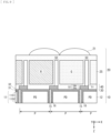
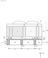
- FIG. 3 is a diagram illustrating an example of a cross-sectional configuration of the imaging device according to the first embodiment.
- FIG. 4 is a diagram illustrating an example of a plane configuration of the imaging device according to the first embodiment.
- the imaging device 1 includes a light receiving unit 10 and a light guide unit 20.
- the light receiving unit 10 includes the semiconductor substrate 11 having a first surface 11S1 and a second surface 11S2 opposed to each other.
- FIG. 3 illustrates an example of the cross-sectional configuration in a region with a long distance from the center of the pixel portion 100 (light receiving unit 10), that is, a high image height.
- the light guide unit 20 is provided on a side of the first surface 11S1 of the semiconductor substrate 11.
- a multi-layer wiring layer (not illustrated) is provided on a side of the second surface 11S2 of the semiconductor substrate 11.
- the imaging device 1 has a configuration in which the light receiving unit 10, the light guide unit 20, and the multi-layer wiring layer are stacked in the Z-axis direction. It is also said that the light guide unit 20 is provided on a side where light from an optical lens system enters and the multi-layer wiring layer is provided on a side opposite to the side where the light enters.
- the imaging device 1 is a so-called back-illuminated imaging device.
- the semiconductor substrate 11 includes, for example, a silicon substrate.
- a photoelectric conversion unit 12 is a photodiode (PD) and has pn junction in a predetermined region of the semiconductor substrate 11.
- the plurality of photoelectric conversion units 12 is embedded and formed in the semiconductor substrate 11. In the light receiving unit 10, the plurality of photoelectric conversion units 12 is provided along the first surface 11S1 and the second surface 11S2 of the semiconductor substrate 11.
- the multi-layer wiring layer provided on the side of the second surface 11S2 of the semiconductor substrate 11 has, for example, a configuration in which a plurality of wiring layers is stacked with an interlayer insulation layer therebetween.
- the wiring layer of the multi-layer wiring layer is formed using, for example, aluminum (Al), copper (Cu), tungsten (W), or the like.
- the interlayer insulation layer is formed using, for example, silicon oxide (SiOx), silicon nitride (SiNx), silicon oxynitride (SiOxNy), or the like.
- a circuit for example, transfer transistor, reset transistor, amplification transistor, or the like
- the vertical driving unit 111, the signal processor 112, the horizontal driving unit 113, the output unit 114, the controller 115, the input/output terminal 116, and the like described above are formed.
- the light guide unit 20 is stacked on the light receiving unit 10 in a thickness direction perpendicular to the first surface 11S1 of the semiconductor substrate 11.
- the light guide unit 20 includes a lens unit 21 and a color filter 25 and guides light entering from above toward a side of the light receiving unit 10.
- the lens unit 21 is an optical member called an on-chip lens and is provided above the color filter 25 for each pixel P, for example.
- the light from the object enters the lens unit 21 via the optical system of the imaging device 1.
- the photoelectric conversion unit 12 photoelectrically converts the light that enters via the lens unit 21 and the color filter 25.
- the color filter 25 selectively transmits light in a specific wavelength band of the incident light.
- the plurality of pixels P provided in the pixel portion 100 of the imaging device 1 includes a plurality of pixels Pr, pixels Pg, and pixels Pb, as illustrated in FIG. 4 .
- the plurality of pixels Pr, the plurality of pixels Pg, and the plurality of pixels Pb are repeatedly arranged.
- the pixel Pr is a pixel in which the color filter 25 that transmits red (R) light is provided.
- the red color filter 25 transmits light in a red wavelength band.
- the photoelectric conversion unit of the pixel Pr receives light of a red wavelength and performs photoelectric conversion.
- the pixel Pr is a pixel that receives light in the red wavelength band and generates a signal.
- the pixel Pg is a pixel in which the color filter 25 that transmits green (G) light is provided.
- the green color filter 25 transmits light in a green wavelength band.
- the photoelectric conversion unit of the pixel Pg receives light of a green wavelength and performs photoelectric conversion.
- the pixel Pg is a pixel that receives light in the green wavelength band and generates a signal.
- the pixel Pb is a pixel in which the color filter 25 that transmits blue (B) light is provided.
- the blue color filter 25 transmits light in a blue wavelength band.
- the photoelectric conversion unit of the pixel Pb receives light of a blue wavelength and performs photoelectric conversion.
- the pixel Pb is a pixel that receives light in the blue wavelength band and generates a signal.
- the pixel Pr, the pixel Pg, and the pixel Pb respectively generate a pixel signal of an R component, a pixel signal of a G component, and a pixel signal of a B component. Therefore, it is possible for the imaging device 1 to obtain the pixel signal of RGB.
- the separation unit 15 includes a trench 16 (groove portion).
- the trench 16 of the separation unit 15 is provided around the photoelectric conversion unit 12, in the semiconductor substrate 11.
- an oxide film is provided in the trench 16, for example.
- the trench 16 (groove) is formed between the adjacent photoelectric conversion units 12, and the oxide film is embedded in the trench 16.
- the metal compound layer 30 is provided on the photoelectric conversion unit 12 between the color filter 25 and the photoelectric conversion unit 12.
- the metal compound layer 30 includes a metal compound.
- the metal compound layer 30 is a layer including, for example, metal oxide or metal nitride.
- the metal compound layer 30 includes a fixed charge film 31 and an antireflection film 32.
- the fixed charge film 31 is a film having a fixed charge and is formed using a high dielectric.
- the fixed charge film 31 includes metal oxide, for example, hafnium oxide or the like and is provided on the photoelectric conversion unit 12.
- the fixed charge film 31 is formed between the photoelectric conversion unit 12 and the separation unit 15.
- the fixed charge film 31 is provided to cover the photoelectric conversion unit 12.
- the fixed charge film 31 is a film, for example, having a negative fixed charge and prevents generation of a dark current at an interface of the semiconductor substrate 11.
- the fixed charge film 31 is formed to include at least one of oxides, for example, hafnium (Hf), zirconium (Zr), aluminum (Al), titanium (Ti), tantalum (Ta), magnesium (Mg), yttrium (Y), a lanthanoid (La) element, and the like.
- the fixed charge film 31 may include praseodymium oxide, cerium oxide, neodymium oxide, promethium oxide, samarium oxide, europium oxide, gadolinium oxide, terbium oxide, dysprosium oxide, holmium oxide, thulium oxide, ytterbium oxide, lutetium oxide, yttrium oxide, or the like.
- the fixed charge film 31 may be configured using metal nitride or metal oxynitride such as an aluminum nitride film, a hafnium oxynitride film, or an aluminum oxynitride film. As the fixed charge film 31, a film having a positive fixed charge may be provided.
- the antireflection film 32 includes metal oxide, for example, tantalum oxide or the like and is provided on the fixed charge film 31.
- the antireflection film 32 is provided between the fixed charge film 31 and the oxide film layer 40 and reduces reflection.
- the antireflection film 32 may include other metal oxide films other than tantalum oxide or may include a metal nitride film or a metal oxynitride film.
- the fixed charge film 31 and the antireflection film 32 may be formed to cover side surfaces of the trench 16.
- the oxide film layer 40 is provided between the color filter 25 and the metal compound layer 30.
- the oxide film layer 40 is formed using silicon oxide (SiOx), for example.
- the oxide film layer 40 includes a silicon dioxide film, a silicon oxynitride film, or the like. Note that the oxide film layer 40 is also said as a planarization layer (planarization film).
- the imaging device 1 includes a structure 50 as illustrated in FIG. 3 .
- a portion of the structure 50 is provided between the adjacent color filters 25 and separates between the color filters 25.
- the structure 50 is also said as a separation wall (or separation unit) that has an air gap (cavity) provided between the adjacent color filters 25 and uses the air gap (cavity).
- the structure 50 is provided from between the adjacent color filters 25 to the metal compound layer 30 and is coupled to the separation unit 15.
- the structure 50 extends to between the oxide film layer 40 and the metal compound layer 30, as illustrated in FIG. 3 .
- a portion of the structure 50 is formed on the metal compound layer 30 and has contact with the metal compound layer 30.
- the structure 50 is provided around the color filter 25.
- the structure 50 includes a first section 51 provided between the adjacent color filters 25 and a second section 52 provided to the separation unit 15 along the metal compound layer 30.
- the first section 51 of the structure 50 is positioned between the adjacent color filters 25 and has a refractive index lower than a refractive index of a surrounding medium.
- the first section 51 of the structure 50 has the refractive index lower than a refractive index of the color filter 25.
- the first section 51 has air (air gap).
- the first section 51 of the structure 50 is a light guide unit and changes a traveling direction of incident light, in accordance with a refractive index difference between the first section 51 and the surrounding medium. It is also said that the imaging device 1 has a waveguiding structure that guides light using the first section 51 of the structure 50.
- the second section 52 of the structure 50 couples the first section 51 and the separation unit 15 and prevents leakage of light to the surrounding pixels P.
- the second section 52 of the structure 50 may include a metal film that absorbs light.
- the second section 52 may include tungsten (W).
- the light from the optical lens almost perpendicularly enters a middle portion of the pixel portion 100 of the imaging device 1.
- the light obliquely enters a peripheral portion positioned on an outer side of the middle portion, that is, a region apart from the middle of the pixel portion 100. Therefore, in the imaging device 1, positions of the lens unit 21 and the color filter 25 in each pixel P are set to differ depending on a distance from the center of the pixel portion 100 (light receiving unit 10), that is, the height.
- the lens unit 21 and the color filter 25 of the pixel P are arranged to be shifted to the middle side of the pixel portion 100 (light receiving unit 10), with respect to the photoelectric conversion unit 12 of the pixel P.
- the structure 50 includes the second section 52 having a size that differs depending on the distance from the center of the light receiving unit 10. For example, as a region is positioned farther from the middle of the pixel portion 100, a width (area) of the second section 52 of the structure 50 in that region is wider.
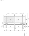
- the pixel P is configured, for example, as illustrated in FIG. 5 .
- respective center positions of the lens unit 21, the color filter 25, the photoelectric conversion unit 12 substantially match.
- the position of each of the lens unit 21 and the color filter 25 is adjusted in accordance with the height, and it is possible to appropriately perform pupil correction. It is possible to suppress decrease in an amount of the light for entering the photoelectric conversion unit 12 and to prevent reduction in sensitivity for the incident light.
- the hole is closed by the silicon dioxide film.
- the structure 50 having the air gap of the first section 51 is formed. According to the above manufacturing method, it is possible to manufacture the imaging device 1 illustrated in FIG. 3 or the like. Note that the above manufacturing method is merely an example, and another manufacturing method may be adopted.
- the imaging device (imaging device 1) includes the plurality of pixels (pixel P) including the photoelectric conversion unit (photoelectric conversion unit 12) that photoelectrically converts light, the color filter (color filter 25) provided for each pixel, the separation unit (15) provided between the adjacent photoelectric conversion units, the structure (structure 50) having the air gap provided between the adjacent color filters, and the metal compound layer (metal compound layer 30) provided on the photoelectric conversion unit, between the color filter and the photoelectric conversion unit.
- the structure is provided from between the adjacent color filters and to the metal compound layer and is coupled to the separation unit.
- a hole (opening) is formed in a portion of the silicon dioxide film on the a-Si film 53b, and etching is performed on the a-Si films 53b and 53a via the hole.
- the air gap that is the first section 51 of the structure 50 is formed.
- the structure 50 having the air gap is formed as illustrated in FIG. 8D . According to the above manufacturing method, it is possible to manufacture the imaging device 1 illustrated in FIG. 7 .
- the a-Si film 53 is formed, and a silicon dioxide film is formed, as a protection film, around the a-Si film 53.
- the color filter 25 is formed.
- FIG. 11 is a diagram illustrating an example of the cross-sectional configuration of the imaging device according to a third modification example.
- the second section 52 of the structure 50 may have the air gap and the plurality of metal films.
- the second section 52 of the structure 50 includes the first metal film 54a stacked on the metal compound layer 30, the second metal film 54b stacked on the first metal film 54a, and the air gap stacked on the second metal film 54b.
- a hole is formed in a portion of the silicon dioxide film on the a-Si film 53b, and etching is performed on the a-Si films 53b and 53a via the hole.
- the air gap of the structure 50 is formed.
- the structure 50 having the air gap is formed as illustrated in FIG. 12D . According to the above manufacturing method, it is possible to manufacture the imaging device 1 illustrated in FIG. 11 .
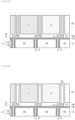
- FIGs. 14A to 14D are diagrams illustrating an example of a method for manufacturing the imaging device according to the fourth modification example.
- the metal compound layer 30 is formed on the semiconductor substrate 11, on which the elements such as the photoelectric conversion unit 12 are formed. Furthermore, the titanium nitride film that is the second section 52 of the structure 50 and the silicon dioxide film as the oxide film layer 40 are formed. A portion of the second section 52 of the structure 50 is embedded and formed in the separation unit 15. Then, by the CMP or the etch-back processing, the extra silicon dioxide film is removed.
- the structure 50 having the air gap is formed as illustrated in FIG. 14D . According to the above manufacturing method, it is possible to manufacture the imaging device 1 illustrated in FIG. 13 .
- the imaging device 1 by providing the first section 51 and the second section 52 having the air gap, it is possible to prevent leakage of light to surrounding pixels P and to prevent occurrence of color mixture. Furthermore, it is possible for the structure 50 having the air gap to effectively guide light to a photoelectric conversion unit 12, and it is possible to improve sensitivity for the incident light.
- the second section 52 of the structure 50 has the air gap and is formed to have contact with a metal compound layer 30. As compared with a case where a material with a low refractive index is formed in an oxide film layer, it is possible to reduce difficulty in manufacturing the imaging device 1.
- the pixel P is configured, for example, as illustrated in FIG. 16 .
- respective center positions of a lens unit 21, a color filter 25, and the photoelectric conversion unit 12 substantially match.
- a width w1 (refer to FIG. 16 ) of the second section 52 of the structure 50 in a middle portion of the pixel portion 100 is less than a width w2 (refer to FIG. 15 ) of the second section 52 of the structure 50 in a peripheral portion positioned on an outer side than the middle portion.
- the width w1 of the second section 52 of the structure 50 in the middle portion of the pixel portion 100 may be substantially equal to the width w2 of the second section 52 illustrated in FIG. 15 .
- the imaging device (imaging device 1) includes the plurality of pixels (pixel P) including the photoelectric conversion unit (photoelectric conversion unit 12) that photoelectrically converts light, the color filter (color filter 25) provided for each pixel, a separation unit (separation unit 15) provided between the adjacent photoelectric conversion units, the structure (structure 50) having the air gap (first section 51 and second section 52) provided between the adjacent color filters, and the metal compound layer (metal compound layer 30) provided on the photoelectric conversion unit between the color filter and the photoelectric conversion unit.
- the structure is provided from between the adjacent color filters to the metal compound layer and is coupled to the separation unit.
- the structure 50 is provided from between the adjacent color filters 25 to the metal compound layer 30 and is coupled to the separation unit 15. Therefore, it is possible to prevent the occurrence of the color mixture. It is possible to realize the imaging device 1 that enables to reduce the color mixture.
- the structure 50 includes the first section 51 provided between the adjacent color filters 25 and the second section 52 provided to the separation unit 15 along the metal compound layer 30.
- the first section 51 and the second section 52 have the air gap.
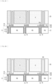
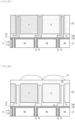
- FIGs. 18A to 18D are diagrams illustrating an example of a method for manufacturing the imaging device according to the second embodiment.
- the metal compound layer 30 is formed on a semiconductor substrate 11, on which elements such as the photoelectric conversion unit 12 are formed. Furthermore, as an oxide film layer 40, a silicon dioxide film is formed.
- an a-Si film 53 (amorphous silicon film) is formed by chemical vapor deposition (CVD), and a silicon dioxide film is formed, as a protection film, around the a-Si film 53.
- the color filter 25 is formed.
- holes are formed in a portion of the silicon dioxide film on the a-Si film 53, for example, at four corners of the pixel P, and etching is performed on the a-Si film 53 via the hole. As a result, the air gap of the first section 51 of the structure 50 is formed.
- the hole is closed by a silicon dioxide film.
- the structure 50 having the air gap of the first section 51 is formed.
- the lens unit 21 or the like it is possible to manufacture the imaging device 1 illustrated in FIG. 15 or the like. Note that the above manufacturing method is merely an example, and another manufacturing method may be adopted.
- FIG. 19 is a diagram illustrating an example of the cross-sectional configuration of the imaging device according to a fifth modification example of the present disclosure.
- a portion of the structure 50 may be provided in the separation unit 15.
- a portion of the second section 52, that is, the air gap of the structure 50 is formed in the separation unit 15.
- FIGs. 20A to 20D are diagrams illustrating an example of a method for manufacturing the imaging device according to the fifth modification example.
- the metal compound layer 30 is formed on the semiconductor substrate 11, on which the elements such as the photoelectric conversion unit 12 are formed. Furthermore, as the oxide film layer 40, a silicon dioxide film is formed.
- the a-Si film 53 is formed by the CVD, and a silicon dioxide film is formed, as a protection film, around the a-Si film 53. Then, as illustrated in FIG. 20C , the color filter 25 is formed.
- a hole is formed in a portion of the silicon dioxide film on the a-Si film 53, and etching is performed on the a-Si film 53 via the hole.
- the air gap is provided, and the first section 51 and the second section 52 of the structure 50 are formed.
- the structure 50 having the air gap is formed. According to the above manufacturing method, it is possible to manufacture the imaging device 1 illustrated in FIG. 19 .
- FIG. 21 is a diagram illustrating an example of the cross-sectional configuration of the imaging device according to a sixth modification example.
- the structure 50 of the imaging device 1 may include a protection film 45 provided between the color filter 25 and the air gap.
- the protection film 45 is provided between the first section 51 and the color filter 25.
- the protection film 45 includes an oxide film, a nitride film, or both.
- the protection film 45 may include a silicon dioxide film, a silicon nitride film, a silicon oxynitride film, a metal oxide film (for example, aluminum oxide or magnesium oxide), or the like.
- the imaging device 1 or the like is applicable to various types of electronic apparatuses having an imaging function, for example, a camera system such as a digital still camera or a video camera, a mobile phone having an imaging function, or the like.
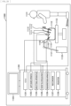
- FIG. 22 illustrates a schematic configuration of an electronic apparatus 1000.
- the electronic apparatus 1000 includes, for example, a lens group 1001, the imaging device 1, a Digital Signal Processor (DSP) circuit 1002, a frame memory 1003, a display 1004, a recording unit 1005, an operation unit 1006, and a power supply unit 1007, and these are coupled to each other via a bus line 1008.
- DSP Digital Signal Processor
- the lens group 1001 takes in incident light (image light) from an object and forms an image on an imaging surface of the imaging device 1.
- the imaging device 1 converts a light amount of the incident light for forming the image on the imaging surface with the lens group 1001 into an electric signal in pixel units and supplies the electric signal to the DSP circuit 1002 as a pixel signal.
- the DSP circuit 1002 is a signal processing circuit that processes the signal supplied from the imaging device 1.
- the DSP circuit 1002 outputs image data obtained by processing the signal from the imaging device 1.
- the frame memory 1003 temporality holds the image data processed by the DSP circuit 1002 in frame units.
- the display 1004 includes a panel-type display device, for example, a liquid crystal panel, an organic Electro Luminescence (EL) panel, or the like and records image data of a moving image or a still image imaged by the imaging device 1 in a recording medium such as a semiconductor memory or a hard disk.
- a panel-type display device for example, a liquid crystal panel, an organic Electro Luminescence (EL) panel, or the like and records image data of a moving image or a still image imaged by the imaging device 1 in a recording medium such as a semiconductor memory or a hard disk.
- the operation unit 1006 outputs operation signals regarding various functions of the electronic apparatus 1000, in accordance with an operation by a user.
- the power supply unit 1007 appropriately supplies various power supplies to be operation power supplies of the DSP circuit 1002, the frame memory 1003, the display 1004, the recording unit 1005, and the operation unit 1006, to these supply targets.
- a technique of the present disclosure (the present technique) is applicable to various products.
- the technique of the present disclosure may be implemented as a device to be mounted on any type of movable bodies such as automobiles, electric automobiles, hybrid electric automobiles, motorcycles, bicycles, personal mobilities, airplanes, drones, vessels, or robots.
- FIG. 23 is a block diagram depicting an example of schematic configuration of a vehicle control system as an example of a mobile body control system to which the technology according to an embodiment of the present disclosure can be applied.
- the vehicle control system 12000 includes a plurality of electronic control units connected to each other via a communication network 12001.
- the vehicle control system 12000 includes a driving system control unit 12010, a body system control unit 12020, an outside-vehicle information detecting unit 12030, an in-vehicle information detecting unit 12040, and an integrated control unit 12050.
- a microcomputer 12051, a sound/image output section 12052, and a vehicle-mounted network interface (I/F) 12053 are illustrated as a functional configuration of the integrated control unit 12050.
- the driving system control unit 12010 controls the operation of devices related to the driving system of the vehicle in accordance with various kinds of programs.
- the driving system control unit 12010 functions as a control device for a driving force generating device for generating the driving force of the vehicle, such as an internal combustion engine, a driving motor, or the like, a driving force transmitting mechanism for transmitting the driving force to wheels, a steering mechanism for adjusting the steering angle of the vehicle, a braking device for generating the braking force of the vehicle, and the like.
- the body system control unit 12020 controls the operation of various kinds of devices provided to a vehicle body in accordance with various kinds of programs.
- the body system control unit 12020 functions as a control device for a keyless entry system, a smart key system, a power window device, or various kinds of lamps such as a headlamp, a backup lamp, a brake lamp, a turn signal, a fog lamp, or the like.
- radio waves transmitted from a mobile device as an alternative to a key or signals of various kinds of switches can be input to the body system control unit 12020.
- the body system control unit 12020 receives these input radio waves or signals, and controls a door lock device, the power window device, the lamps, or the like of the vehicle.
- the outside-vehicle information detecting unit 12030 detects information about the outside of the vehicle including the vehicle control system 12000.
- the outside-vehicle information detecting unit 12030 is connected with an imaging section 12031.
- the outside-vehicle information detecting unit 12030 makes the imaging section 12031 image an image of the outside of the vehicle, and receives the imaged image.
- the outside-vehicle information detecting unit 12030 may perform processing of detecting an object such as a human, a vehicle, an obstacle, a sign, a character on a road surface, or the like, or processing of detecting a distance thereto.
- the imaging section 12031 is an optical sensor that receives light, and which outputs an electric signal corresponding to a received light amount of the light.
- the imaging section 12031 can output the electric signal as an image, or can output the electric signal as information about a measured distance.
- the light received by the imaging section 12031 may be visible light, or may be invisible light such as infrared rays or the like.
- the in-vehicle information detecting unit 12040 detects information about the inside of the vehicle.
- the in-vehicle information detecting unit 12040 is, for example, connected with a driver state detecting section 12041 that detects the state of a driver.
- the driver state detecting section 12041 for example, includes a camera that images the driver.
- the in-vehicle information detecting unit 12040 may calculate a degree of fatigue of the driver or a degree of concentration of the driver, or may determine whether the driver is dozing.
- the microcomputer 12051 can calculate a control target value for the driving force generating device, the steering mechanism, or the braking device on the basis of the information about the inside or outside of the vehicle which information is obtained by the outside-vehicle information detecting unit 12030 or the in-vehicle information detecting unit 12040, and output a control command to the driving system control unit 12010.
- the microcomputer 12051 can perform cooperative control intended to implement functions of an advanced driver assistance system (ADAS) which functions include collision avoidance or shock mitigation for the vehicle, following driving based on a following distance, vehicle speed maintaining driving, a warning of collision of the vehicle, a warning of deviation of the vehicle from a lane, or the like.
- ADAS advanced driver assistance system
- the microcomputer 12051 can perform cooperative control intended for automated driving, which makes the vehicle to travel automatedly without depending on the operation of the driver, or the like, by controlling the driving force generating device, the steering mechanism, the braking device, or the like on the basis of the information about the outside or inside of the vehicle which information is obtained by the outside-vehicle information detecting unit 12030 or the in-vehicle information detecting unit 12040.
- the microcomputer 12051 can output a control command to the body system control unit 12020 on the basis of the information about the outside of the vehicle which information is obtained by the outside-vehicle information detecting unit 12030.
- the microcomputer 12051 can perform cooperative control intended to prevent a glare by controlling the headlamp so as to change from a high beam to a low beam, for example, in accordance with the position of a preceding vehicle or an oncoming vehicle detected by the outside-vehicle information detecting unit 12030.
- the sound/image output section 12052 transmits an output signal of at least one of a sound and an image to an output device capable of visually or auditorily notifying information to an occupant of the vehicle or the outside of the vehicle.
- an audio speaker 12061, a display section 12062, and an instrument panel 12063 are illustrated as the output device.
- the display section 12062 may, for example, include at least one of an on-board display and a head-up display.
- FIG. 24 is a diagram depicting an example of the installation position of the imaging section 12031.
- the imaging section 12031 includes imaging sections 12101, 12102, 12103, 12104, and 12105.
- the imaging sections 12101, 12102, 12103, 12104, and 12105 are, for example, disposed at positions on a front nose, sideview mirrors, a rear bumper, and a back door of the vehicle 12100 as well as a position on an upper portion of a windshield within the interior of the vehicle.
- the imaging section 12101 provided to the front nose and the imaging section 12105 provided to the upper portion of the windshield within the interior of the vehicle obtain mainly an image of the front of the vehicle 12100.
- the imaging sections 12102 and 12103 provided to the sideview mirrors obtain mainly an image of the sides of the vehicle 12100.
- the imaging section 12104 provided to the rear bumper or the back door obtains mainly an image of the rear of the vehicle 12100.
- the imaging section 12105 provided to the upper portion of the windshield within the interior of the vehicle is used mainly to detect a preceding vehicle, a pedestrian, an obstacle, a signal, a traffic sign, a lane, or the like.
- FIG. 24 depicts an example of photographing ranges of the imaging sections 12101 to 12104.
- An imaging range 12111 represents the imaging range of the imaging section 12101 provided to the front nose.
- Imaging ranges 12112 and 12113 respectively represent the imaging ranges of the imaging sections 12102 and 12103 provided to the sideview mirrors.
- An imaging range 12114 represents the imaging range of the imaging section 12104 provided to the rear bumper or the back door.
- a bird's-eye image of the vehicle 12100 as viewed from above is obtained by superimposing image data imaged by the imaging sections 12101 to 12104, for example.
- At least one of the imaging sections 12101 to 12104 may have a function of obtaining distance information.
- at least one of the imaging sections 12101 to 12104 may be a stereo camera constituted of a plurality of imaging elements, or may be an imaging element having pixels for phase difference detection.
- the microcomputer 12051 can determine a distance to each three-dimensional object within the imaging ranges 12111 to 12114 and a temporal change in the distance (relative speed with respect to the vehicle 12100) on the basis of the distance information obtained from the imaging sections 12101 to 12104, and thereby extract, as a preceding vehicle, a nearest three-dimensional object in particular that is present on a traveling path of the vehicle 12100 and which travels in substantially the same direction as the vehicle 12100 at a predetermined speed (for example, equal to or more than 0 km/hour). Further, the microcomputer 12051 can set a following distance to be maintained in front of a preceding vehicle in advance, and perform automatic brake control (including following stop control), automatic acceleration control (including following start control), or the like. It is thus possible to perform cooperative control intended for automated driving that makes the vehicle travel automatedly without depending on the operation of the driver or the like.
- automatic brake control including following stop control
- automatic acceleration control including following start control
- the microcomputer 12051 can classify three-dimensional object data on three-dimensional objects into three-dimensional object data of a two-wheeled vehicle, a standard-sized vehicle, a large-sized vehicle, a pedestrian, a utility pole, and other three-dimensional objects on the basis of the distance information obtained from the imaging sections 12101 to 12104, extract the classified three-dimensional object data, and use the extracted three-dimensional object data for automatic avoidance of an obstacle.
- the microcomputer 12051 identifies obstacles around the vehicle 12100 as obstacles that the driver of the vehicle 12100 can recognize visually and obstacles that are difficult for the driver of the vehicle 12100 to recognize visually. Then, the microcomputer 12051 determines a collision risk indicating a risk of collision with each obstacle.
- the microcomputer 12051 In a situation in which the collision risk is equal to or higher than a set value and there is thus a possibility of collision, the microcomputer 12051 outputs a warning to the driver via the audio speaker 12061 or the display section 12062, and performs forced deceleration or avoidance steering via the driving system control unit 12010. The microcomputer 12051 can thereby assist in driving to avoid collision.
- At least one of the imaging sections 12101 to 12104 may be an infrared camera that detects infrared rays.
- the microcomputer 12051 can, for example, recognize a pedestrian by determining whether or not there is a pedestrian in imaged images of the imaging sections 12101 to 12104. Such recognition of a pedestrian is, for example, performed by a procedure of extracting characteristic points in the imaged images of the imaging sections 12101 to 12104 as infrared cameras and a procedure of determining whether or not it is the pedestrian by performing pattern matching processing on a series of characteristic points representing the contour of the object.
- the sound/image output section 12052 controls the display section 12062 so that a square contour line for emphasis is displayed so as to be superimposed on the recognized pedestrian.
- the sound/image output section 12052 may also control the display section 12062 so that an icon or the like representing the pedestrian is displayed at a desired position.
- the technique of the present disclosure may be applied to, for example, the imaging section 12031, among the components described above.
- the imaging device 1 or the like is applicable to the imaging section 12031.
- the technique of the present disclosure is applicable to various products.
- the technique of the present disclosure may be applied to an endoscopic surgery system.
- the display apparatus 11202 displays thereon an image based on an image signal, for which the image processes have been performed by the CCU 11201, under the control of the CCU 11201.
- the camera head 11102 includes a lens unit 11401, an image pickup unit 11402, a driving unit 11403, a communication unit 11404 and a camera head controlling unit 11405.
- the CCU 11201 includes a communication unit 11411, an image processing unit 11412 and a control unit 11413.
- the camera head 11102 and the CCU 11201 are connected for communication to each other by a transmission cable 11400.
- the lens unit 11401 is an optical system, provided at a connecting location to the lens barrel 11101. Observation light taken in from a distal end of the lens barrel 11101 is guided to the camera head 11102 and introduced into the lens unit 11401.
- the lens unit 11401 includes a combination of a plurality of lenses including a zoom lens and a focusing lens.
- the number of image pickup elements which is included by the image pickup unit 11402 may be one (single-plate type) or a plural number (multi-plate type). Where the image pickup unit 11402 is configured as that of the multi-plate type, for example, image signals corresponding to respective R, G and B are generated by the image pickup elements, and the image signals may be synthesized to obtain a color image.
- the image pickup unit 11402 may also be configured so as to have a pair of image pickup elements for acquiring respective image signals for the right eye and the left eye ready for three dimensional (3D) display. If 3D display is performed, then the depth of a living body tissue in a surgical region can be comprehended more accurately by the surgeon 11131. It is to be noted that, where the image pickup unit 11402 is configured as that of stereoscopic type, a plurality of systems of lens units 11401 are provided corresponding to the individual image pickup elements.
- the image pickup unit 11402 may not necessarily be provided on the camera head 11102.
- the image pickup unit 11402 may be provided immediately behind the objective lens in the inside of the lens barrel 11101.
- the driving unit 11403 includes an actuator and moves the zoom lens and the focusing lens of the lens unit 11401 by a predetermined distance along an optical axis under the control of the camera head controlling unit 11405. Consequently, the magnification and the focal point of a picked up image by the image pickup unit 11402 can be adjusted suitably.
- the communication unit 11404 includes a communication apparatus for transmitting and receiving various kinds of information to and from the CCU 11201.
- the communication unit 11404 transmits an image signal acquired from the image pickup unit 11402 as RAW data to the CCU 11201 through the transmission cable 11400.
- the communication unit 11404 receives a control signal for controlling driving of the camera head 11102 from the CCU 11201 and supplies the control signal to the camera head controlling unit 11405.
- the control signal includes information relating to image pickup conditions such as, for example, information that a frame rate of a picked up image is designated, information that an exposure value upon image picking up is designated and/or information that a magnification and a focal point of a picked up image are designated.
- the image pickup conditions such as the frame rate, exposure value, magnification or focal point may be designated by the user or may be set automatically by the control unit 11413 of the CCU 11201 on the basis of an acquired image signal.
- an auto exposure (AE) function, an auto focus (AF) function and an auto white balance (AWB) function are incorporated in the endoscope 11100.
- the camera head controlling unit 11405 controls driving of the camera head 11102 on the basis of a control signal from the CCU 11201 received through the communication unit 11404.
- the communication unit 11411 transmits a control signal for controlling driving of the camera head 11102 to the camera head 11102.
- the image signal and the control signal can be transmitted by electrical communication, optical communication or the like.
- the image processing unit 11412 performs various image processes for an image signal in the form of RAW data transmitted thereto from the camera head 11102.
- the control unit 11413 performs various kinds of control relating to image picking up of a surgical region or the like by the endoscope 11100 and display of a picked up image obtained by image picking up of the surgical region or the like. For example, the control unit 11413 creates a control signal for controlling driving of the camera head 11102.
- control unit 11413 controls, on the basis of an image signal for which image processes have been performed by the image processing unit 11412, the display apparatus 11202 to display a picked up image in which the surgical region or the like is imaged.
- control unit 11413 may recognize various objects in the picked up image using various image recognition technologies.
- the control unit 11413 can recognize a surgical tool such as forceps, a particular living body region, bleeding, mist when the energy device 11112 is used and so forth by detecting the shape, color and so forth of edges of objects included in a picked up image.
- the control unit 11413 may cause, when it controls the display apparatus 11202 to display a picked up image, various kinds of surgery supporting information to be displayed in an overlapping manner with an image of the surgical region using a result of the recognition. Where surgery supporting information is displayed in an overlapping manner and presented to the surgeon 11131, the burden on the surgeon 11131 can be reduced and the surgeon 11131 can proceed with the surgery with certainty.
- the transmission cable 11400 which connects the camera head 11102 and the CCU 11201 to each other is an electric signal cable ready for communication of an electric signal, an optical fiber ready for optical communication or a composite cable ready for both of electrical and optical communications.
- communication is performed by wired communication using the transmission cable 11400
- the communication between the camera head 11102 and the CCU 11201 may be performed by wireless communication.
- the technique of the present disclosure may be preferably applied to, for example, the image pickup unit 11402 provided in the camera head 11102 of the endoscope 11100, among the components described above.
- the technique of the present disclosure it is possible to increase sensitivity of the image pickup unit 11402 and to provide the high-definition endoscope 11100.
- the imaging device includes the plurality of pixels including the photoelectric conversion unit that photoelectrically converts light, the color filter provided for each pixel, the separation unit provided between the adjacent photoelectric conversion units, the structure having the air gap provided between the adjacent color filters, and the metal compound layer provided on the photoelectric conversion unit between the color filter and the photoelectric conversion unit.
- the structure is provided from between the adjacent color filters to the metal compound layer and is coupled to the separation unit. Therefore, it is possible to prevent the occurrence of the color mixture.
Landscapes
- Solid State Image Pick-Up Elements (AREA)
Applications Claiming Priority (2)
| Application Number | Priority Date | Filing Date | Title |
|---|---|---|---|
| JP2022123953 | 2022-08-03 | ||
| PCT/JP2023/027249 WO2024029408A1 (ja) | 2022-08-03 | 2023-07-25 | 撮像装置 |
Publications (2)
| Publication Number | Publication Date |
|---|---|
| EP4567892A1 true EP4567892A1 (de) | 2025-06-11 |
| EP4567892A4 EP4567892A4 (de) | 2025-11-19 |
Family
ID=89849011
Family Applications (1)
| Application Number | Title | Priority Date | Filing Date |
|---|---|---|---|
| EP23849963.6A Pending EP4567892A4 (de) | 2022-08-03 | 2023-07-25 | Abbildungsvorrichtung |
Country Status (5)
| Country | Link |
|---|---|
| EP (1) | EP4567892A4 (de) |
| JP (1) | JPWO2024029408A1 (de) |
| KR (1) | KR20250044877A (de) |
| CN (1) | CN119404615A (de) |
| WO (1) | WO2024029408A1 (de) |
Families Citing this family (1)
| Publication number | Priority date | Publication date | Assignee | Title |
|---|---|---|---|---|
| WO2026071148A1 (ja) * | 2024-09-30 | 2026-04-02 | ソニーセミコンダクタソリューションズ株式会社 | 光検出装置、撮像装置、および電子機器 |
Family Cites Families (11)
| Publication number | Priority date | Publication date | Assignee | Title |
|---|---|---|---|---|
| JP2014022448A (ja) * | 2012-07-13 | 2014-02-03 | Toshiba Corp | 固体撮像装置 |
| KR102506837B1 (ko) | 2017-11-20 | 2023-03-06 | 삼성전자주식회사 | 이미지 센서 및 그 제조 방법 |
| US20210408090A1 (en) * | 2018-11-16 | 2021-12-30 | Sony Semiconductor Solutions Corporation | Imaging device |
| KR102658571B1 (ko) * | 2019-06-11 | 2024-04-19 | 에스케이하이닉스 주식회사 | 이미지 센싱 장치 및 그 제조 방법 |
| KR102691365B1 (ko) * | 2019-09-02 | 2024-08-05 | 에스케이하이닉스 주식회사 | 이미지 센싱 장치 |
| KR102721163B1 (ko) * | 2019-09-24 | 2024-10-24 | 에스케이하이닉스 주식회사 | 이미지 센싱 장치 |
| US20230131416A1 (en) * | 2020-03-31 | 2023-04-27 | Sony Semiconductor Solutions Corporation | Imaging element and imaging device |
| KR20220040848A (ko) * | 2020-09-24 | 2022-03-31 | 삼성전자주식회사 | 이미지 센서 |
| JP2022083419A (ja) * | 2020-11-24 | 2022-06-03 | 三星電子株式会社 | イメージセンサ |
| KR102883962B1 (ko) * | 2020-12-21 | 2025-11-10 | 에스케이하이닉스 주식회사 | 이미지 센싱 장치 |
| JP2022123953A (ja) | 2021-02-15 | 2022-08-25 | 新明工業株式会社 | 図書館の所蔵本返却補助台車および追従台車 |
-
2023
- 2023-07-25 WO PCT/JP2023/027249 patent/WO2024029408A1/ja not_active Ceased
- 2023-07-25 KR KR1020257004903A patent/KR20250044877A/ko active Pending
- 2023-07-25 CN CN202380047049.XA patent/CN119404615A/zh active Pending
- 2023-07-25 EP EP23849963.6A patent/EP4567892A4/de active Pending
- 2023-07-25 JP JP2024538956A patent/JPWO2024029408A1/ja active Pending
Also Published As
| Publication number | Publication date |
|---|---|
| JPWO2024029408A1 (de) | 2024-02-08 |
| CN119404615A (zh) | 2025-02-07 |
| WO2024029408A1 (ja) | 2024-02-08 |
| EP4567892A4 (de) | 2025-11-19 |
| KR20250044877A (ko) | 2025-04-01 |
Similar Documents
| Publication | Publication Date | Title |
|---|---|---|
| EP4415047A1 (de) | Abbildungsvorrichtung | |
| US12316987B2 (en) | Solid-state imaging device | |
| US20260075974A1 (en) | Imaging device | |
| US12439721B2 (en) | Solid-state imaging device | |
| US20250198843A1 (en) | Light detecting device | |
| EP4160685A1 (de) | Bildgebungselement und bildgebungsvorrichtung | |
| US20240030252A1 (en) | Solid-state imaging device and electronic apparatus | |
| WO2019207978A1 (ja) | 撮像素子および撮像素子の製造方法 | |
| US20250089385A1 (en) | Imaging device | |
| US20240347557A1 (en) | Imaging device | |
| EP4567892A1 (de) | Abbildungsvorrichtung | |
| WO2024095832A1 (en) | Photodetector, electronic apparatus, and optical element | |
| US20250185397A1 (en) | Imaging device | |
| US20250072146A1 (en) | Light detecting device | |
| US12514014B2 (en) | Semiconductor chip, manufacturing method for semiconductor chip, and electronic device | |
| WO2023079835A1 (ja) | 光電変換装置 | |
| US20250160016A1 (en) | Imaging device and electronic apparatus | |
| US20260129990A1 (en) | Photodetector and electronic apparatus | |
| US20260075976A1 (en) | Photodetection device and electronic apparatus | |
| US20250022897A1 (en) | Light detection device and optical filter | |
| WO2023067935A1 (ja) | 撮像装置 | |
| WO2022130987A1 (ja) | 固体撮像装置およびその製造方法 |
Legal Events
| Date | Code | Title | Description |
|---|---|---|---|
| STAA | Information on the status of an ep patent application or granted ep patent |
Free format text: STATUS: THE INTERNATIONAL PUBLICATION HAS BEEN MADE |
|
| PUAI | Public reference made under article 153(3) epc to a published international application that has entered the european phase |
Free format text: ORIGINAL CODE: 0009012 |
|
| STAA | Information on the status of an ep patent application or granted ep patent |
Free format text: STATUS: REQUEST FOR EXAMINATION WAS MADE |
|
| 17P | Request for examination filed |
Effective date: 20250223 |
|
| AK | Designated contracting states |
Kind code of ref document: A1 Designated state(s): AL AT BE BG CH CY CZ DE DK EE ES FI FR GB GR HR HU IE IS IT LI LT LU LV MC ME MK MT NL NO PL PT RO RS SE SI SK SM TR |
|
| REG | Reference to a national code |
Ref country code: DE Ref legal event code: R079 Free format text: PREVIOUS MAIN CLASS: H01L0027146000 Ipc: H10F0039000000 |
|
| DAV | Request for validation of the european patent (deleted) | ||
| DAX | Request for extension of the european patent (deleted) | ||
| A4 | Supplementary search report drawn up and despatched |
Effective date: 20251021 |
|
| RIC1 | Information provided on ipc code assigned before grant |
Ipc: H10F 39/00 20250101AFI20251015BHEP Ipc: H10F 39/12 20250101ALI20251015BHEP |